EP1439986B1 - Fahrzeugbelüftungsvorrichtung, insbesondere für ein kraftfahrzeug - Google Patents
Fahrzeugbelüftungsvorrichtung, insbesondere für ein kraftfahrzeug Download PDFInfo
- Publication number
- EP1439986B1 EP1439986B1 EP02774520A EP02774520A EP1439986B1 EP 1439986 B1 EP1439986 B1 EP 1439986B1 EP 02774520 A EP02774520 A EP 02774520A EP 02774520 A EP02774520 A EP 02774520A EP 1439986 B1 EP1439986 B1 EP 1439986B1
- Authority
- EP
- European Patent Office
- Prior art keywords
- instrument panel
- region
- airbag
- panel wall
- air
- Prior art date
- Legal status (The legal status is an assumption and is not a legal conclusion. Google has not performed a legal analysis and makes no representation as to the accuracy of the status listed.)
- Expired - Lifetime
Links
Images


Classifications
-
- B—PERFORMING OPERATIONS; TRANSPORTING
- B60—VEHICLES IN GENERAL
- B60R—VEHICLES, VEHICLE FITTINGS, OR VEHICLE PARTS, NOT OTHERWISE PROVIDED FOR
- B60R21/00—Arrangements or fittings on vehicles for protecting or preventing injuries to occupants or pedestrians in case of accidents or other traffic risks
- B60R21/02—Occupant safety arrangements or fittings, e.g. crash pads
- B60R21/16—Inflatable occupant restraints or confinements designed to inflate upon impact or impending impact, e.g. air bags
- B60R21/20—Arrangements for storing inflatable members in their non-use or deflated condition; Arrangement or mounting of air bag modules or components
- B60R21/205—Arrangements for storing inflatable members in their non-use or deflated condition; Arrangement or mounting of air bag modules or components in dashboards
-
- B—PERFORMING OPERATIONS; TRANSPORTING
- B60—VEHICLES IN GENERAL
- B60H—ARRANGEMENTS OF HEATING, COOLING, VENTILATING OR OTHER AIR-TREATING DEVICES SPECIALLY ADAPTED FOR PASSENGER OR GOODS SPACES OF VEHICLES
- B60H1/00—Heating, cooling or ventilating devices
- B60H1/00507—Details, e.g. mounting arrangements, desaeration devices
- B60H1/00514—Details of air conditioning housings
- B60H1/0055—Details of air conditioning housings the housing or parts thereof being integrated in other devices, e.g. dashboard
-
- B—PERFORMING OPERATIONS; TRANSPORTING
- B60—VEHICLES IN GENERAL
- B60R—VEHICLES, VEHICLE FITTINGS, OR VEHICLE PARTS, NOT OTHERWISE PROVIDED FOR
- B60R21/00—Arrangements or fittings on vehicles for protecting or preventing injuries to occupants or pedestrians in case of accidents or other traffic risks
- B60R21/02—Occupant safety arrangements or fittings, e.g. crash pads
- B60R21/04—Padded linings for the vehicle interior ; Energy absorbing structures associated with padded or non-padded linings
- B60R21/045—Padded linings for the vehicle interior ; Energy absorbing structures associated with padded or non-padded linings associated with the instrument panel or dashboard
-
- B—PERFORMING OPERATIONS; TRANSPORTING
- B60—VEHICLES IN GENERAL
- B60R—VEHICLES, VEHICLE FITTINGS, OR VEHICLE PARTS, NOT OTHERWISE PROVIDED FOR
- B60R21/00—Arrangements or fittings on vehicles for protecting or preventing injuries to occupants or pedestrians in case of accidents or other traffic risks
- B60R21/02—Occupant safety arrangements or fittings, e.g. crash pads
- B60R21/16—Inflatable occupant restraints or confinements designed to inflate upon impact or impending impact, e.g. air bags
- B60R21/20—Arrangements for storing inflatable members in their non-use or deflated condition; Arrangement or mounting of air bag modules or components
- B60R21/217—Inflation fluid source retainers, e.g. reaction canisters; Connection of bags, covers, diffusers or inflation fluid sources therewith or together
- B60R21/2171—Inflation fluid source retainers, e.g. reaction canisters; Connection of bags, covers, diffusers or inflation fluid sources therewith or together specially adapted for elongated cylindrical or bottle-like inflators with a symmetry axis perpendicular to the main direction of bag deployment, e.g. extruded reaction canisters
Definitions
- the invention relates to a ventilation device for a vehicle, in particular for a Motor vehicle, according to the preamble of claim 1.
- a known ventilation device for a motor vehicle is well known and schematically shown in Figures 9 to 11, wherein the figure 9 is a cross section through an instrument panel 100 of the ventilation device 101, which in the passenger area 102 a front instrument panel wall portion associated with a windshield 103 104 and seen in cross section through the instrument panel 100 of the Windshield 103 away in the direction of the vehicle interior 105 at the front Instrument panel wall portion 104 subsequent rear Instrument panel wall area 106 as a potential head impact panel wall area having.
- the ventilation device 101 further has one with one here illustrated air supply device coupled Wegströmer air supply channel 107 for air supply to arranged in instrument panel wall area LORDsen which are also not shown here, wherein the Wegströmer air supply channel is covered by the instrument panel 100.
- FIG. 9 in the vehicle longitudinal axis direction seen before the Wegströmer air supply channel 107 with a not here illustrated defroster air supply device coupled defroster air duct 108th provided below the front panel wall portion 104 and extends substantially along the lower windshield rim area, wherein in the front instrument panel wall portion 104 not shown here defroster are present for supplying the air from the defroster air duct to the windshield 103rd
- the figure 10 can be seen that the Wegströmer air supply channel 107 and the defroster air duct 108 integrally connected to each other and fixed over flat weld connection surfaces 109 on a dashboard underside are.
- Fig. 11 is a plan view of the Wegströmer air supply channel 107 and the defroster air channel 108.
- one in FIG. 11 is merely dashed line drawn airbag module 111, consisting of a total associated with Gas generator in an airbag housing received airbag, below the potential Head impact panel wall portion 106 arranged to the airbag immediately and fast in the passenger area before being in a normal sitting position Be able to inflate passenger. Due to this arrangement of the airbag in the rear Dashboard area 106, the airbag here thus immediately after its activation immediately in the inflation area with high inflation pressure of e.g. about 30 bar in front of the passenger inflated. Such a structure is particularly problematic in connection with itself not in a normal out-of-position vehicle occupant, e.g.
- the passenger air supply duct 107 is here U-shaped around the airbag module 111 arranged around it to lead to the peripheral turnedausströmem. This is cumbersome and may be related to unwanted flow losses lead the Ausström antique. On the other hand, this also requires a high cost of materials in the production of passenger air supply ducts.
- An airbag module that at least an airbag and at least one gas generator, which in an airbag housing are included, is covered in the assembled state of the instrument panel.
- the airbag module is in the passenger area in Vehicle longitudinal axis seen in a space in front of the passenger air supply duct arranged and thus essentially outside the potential Head impact instrument panel wall area, the front fascia wall area assigned, arranged. With this structure of the instrument panel is thus achieved that the airbag module outside of the potential head impact panel wall area is arranged.
- the front fascia wall area with a variety of a particular one Form perforation pattern forming air passage openings to in Vehicle interior to obtain a diffuse ventilation in this area.
- the Air outlet speed in the area of the air passage openings in contrast to conventional discharge nozzles considerably reduced, so that it is none of the Vehicle occupants as uncomfortable, drafty ventilation due to high Air outflow speeds comes.
- the object of the invention is a ventilation device for a vehicle, in particular for a motor vehicle to create, which is simple and easy to operate an optimal air supply for the vehicle interior is possible.
- the windshield facing front Instrument panel wall area at least partially air passage openings for diffuse ventilation of the vehicle interior. From the personal air outlet air supply duct starting at least one stitch channel in the area below the Passed air passage openings.
- the claimedausströmer air supply duct advantageous for air supply to the in Instrument panel wall area arranged Jardinausströmerdüsen as well as in a Dual function for easy and reliable air supply by means of at least a branch channel, which emanates from the passenger outlet air supply channel, to those in the front Instrument panel wall region at least partially arranged Air vents used for a diffuse ventilation of the vehicle interior become.
- a simple construction of the ventilation device is created, since no separate ducting with optional extra control panel for air supply to the Air passage openings is necessary.
- the relatively inexpensive can be produced.
- impact-resistant components such. in particular Airbag module comprising at least one airbag and at least one gas generator
- the rear instrument panel wall area as a potential head impact panel wall area at least partially from an energy-absorbing Material is manufactured, in a head impact on this area already relatively much Impact energy are absorbed, resulting in a significant reduction of Danger of injury to the vehicle occupants leads.
- the potential head impact panel wall area essentially from a preferably coated with a slush skin carrier layer an energy absorption foam material.
- a structure is at a high effectiveness also relatively cheap feasible.
- Another advantage of this new air duct concept is that it means the shortest possible Connecting channels of the air duct to the personal air vents, which regularly in Rear panel, the vehicle occupants facing instrument panel area are arranged, result. This is particularly the case when the Moausströmer air supply duct in a vehicle dash axis direction middle instrument panel area is coupled to the air supply device and from there in about straight in the vehicle transverse axis direction to at least one edge claimedausströmerdüse is guided. This can also reduce any flow losses.
- the rectilinear design of mecanicströmer air supply channel in Contrary to the U-shaped structure of the generic prior art also Material can be saved, which is particularly in connection with a series production proves to be particularly advantageous in terms of material costs.
- the passenger air supply duct may be integrally formed with the underside of the instrument panel or may be fixed by a screw and / or clip and / or welded connection substantially airtight on the underside of the instrument panel.
- the present invention of the proposedausströmer air supply channel outgoing at least one branch channel so in the Be guided area of the air passage openings in the front instrument panel wall area, that this seen from above in the free space in front of the proposedausströmer air supply channel arranged airbag module is not covered. This is not a hindrance to the inflating airbags through the or the puncture channels possible. This contributes to the Ensuring functional safety of the arrangement.
- a supporting body of the front instrument panel wall portion be integrated at least one exhaust nozzle, which then advantageously with the at least one branch channel is directly connected. This can thus be total easily realize a very good opportunity for diffuse ventilation.
- the base body is covered here from above by means of a cover which is perforated throughout with a perforation pattern such that over the Perforations as air passage openings in the region of the at least one exhaust nozzle a diffuse ventilation is adjustable.
- a cover having perforations, an airbag exit opening can be formed by e.g. at least a portion of the perforations in conjunction with the underlying Base body so by means of at least one material weakening and / or predetermined breaking point is provided, which can be formed in the airbag outlet opening.
- the e.g. Material weaknesses outstanding hide if desired.
- the cover can then here in one Double function both as a cover of a body to form a device for diffuse ventilation as well as a cover flap for an airbag outlet opening act.
- a structure in which in the area of the instrument panel side Airbagaustritt Anlagens in the body a recess is provided and in which the perforated cover in this area to form at least one swing-open Cover flap is provided with appropriate predetermined breaking points and the cover of covering up.
- Such a cover flap is particularly simple with little contact force can be pushed up and over, so that even the initial filling pressure is considerably reduced can be. As a result, the aggressiveness of the airbag can be significantly reduced overall become.
- particularly preferred embodiment of the invention is a with a Defroster air supply device coupled defroster air duct provided, the below the front instrument panel wall area along the entire lower Windshield edge area runs.
- This defroster air duct is preferred formed integrally with the Wegströmer air supply channel, but can also as be formed separate component.
- Defroster vents are designed to move the air from the defroster air duct to the windshield to be able to supply.
- defroster air duct is a particularly effective Supply of defrost air to the disc areas possible.
- the ventilation device according to the invention in the at least one Sickkanal from the personal air outlet air supply channel emanates for an air supply to the Air passage openings for a diffuse ventilation of the vehicle interior, is the Defroster air circuit separated from the passenger air circuit, so that when Defrosting no air is diverted due to the at least one embroidery channel.
- the in the front Instrument panel wall area formable airbag outlet opening has a predeterminable Safety distance to a potential head impact area of a vehicle occupant in away from the windscreen towards the vehicle interior to the front Instrument panel wall area adjoining head impact panel wall area on.
- the safety distance is so specified that the airbag after a the safety distance between the airbag outlet opening and the potential Head impact region corresponding feed path towards the vehicle interior a Filling pressure, compared to the initial inflation pressure in the airbag at the beginning of Airbag activation is reduced according to specifiable limits.
- the airbag Due to the safety distance, the airbag can thus still be directly in Direction to the desired inflation area to be inflated, but the Filling pressure in the airbag along the safety distance is reduced so far, preferably until the desired final inflation pressure of the airbag that the aggressiveness of the airbag when Impact on an out-of-position vehicle occupant as far as possible is reduced. Due to the high initial inflation pressure, the airbag may leak during the Inflation quickly overcome the safety distance, so that it too too no appreciable delay in inflating the airbag in front of a vehicle occupant comes, which is e.g. in a normal sitting position.
- the safety distance is defined as that the inflation pressure in the airbag after a feed path of the airbag according to fixed safety distance in the potential head impact area at most approximately 15%, preferably at most about 10%, and most preferably at most about 5% of initial gas pressure is. Since the inflation pressure in the airbag is a function of the the distance traveled, the safety distance after another, preferred Embodiment depending on the respective impact situation, e.g. at least approximately 10 cm, but preferably at least 15 cm, and most preferably at least about 20 cm be. This can be very good results in terms of reduced Achieve aggressiveness of the airbag.
- the Airbag has an initial filling pressure between about 30 bar and 35 bar and is the Filling pressure after a feed stroke of about 100 mm in about 2.5 to 3.5 bar and preferably after a feed of about 200 mm in about 1.5 to 2.5 bar.
- the airbag thus has a feed path in about 100 mm in about 90% and after a feed distance of about 200 mm in about 95% of its initial filling pressure degraded, with the desired filling pressure in the Airbag at the end of inflation in about 1.5 to 2.5 bar.
- concrete structure is thus advantageously achieved that at a safety distance of in about 200 mm the aggressiveness of the airbag is reduced in the maximum possible way.
- the aggressiveness of the airbag Reduced here so that the risk of injury to the vehicle occupants, in particular is significantly reduced for children out of position in the passenger area.
- the beginning and end point of the Safety distance corresponding distance to be determined. So it is e.g. possible, the an end point of the safety distance approximately in a central region of formable airbag outlet opening and also the other end point approximately in a central region of the potential head impact area of the instrument panel set. Particularly preferred is the safety distance in the cross section through the However, the instrument panel roughly looks like the straight-line shortest link between the beginning of the potential head impact area facing the airbag outlet opening and the beginning of the airbag exit opening facing the potential head impact area. As a result, any inaccuracies can be minimized from the outset and a design can be optimized.
- the beginning of the Head impact area is the border area, depending on the different Head impact situations, e.g. if the child is 3 years old and the child is sitting, untethered, with 6 years according to given test conditions, one Vehicle occupant can bounce with his head. Because depending on the starting position The head impact can once more and once less towards the front Instrument panel area lie.
- the safety distance is here then preferably of the Range of potential head impact area measured from that of all Situations closest to the airbag outlet opening is located. This increases the Functional security essential.
- the airbag housing is formed so that the recorded therein, at least one airbag mounted in the Basic state is arranged laterally next to the at least one gas generator. Thereby is a flat, especially for cramped installation situations suitable structure of Airbag module achieved.
- connection area between a Gas generator receiving gas generator housing area and one the airbag receiving airbag housing portion at least one material weakening or Predetermined breaking point is provided, the force acting on one of the two Housing parts, in particular with a force on the at least partially in a deformable designed, potential head impact area of the instrument panel projecting gas generator housing area, breaks and goes on a block of the Deformation prevented.
- the predetermined breaking point and / or material weakening can be designed so that the Gas flow is completely prevented in the airbag, if desired, by e.g. a housing part area is blasted off.
- a Material weakening e.g. be provided in the form of a plastic deformation, according to as before allows a gas flow in the airbag.
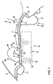
- Fig. 1 is a schematic cross section through an instrument panel 1 in the passenger area 2 of a motor vehicle.
- the instrument panel 1 has a windshield 3 associated front instrument panel wall portion 4 and a in cross section seen through the instrument panel of the windshield 3 away in the direction Vehicle interior 5 adjoining the front instrument panel wall region 4 rear instrument panel wall area 6 as a potential head impact panel wall area on.
- An aeration device 7 has one with a not shown here Air supply device coupled Wegströmer air supply channel 8 for air supply arranged in the instrument panel wall area and not shown here concernedausströmerdüsen on, wherein the employedausströmer air supply channel 8 of the Instrument panel 1 is covered.
- the person vent air supply channel 8 extends in the passenger area 2 below the potential head impact panel wall area 6 and is in a middle Instrument panel region 9 (Fig. 2, 3) via an air inlet opening 10 with the air supply device coupled and from there in approximately straight line in vehicle transverse axis direction led to a peripheral turnedausströmerdüse.
- An outflow opening 11 the personal air outlet air supply channel 8 is a Wegströmerdüse not shown here assigned.
- the passenger air outlet air supply channel 8 in one piece with one with a defroster air supply device coupled defroster air duct 12 formed below the front Instrument panel wall portion 4 substantially along the entire lower Windshield edge area runs.
- the upward directed arrows 13 are shown schematically, are in the windshield 3rd associated, front instrument panel wall portion 4 not shown in detail here Defroster nozzles designed for supplying air from the defroster air duct 12 to Windscreen 3.
- the air supply to the defroster air duct 12 takes place here via a Defroster air inlet opening 14.
- the defroster air passage 12 is in FIG a seen in vehicle transverse axis direction edge region in the vehicle longitudinal direction from the windshield 3 back to the rear instrument panel wall area 6 of there terminating Wegströmer air supply channel 8 led to Defrosting of side window areas via correspondingly associated defroster nozzles, which are not shown in detail here.
- This will, as in particular from the 2 and 3 it can be seen in the area between the passenger air outlet air supply channel. 8 and the defroster air duct 12, a free space 15 designed as a mounting space.
- a lower side wall of the instrument panel 1 forms a Wall of the defroster air duct 12 and the passenger air supply duct 8 from.
- the Mutualausströmer air supply channel 8 and thus outside the potential Head impact panel wall portion 6 may, as in Figs. 1 and 3 is shown schematically and dashed, an airbag module 17 are arranged, the a dashed line shown in Fig. 1 airbag 18 and a not shown here Gas generator as a filling device, which received in an airbag housing 19 are.
- the airbag housing 19 is indirectly via a firing channel or directly, which is here however, not shown, e.g. at least partially on a dashboard underside established.
- the main body 20 is from above by means of a cover 21st covered, which is perforated throughout with a perforation pattern such that over the perforations 22 as air passage openings at least in the region of at least a discharge nozzle a diffuse ventilation is adjustable.
- a recess 23 is provided in the main body 20 .
- the airbag 18 then pushes with its high initial Filling pressure of e.g. 30 bar on the cover flap 24 to release the airbag outlet opening 25th
- 25 retaining means in the region of the airbag outlet opening be provided, such. a tether, the Aufschwenkwinkel the cover 24 limit what is not shown here.
- a specific Anstellwinkel the cover flap 24 a certain direction of inflation of the airbag 18 in Direction vehicle interior 5 can be specified.
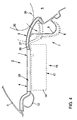
- branch channels 26 are starting from the person air outlet air supply channel 8, for example, two branch channels 26 here in the front instrument panel wall portion 4 and there in the area below the Perforations 22 out.
- the Stitch channels 26 so in the region of the perforations 22 in the front instrument panel wall area 4 that these seen from above the airbag module 17 is not cover.
- branch channels 26 is a simple air supply to the Perforations 22 created for the diffuse ventilation of the vehicle interior 5.
- the potential Head impact area as the rear instrument panel wall portion 6 partly from a lower Energy absorption deformable material, e.g. from one with one Slush skin 27 coated energy absorption foam backing layer 28.
- a deformation space 29 formed in which the potential Head impact region of the instrument panel 1, as shown in FIG. 4 only schematically and dashed lines shown in a collision of a vehicle occupant with a head 30 below Energy absorption can deform unhindered.
- the formable in this front instrument panel wall portion 4 Airbag outlet opening 25 has a predetermined safety distance 35 to the rear Instrument panel wall area 6 as a potential head impact panel wall area of the head 30 of a vehicle occupant.
- the safety distance 35 is here specified that the airbag 18 after a feed path in the direction of the vehicle interior 5, the safety distance 35 between the airbag outlet opening 25 and the potential head impact panel wall area 6 corresponds to a gas pressure as Filling pressure compared to the initial gas pressure in the airbag 18 at the beginning of Airbag activation according to predetermined limits is reduced.
- the safety distance is 35 in Preferably, the cross-section is approximately the straight-line, shortest connection between the particularly critical and potential head impact area and the beginning of the Airbag outlet opening 25.
- the high initial filling pressure of about 30 bar is especially at first Centimeters, i. especially after a feed distance of about 100 mm already on reduces a pressure of about 3 bar.
- a feed of 120 mm is achieved in about a pressure of about 2 bar in the airbag, the at the end of the Inflation process in the airbag existing negative pressure corresponds. That means that already at a safety distance of about 120 mm through the filling process and the so accompanying high inflation pressure existing airbag aggressiveness is significantly reduced.
- This can be depending on the given installation conditions, for example, already from a safety distance of about 100 mm between the airbag outlet opening 25 and the head impact area a significant reduction of the risk of injury in itself out-of-position vehicle occupants, e.g. Children, achieve because the aggressiveness the airbag 18 after passing through the safety distance 35, by the high initial filling pressure is reduced, is almost reduced to the minimum value.
Landscapes
- Engineering & Computer Science (AREA)
- Mechanical Engineering (AREA)
- Physics & Mathematics (AREA)
- Thermal Sciences (AREA)
- Air Bags (AREA)
- Instrument Panels (AREA)
- Air-Conditioning For Vehicles (AREA)
- Processing Of Solid Wastes (AREA)
Abstract
Description
Ein besonders vorteilhafter und materialsparender Aufbau ergibt sich, wenn ein Unterseitenwandbereich der Instrumententafel Bestandteil der Luftzufuhrkanalwand ist.
- Fig. 1
- einen schematischen Querschnitt durch eine Instrumententafel im Beifahrerbereich,
- Fig. 2
- eine schematische, perspektivische Darstellung des Beifahrerbereichs eines mit einem Defroster-Luftkanal kombinierten Personenausströmer-Luftzufuhrkanals,
- Fig. 3
- eine schematische Draufsicht auf die Darstellung gemäß Fig. 2,
- Fig. 4
- einen schematischen Querschnitt durch die Instrumententafel im Beifahrerbereich gemäß Fig. 1 mit strichliert eingezeichnetem, potentiellen Kopfaufprallfall,
- Fig. 5
- einen schematischen Querschnitt durch eine Instrumententafel im Beifahrerbereich gemäß Fig. 1 mit einer alternativen Situation eines Kopfaufprallfall,
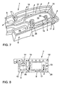
- Fig. 6
- einen schematischen Querschnitt durch eine Instrumententafel im Beifahrerbereich, wobei der Schnittverlauf durch einen Stichkanal zu einer diffusen Belüftung gewählt ist,
- Fig. 7
- eine schematische, perspektivische Darstellung eines beifahrerseitigen Personenausströmer-Luftzufuhrkanals mit kombiniertem Defroster-Luftkanal und beispielhaft dargestellten Stichkanälen von dem Personenausströmer-Luftzufuhrkanal weg,
- Fig. 8
- eine schematische Draufsicht entsprechend Fig. 7,
- Fig. 9
- einen schematischen Querschnitt durch eine Instrumententafel im Beifahrerbereich gemäß dem Stand der Technik,
- Fig. 10
- eine schematische, perspektivische Darstellung eines mit einem Defroster-Luftkanal kombinierten Personenausströmer-Luftzufuhrkanals gemäß dem Stand der Technik im Beifahrerbereich,
- Fig.11
- eine schematische Draufsicht auf die Fig. 10 gemäß dem Stand der Technik.
- 1
- Instrumententafel
- 2
- Beifahrerbereich
- 3
- Windschutzscheibe
- 4
- vorderer Instrumententafelwandbereich
- 5
- Fahrzeuginnenraum
- 6
- hinterer Instrumententafelwandbereich
- 7
- Belüftungsvorrichtung
- 8
- Personenausströmer-Luftzufuhrkanal
- 9
- mittlerer Instrumententafelbereich
- 10
- Lufteintrittsöffnung
- 11
- Ausströmöffnung
- 12
- Defroster-Luftkanal
- 13
- Pfeile
- 14
- Defroster-Lufteintrittsöffnung
- 15
- Freiraum
- 16
- Schweißverbindungsflächen
- 17
- Airbagmodul
- 18
- Airbag
- 19
- Airbaggehäuse
- 20
- Grundkörper
- 21
- Abdeckung
- 22
- Perforierung
- 23
- Aussparung
- 24
- Abdeckklappe
- 25
- Airbagaustrittsöffnung
- 26
- Stichkanal
- 27
- Slushhaut
- 28
- Energieabsorptionsschaum-Trägerschicht
- 29
- Deformationsraum
- 30
- Kopf
- 31
- Gasgenerator-Gehäusebereich
- 32
- Airbag-Gehäusebereich
- 33
- Sollbruchstellen
- 34
- Pfeil
- 35
- Sicherheitsabstand
- 100
- Instrumententafel
- 101
- Belüftungsvorrichtung
- 102
- Beifahrerbereich
- 103
- Windschutzscheibe
- 104
- vordere Instrumententafelwandbereich
- 105
- Fahrzeuginnenraum
- 106
- hinterer Instrumententafelwandbereich
- 107
- Personenausströmer-Luftzufuhrkanal
- 108
- Defroster-Luftkanal
- 109
- Schweißverbindungsflächen
- 110
- Aufnahmeraum
- 111
- Airbagmodul
Claims (18)
- Belüftungsvorrichtung für ein Fahrzeug, insbesondere für ein Kraftfahrzeug, mit einer Instrumententafel (1), die im Beifahrerbereich einen einer Windschutzscheibe (3) zugeordneten vorderen Instrumententafelwandbereich (4) und einen sich im Querschnitt durch die Instrumententafel gesehen von der Windschutzscheibe weg in Richtung Fahrzeuginnenraum an den vorderen Instrumententafelwandbereich hin anschließenden, einem Beifahrer zugeordneten hinteren Instrumententafelwandbereich (6) als potentiellen Kopfaufprall-Instrumententafelwandbereich aufweist,
mit einem mit einer Luftversorgungseinrichtung (7) gekoppelten Personenausströmer-Luftzufuhrkanal (8) zur Luftzuführung zu im Instrumententafelwandbereich angeordneten Personenausströmerdüsen, wobei der Personenausströmer-Luftzufuhrkanal (8) von der Instrumententafel überdeckt ist,
mit einem Airbagmodul (17), das wenigstens einen Airbag (18) und wenigstens einen Gasgenerator aufweist, die in einem Airbaggehäuse (19) aufgenommen sind, wobei das Airbagmodul (17) im montierten Zustand von der Instrumententafel überdeckt ist,
wobei der Personenausströmer-Luftzufuhrkanal (8) im Beifahrerbereich unterhalb des potentiellen Kopfaufprall-Instrumententafelwandbereichs (4) verläuft und sich dort im wesentlichen in Fahrzeugquerachsenrichtung erstreckt, und
wobei das Airbagmodul (17) im Beifahrerbereich in Fahrzeuglängsachsenrichtung gesehen in einem Freiraum vor dem Personenausströmer-Luftzufuhrkanal(8) angeordnet und damit im wesentlichen außerhalb des potentiellen Kopfaufprall-Instrumententafelwandbereichs, dem vorderen Instrumententafelwandbereich (4) zugeordnet, angeordnet ist,
dadurch gekennzeichnet, dass der der Windschutzscheibe (3) zugewandte vordere Instrumententafelwandbereich (4) wenigstens bereichsweise Luftdurchtrittsöffnungen (22) zur diffusen Belüftung des Fahrzeuginnenraums (5) aufweist, und
dass vom Personenauströmer-Luftzufuhrkanal (8) ausgehend wenigstens ein Stichkanal (26) in den Bereich unterhalb der Luftdurchtrittsöffnungen (22) geführt ist. - Belüftungsvorrichtung nach Anspruch 1, dadurch gekennzeichnet, dass der Personenausströmer-Luftzufuhrkanal (8) in einem in Fahrzeugquerachsenrichtung gesehen mittleren Instrumententafelbereich (9) mit der Luftversorgungseinrichtung gekoppelt ist und von dort aus in etwa geradlinig in Fahrzeugquerachsenrichtung zu wenigstens einer randseitigen Personenausströmerdüse geführt ist.
- Belüftungsvorrichtung nach Anspruch 1 oder Anspruch 2, dadurch gekennzeichnet, dass der Personenausströmer-Luftzufuhrkanal (8) integral mit der Instrumententafelunterseite ausgebildet ist oder durch eine Schraub- und/oder Klipp- und/oder Schweißverbindung im wesentlichen luftdicht an der Instrumententafelunterseite festgelegt ist.
- Belüftungsvorrichtung nach einem der Ansprüche 1 bis 3, dadurch gekennzeichnet, dass ein Unterseitenwandbereich der Instrumententafel Bestandteil der Personenausströmer-Luftzufuhrkanalwand ist.
- Belüftungsvorrichtung nach einem der Ansprüche 1 bis 4, dadurch gekennzeichnet, dass der vom Personenausströmer-Luftzufuhrkanal (22) ausgehende wenigstens eine Stichkanal (26) so in den Bereich der Luftdurchtrittsöffnungen (22) im vorderen Instrumententafelwandbereich (4) geführt ist, dass dieser das im in Fahrzeuglängsachsenrichtung gesehenen Freiraum (15) vor dem Personenausströmer-Luftzufuhrkanal (8) angeordnete Airbagmodul (17) von oben her nicht überdeckt.
- Belüftungsvorrichtung nach einem der Ansprüche 1 bis 5, dadurch gekennzeichnet, dass in einem tragenden Grundkörper (20) des vorderen Instrumententafelwandbereichs (4) wenigstens eine Ausströmdüse integriert ist, die mit dem wenigstens einen Stichkanal (26) verbunden ist.
- Belüftungsvorrichtung nach Anspruch 6, dadurch gekennzeichnet, dass der Grundkörper (20) von oben her mittels einer Abdeckung (21) abgedeckt ist, die durchgehend perforiert ist mit einem Perforationsmuster dergestalt, dass über die Perforierungen (22) als Luftdurchtrittsöffnungen im Bereich der wenigstens einen Ausströmdüse eine diffuse Belüftung einstellbar ist.
- Belüftungsvorrichtung nach einem der Ansprüche 1 bis 7, dadurch gekennzeichnet, dass ein mit einer Defroster-Luftversorgungseinrichtung (12) gekoppelter Defroster-Luftkanal vorgesehen ist, der unterhalb des vorderen Instrumententafelwandbereichs (4) entlang des gesamten unteren Windschutzscheibenrandbereichs verläuft, und dass im vorderen Instrumententafelwandbereich (4) Defrosterdüsen ausgebildet sind zur Zuführung von Luft vom Defroster-Luftkanal (12) zur Windschutzscheibe (3).
- Belüftungsvorrichtung nach Anspruch 8, dadurch gekennzeichnet, dass der Defroster-Luftkanal (12) in einem in Fahrzeugquerachsenrichtung gesehenen Randbereich in Fahrzeuglängsachsenrichtung gesehen von der Windschutzscheibe (3) weg nach hinten in den hinteren Instrumententafelwandbereich (6) des dort endenden Personenausströmer-Luftzufuhrkanals (8) geführt ist zum Defrosten von Seitenscheibenbereichen über entsprechend zugeordnete Defrosterdüsen, so dass im Bereich zwischen dem Personenausströmer-Luftzufuhrkanal (8) und dem Defroster-Luftkanal (12) der Freiraum (15) als Montageraum für das Airbagmmodul (17) wenigstens bereichsweise eingeschlossen ist.
- Belüftungsvorrichtung nach einem der Ansprüche 1 bis 9, dadurch gekennzeichnet, dass der potentielle Kopfaufprall-Instrumententafelwandbereich (6) der Instrumententafel (1) wenigstens bereichsweise aus einem energieabsorbierenden Material hergestellt ist.
- Belüftungsvorrichtung nach Anspruch 10, dadurch gekennzeichnet, dass der potentielle Kopfaufprall-Instrumententafelwandbereich (6) aus einem unter Energieabsorption deformierbaren Material hergestellt ist, und
dass im unterhalb des potentiellen Kopfaufprall-Instrumententafelwandbereichs (6) liegenden Bereich ein Deformationsraum (29) ausgebildet ist dergestalt, dass bei einem Kopfaufprall auf den potentiellen Kopfaufprallbereich dieser Bereich der Instrumententafel (1) unter Energieabsorption ungehindert in den Deformationsraum (29) hinein verformbar ist. - Belüftungsvorrichtung nach Anspruch 10 oder Anspruch 11, dadurch gekennzeichnet, dass der potentielle Kopfaufprall-Instrumententafelwandbereich (6) im wesentlichen aus einer vorzugsweise mit einer Slushhaut (27) überzogenen Trägerschicht (28) aus Energieabsorptionsschaum hergestellt ist.
- Belüftungsvorrichtung nach einem der Ansprüche 1 bis 12, dadurch gekennzeichnet, dass der wenigstens eine Airbag (18) im nicht aktivierten, zusammengefalteten Grundzustand hinter dem der Windschutzscheibe (3) zugeordneten, vorderen Instrumententafelwandbereich (4) als instrumententafelseitigem Airbagaustrittwandbereich angeordnet ist,
dass die im vorderen Instrumententafelwandbereich (4) ausbildbare Airbagaustrittöffnung (25) einen vorgebbaren Sicherheitsabstand (35) zu einem potentiellen Kopfaufprallbereich eines Fahrzeuginsassen im sich von der Windschutzscheibe (3) weg in Richtung Fahrzeuginnenraum (5) an den vorderen Instrumententafelwandbereich (4) hin anschließenden Kopfaufprall-Instrumententafelwandbereich (6) aufweist, und
dass der Sicherheitsabstand (35) so vorgebbar ist, dass der Airbag (18) nach einem dem Sicherheitsabstand (35) zwischen der Airbagaustrittöffnung (25) und dem potentiellen Kopfaufprallbereich entsprechenden Vorschubweg in Richtung Fahrzeuginnenraum (5) einen Fülldruck aufweist, der gegenüber dem anfänglichen Fülldruck im Airbag (18) zu Beginn der Airbagaktivierung entsprechend vorgebbarer Grenzwerte reduziert ist. - Belüftungsvorrichtung nach Anspruch 13, dadurch gekennzeichnet, dass der Sicherheitsabstand (35) so festgelegt ist, dass der Fülldruck im Airbag (18) nach einem Vorschubweg des Airbags (18) entsprechend dem Sicherheitsabstand (35) im potentiellen Kopfaufprallbereich höchstens in etwa 15 %, bevorzugt höchstens in etwa 10 %, höchst bevorzugt höchstens in etwa 5 % des anfänglichen Gasdrucks beträgt.
- Belüftungsvorrichtung nach Anspruch 13 oder Anspruch 14, dadurch gekennzeichnet, dass der Sicherheitsabstand (35) in Abhängigkeit von der jeweiligen Aufprallsituation wenigstens in etwa 10 cm, bevorzugt wenigstens in etwa 15 cm, höchst bevorzugt wenigstens in etwa 20 cm beträgt.
- Belüftungsvörrichtung nach einem der Ansprüche 13 bis 15, dadurch gekennzeichnet, dass der Airbag (18) einen anfänglichen Fülldruck zwischen in etwa 30 bar und 35 bar aufweist und der Fülldruck nach einem Vorschubweg von in etwa 100 mm in etwa 2,5 bis 3,5 bar und vorzugsweise nach einem Vorschubweg von in etwa 200 mm in etwa 1,5 bis 2,5 bar beträgt.
- Belüftungsvorrichtung nach einem der Ansprüche 13 bis 16, dadurch gekennzeichnet, dass der Sicherheitsabstand (35) im Querschnitt durch die Instrumententafel (1) gesehen in etwa die geradlinige kürzeste Verbindung zwischen dem der Airbagaustrittöffnung (25) zugewandten Beginn des potentiellen Kopfaufprallbereichs und dem dem potentiellen Kopfaufprallbereich zugewandten Beginn der Airbagaustrittöffnung (25) ist.
- Belüftungsvorrichtung nach einem der Ansprüche 1 bis 17, dadurch gekennzeichnet, dass das Airbaggehäuse (19) so ausgebildet ist, dass der darin aufgenommene wenigstens eine Airbag (18) im montierten Grundzustand seitlich neben dem wenigstens einen Gasgenerator angeordnet ist, und/oder
dass im Verbindungsbereich zwischen einem den Gasgenerator aufnehmenden Gasgenerator-Gehäusebereich (31) und einem den Airbag (18) aufnehmenden Airbag-Gehäusebereich (32) wenigstens eine Materialschwächung und/oder Sollbruchstelle (33) vorgesehen ist, die bei einer Krafteinwirkung auf einen der beiden Gehäuseteile (31), insbesondere bei einer Krafteinwirkung auf den wenigstens bereichsweise in einen deformierbar gestalteten, potentiellen Kopfaufprallbereich der Instrumententafel (1) ragenden Gasgenerator-Gehäusebereich (31), bricht und ein auf Block gehen des Deformationsbereiches verhindert.
Applications Claiming Priority (5)
| Application Number | Priority Date | Filing Date | Title |
|---|---|---|---|
| DE10150660 | 2001-10-17 | ||
| DE10150660 | 2001-10-17 | ||
| DE10163685 | 2001-12-21 | ||
| DE2001163685 DE10163685A1 (de) | 2001-12-21 | 2001-12-21 | Belüftungsvorrichtung für ein Fahrzeug, insbesondere für ein Kraftfahrzeug |
| PCT/EP2002/009192 WO2003033310A1 (de) | 2001-10-17 | 2002-08-16 | Fahrzeugbelüftungsvorrichtung, insbesondere für ein kraftfahrzeug |
Publications (2)
| Publication Number | Publication Date |
|---|---|
| EP1439986A1 EP1439986A1 (de) | 2004-07-28 |
| EP1439986B1 true EP1439986B1 (de) | 2005-04-06 |
Family
ID=26010372
Family Applications (1)
| Application Number | Title | Priority Date | Filing Date |
|---|---|---|---|
| EP02774520A Expired - Lifetime EP1439986B1 (de) | 2001-10-17 | 2002-08-16 | Fahrzeugbelüftungsvorrichtung, insbesondere für ein kraftfahrzeug |
Country Status (6)
| Country | Link |
|---|---|
| US (1) | US7364187B2 (de) |
| EP (1) | EP1439986B1 (de) |
| JP (1) | JP2006515058A (de) |
| CN (1) | CN1309595C (de) |
| DE (1) | DE50202735D1 (de) |
| WO (1) | WO2003033310A1 (de) |
Families Citing this family (14)
| Publication number | Priority date | Publication date | Assignee | Title |
|---|---|---|---|---|
| DE10253185A1 (de) * | 2002-11-15 | 2004-06-03 | Autoliv Development Ab | Instrumententafel für ein Kraftfahrzeug mit einer in einer Lüftungsanordnung integrierten Airbageinrichtung |
| KR100558916B1 (ko) * | 2003-11-12 | 2006-03-10 | 현대자동차주식회사 | 차량의 동승석 인비져블 에어백 장치 |
| DE10360584B4 (de) * | 2003-12-19 | 2012-11-15 | Johnson Controls Interiors Gmbh & Co. Kg | Armaturentafel für ein Kraftfahrzeug |
| EP1808364B1 (de) * | 2006-01-16 | 2011-08-24 | Ford Global Technologies, LLC | Kraftfahrzeug vordere innere Struktur |
| US7537239B2 (en) * | 2006-10-25 | 2009-05-26 | Ford Global Technologies, Llc | Seamless airbag ring with integrated duct mount |
| DE102008047690A1 (de) * | 2008-09-18 | 2010-03-25 | GM Global Technology Operations, Inc., Detroit | Fahrzeuginnenverkleidung und Temperierungsverfahren |
| DE102012107230B4 (de) | 2012-08-07 | 2022-01-05 | Hanon Systems | Anordnung von Luftauslässen an einem Kraftfahrzeugklimagerät |
| CN103868481A (zh) * | 2012-12-18 | 2014-06-18 | 北汽福田汽车股份有限公司 | 校核仪表板出风口的方法 |
| US10787154B2 (en) | 2016-09-07 | 2020-09-29 | Ford Global Technologies, Llc | Windshield defroster with secondary ducted outlet |
| US20190045117A1 (en) * | 2017-08-03 | 2019-02-07 | Ford Global Technologies, Llc | Panoramic display screen assembly with integral ventilation passageways |
| US11214125B2 (en) | 2017-11-06 | 2022-01-04 | Taylor Made Group, Llc | Closable air vent |
| KR20210091658A (ko) * | 2018-03-13 | 2021-07-22 | 마힌드라 앤드 마힌드라 리미티드 | 차량의 은폐형 에어 벤트 장치 및 그 방법 |
| JP7231460B2 (ja) * | 2019-04-01 | 2023-03-01 | 三菱重工サーマルシステムズ株式会社 | 空気吹出装置 |
| CN113928259B (zh) * | 2021-09-01 | 2023-06-06 | 浙江吉利控股集团有限公司 | 一种车辆碰撞缓冲装置及车辆 |
Family Cites Families (34)
| Publication number | Priority date | Publication date | Assignee | Title |
|---|---|---|---|---|
| US3922429A (en) * | 1971-11-03 | 1975-11-25 | Gen Tire & Rubber Co | Composite impact absorbing safety structure |
| US3817552A (en) * | 1972-08-25 | 1974-06-18 | Gen Motors Corp | Occupant restraint system |
| DE3806783A1 (de) * | 1988-03-02 | 1989-09-14 | Kiss G H | Instrumententafel |
| US5087067A (en) * | 1989-05-19 | 1992-02-11 | Honda Giken Kogyo Kabushiki Kaisha | Inflatable bag assembly for protecting a vehicle occupant |
| FR2661883B1 (fr) * | 1990-05-11 | 1992-07-17 | Renault | Structure plastique de separation entre l'habitacle et le compartiment moteur d'un vehicule automobile. |
| JP2528375B2 (ja) * | 1990-06-18 | 1996-08-28 | 本田技研工業株式会社 | 乗員保護用エアバッグ装置 |
| JPH0455146A (ja) * | 1990-06-23 | 1992-02-21 | Mazda Motor Corp | 自動車のインストルメントパネル内の組付方法 |
| JPH05139237A (ja) * | 1991-06-28 | 1993-06-08 | Daihatsu Motor Co Ltd | 助手席用エアバツグモジユールの取付け構造 |
| JPH05270345A (ja) * | 1992-03-25 | 1993-10-19 | Takata Kk | 助手席用エアバッグ装置 |
| US5342082A (en) * | 1993-05-28 | 1994-08-30 | Morton International, Inc. | Airbag reaction canister having softened edges |
| DE4418582C2 (de) | 1993-09-29 | 2000-10-26 | Daimler Chrysler Ag | Instrumententafel in einem Kraftwagen |
| EP0646500B1 (de) * | 1993-09-29 | 1997-06-18 | Mercedes-Benz Ag | Instrumententafel für ein Kraftfahrzeug |
| DE4338099C2 (de) | 1993-11-08 | 1996-01-25 | Daimler Benz Ag | Einrichtung zum Zuführen von Luft in die Fahrgastzelle von Fahrzeugen |
| IT1267628B1 (it) | 1994-11-25 | 1997-02-07 | Fiat Ricerche | Dispositivo di climatizzazione per un autoveicolo. |
| GB9423776D0 (en) * | 1994-11-25 | 1995-01-11 | Acg Deutschland Gmbh | Dashboard assembly |
| US5505484A (en) * | 1995-02-23 | 1996-04-09 | Morton International, Inc. | Collapsible airbag canister |
| DE19508983C1 (de) * | 1995-03-13 | 1996-02-15 | Daimler Benz Ag | Vorrichtung zur diffusen Belüftung |
| US5533747A (en) * | 1995-06-15 | 1996-07-09 | Morton International, Inc. | Airbag module with collapsible side wall |
| DE19626441B4 (de) | 1996-06-20 | 2004-03-25 | Sommer-Allibert-Lignotock Gmbh | Cockpit für Kraftfahrzeuge |
| JP3230146B2 (ja) * | 1996-09-30 | 2001-11-19 | 豊田合成株式会社 | 乗員拘束装置 |
| FR2759027B1 (fr) * | 1997-02-05 | 1999-04-09 | Valeo Climatisation | Conduit d'air integre pour planche de bord de vehicule automobile |
| DE19720384C1 (de) | 1997-05-15 | 1998-06-04 | Daimler Benz Ag | Flächenhaftes Belüftungselement für den Fahrgastraum eines Kraftfahrzeuges |
| JP3724765B2 (ja) * | 1997-11-26 | 2005-12-07 | 富士重工業株式会社 | インストルメントパネル構造 |
| DE19807259B4 (de) | 1998-02-20 | 2007-09-13 | Volkswagen Ag | Belüftungsanlage mit Defrosterdüse |
| JP3405182B2 (ja) * | 1998-03-27 | 2003-05-12 | 豊田合成株式会社 | 助手席用エアバッグ装置 |
| JP3542288B2 (ja) * | 1998-10-07 | 2004-07-14 | 森六株式会社 | 自動車におけるインストルメントパネル支持構造 |
| FR2796612B1 (fr) | 1999-07-23 | 2001-10-12 | Plastic Omnium Valeo Interiors | Tableau de bord notamment pour vehicule automobile |
| US6286858B1 (en) * | 1999-07-29 | 2001-09-11 | Delphi Technologies, Inc. | Energy absorbing air bag module |
| FR2799157B1 (fr) * | 1999-10-05 | 2001-12-14 | Valeo Climatisation | Installation de climatisation pour vehicule avec diffusion douce |
| FR2799413B1 (fr) * | 1999-10-06 | 2002-07-12 | Valeo Climatisation | Installation de chauffage et/ou climatisation pour vehicule automobile, comportant un systeme de distribution d'air |
| FR2805780B1 (fr) * | 2000-03-06 | 2002-08-09 | Valeo Climatisation | Dispositif de chauffage, ventilation et/ou climatisation comportant au moins un element de diffusion d'air dans l'habitacle d'un vehicule |
| FR2805778B1 (fr) * | 2000-03-06 | 2002-10-11 | Valeo Climatisation | Procede d'aeration d'un habitacle par diffusion douce et dispositif de mise en oeuvre |
| DE20007819U1 (de) * | 2000-05-04 | 2000-07-20 | Reum AG, 74736 Hardheim | Belüftungsvorrichtung für den Innenraum eines Fahrzeugs |
| JP3885711B2 (ja) * | 2002-08-09 | 2007-02-28 | 株式会社デンソー | 空調システム |
-
2002
- 2002-08-16 EP EP02774520A patent/EP1439986B1/de not_active Expired - Lifetime
- 2002-08-16 DE DE50202735T patent/DE50202735D1/de not_active Expired - Lifetime
- 2002-08-16 WO PCT/EP2002/009192 patent/WO2003033310A1/de not_active Ceased
- 2002-08-16 JP JP2003536067A patent/JP2006515058A/ja active Pending
- 2002-08-16 CN CNB028207130A patent/CN1309595C/zh not_active Expired - Fee Related
-
2004
- 2004-04-19 US US10/827,652 patent/US7364187B2/en not_active Expired - Fee Related
Also Published As
| Publication number | Publication date |
|---|---|
| CN1309595C (zh) | 2007-04-11 |
| WO2003033310A8 (de) | 2004-05-13 |
| EP1439986A1 (de) | 2004-07-28 |
| CN1571740A (zh) | 2005-01-26 |
| WO2003033310A1 (de) | 2003-04-24 |
| US7364187B2 (en) | 2008-04-29 |
| DE50202735D1 (de) | 2005-05-12 |
| JP2006515058A (ja) | 2006-05-18 |
| US20040214517A1 (en) | 2004-10-28 |
Similar Documents
| Publication | Publication Date | Title |
|---|---|---|
| EP1439986B1 (de) | Fahrzeugbelüftungsvorrichtung, insbesondere für ein kraftfahrzeug | |
| DE10131120A1 (de) | Baugruppe bestehend aus Fahrzeugkarosserie, Frontscheibe, Instrumententafel und Gassackmodul | |
| DE69710381T2 (de) | Seitenaufprall-Airbag-Vorrichtung | |
| DE112008002575B4 (de) | Stützstruktur für einen Airbag | |
| DE10007343B4 (de) | Sicherheitseinrichtung für die Insassen eines Fahrzeugs, insbesondere für ein Kraftfahrzeug | |
| EP1438218B1 (de) | Airbaganordnung in einem fahrzeug, insbesondere einem kraftfahrzeug | |
| DE2125967B2 (de) | Schutzvorrichtung für den Insassen eines Fahrzeugs | |
| DE19546143A1 (de) | Fahrzeuginsassen-Rückhalteeinrichtung | |
| DE19816080B4 (de) | Sicherheitsvorrichtung für ein Kraftfahrzeug mit einem Airbag, insbesondere einem Beifahrerairbag | |
| DE19745872A1 (de) | Airbageinrichtung | |
| DE10039800B4 (de) | Fahrzeugdach, insbesondere für ein Kraftfahrzeug | |
| DE10061946A1 (de) | Gassackmodul mit Gasführungseinrichtung | |
| DE10253403A1 (de) | Baugruppe bestehend aus Fahrzeugkarosserieteil und einem Gassackmodul | |
| DE10039803B4 (de) | Fahrzeugdach, insbesondere für ein Kraftfahrzeug | |
| DE10019894A1 (de) | Sicherheitseinrichtung für ein Fahrzeug, insbesondere für ein Kraftfahrzeug, mit einem Airbagmodul | |
| DE102006005540A1 (de) | Aufblasbarer Seitenvorhang, der den Kopf des Insassen von der Fahrzeugseitenstruktur weg bewegt | |
| DE10039802B4 (de) | Sicherheitseinrichtung für die Insassen eines Fahrzeugs, insbesondere eines Kraftfahrzeugs | |
| DE10163686A1 (de) | Airbaganordnung in einem Fahrzeug, insbesondere einem Kraftfahrzeug | |
| DE10163685A1 (de) | Belüftungsvorrichtung für ein Fahrzeug, insbesondere für ein Kraftfahrzeug | |
| DE10039807A1 (de) | Kopfstütze, insbesondere für einen Kraftfahrzeugsitz, mit einer Sicherheitseinrichtung | |
| DE102005046651B4 (de) | Energieabsorptionselement, insbesondere Deformationselement, als Sicherheitseinrichtung für Kraftfahrzeuge | |
| DE10036992A1 (de) | Sicherheitssystem für ein Kraftfahrzeug | |
| DE10104456A1 (de) | Sicherheitseinrichtung für ein Fahrzeug, insbesondere für ein Kraftfahrzeug | |
| DE10039801B4 (de) | Fahrzeugdach, insbesondere für ein Kraftfahrzeug | |
| DE10117543A1 (de) | Schiebedach-Sicherheitsvorrichtung mit einer Airbageinrichtung für ein Fahrzeug |
Legal Events
| Date | Code | Title | Description |
|---|---|---|---|
| PUAI | Public reference made under article 153(3) epc to a published international application that has entered the european phase |
Free format text: ORIGINAL CODE: 0009012 |
|
| 17P | Request for examination filed |
Effective date: 20040517 |
|
| AK | Designated contracting states |
Kind code of ref document: A1 Designated state(s): AT BE BG CH CY CZ DE DK EE ES FI FR GB GR IE IT LI LU MC NL PT SE SK TR |
|
| GRAP | Despatch of communication of intention to grant a patent |
Free format text: ORIGINAL CODE: EPIDOSNIGR1 |
|
| GRAS | Grant fee paid |
Free format text: ORIGINAL CODE: EPIDOSNIGR3 |
|
| GRAA | (expected) grant |
Free format text: ORIGINAL CODE: 0009210 |
|
| AK | Designated contracting states |
Kind code of ref document: B1 Designated state(s): CZ DE ES FR GB IT |
|
| PG25 | Lapsed in a contracting state [announced via postgrant information from national office to epo] |
Ref country code: CZ Free format text: LAPSE BECAUSE OF FAILURE TO SUBMIT A TRANSLATION OF THE DESCRIPTION OR TO PAY THE FEE WITHIN THE PRESCRIBED TIME-LIMIT Effective date: 20050406 Ref country code: ES Free format text: LAPSE BECAUSE OF FAILURE TO SUBMIT A TRANSLATION OF THE DESCRIPTION OR TO PAY THE FEE WITHIN THE PRESCRIBED TIME-LIMIT Effective date: 20050406 |
|
| REG | Reference to a national code |
Ref country code: GB Ref legal event code: FG4D Free format text: NOT ENGLISH |
|
| REG | Reference to a national code |
Ref country code: IE Ref legal event code: FG4D Free format text: LANGUAGE OF EP DOCUMENT: GERMAN |
|
| REF | Corresponds to: |
Ref document number: 50202735 Country of ref document: DE Date of ref document: 20050512 Kind code of ref document: P |
|
| GBT | Gb: translation of ep patent filed (gb section 77(6)(a)/1977) |
Effective date: 20050526 |
|
| PLBE | No opposition filed within time limit |
Free format text: ORIGINAL CODE: 0009261 |
|
| STAA | Information on the status of an ep patent application or granted ep patent |
Free format text: STATUS: NO OPPOSITION FILED WITHIN TIME LIMIT |
|
| ET | Fr: translation filed | ||
| 26N | No opposition filed |
Effective date: 20060110 |
|
| REG | Reference to a national code |
Ref country code: FR Ref legal event code: PLFP Year of fee payment: 14 |
|
| REG | Reference to a national code |
Ref country code: FR Ref legal event code: PLFP Year of fee payment: 15 |
|
| PGFP | Annual fee paid to national office [announced via postgrant information from national office to epo] |
Ref country code: IT Payment date: 20160825 Year of fee payment: 15 Ref country code: GB Payment date: 20160831 Year of fee payment: 15 |
|
| PGFP | Annual fee paid to national office [announced via postgrant information from national office to epo] |
Ref country code: FR Payment date: 20160825 Year of fee payment: 15 |
|
| GBPC | Gb: european patent ceased through non-payment of renewal fee |
Effective date: 20170816 |
|
| REG | Reference to a national code |
Ref country code: FR Ref legal event code: ST Effective date: 20180430 |
|
| PG25 | Lapsed in a contracting state [announced via postgrant information from national office to epo] |
Ref country code: GB Free format text: LAPSE BECAUSE OF NON-PAYMENT OF DUE FEES Effective date: 20170816 |
|
| PG25 | Lapsed in a contracting state [announced via postgrant information from national office to epo] |
Ref country code: IT Free format text: LAPSE BECAUSE OF NON-PAYMENT OF DUE FEES Effective date: 20170816 Ref country code: FR Free format text: LAPSE BECAUSE OF NON-PAYMENT OF DUE FEES Effective date: 20170831 |
|
| PGFP | Annual fee paid to national office [announced via postgrant information from national office to epo] |
Ref country code: DE Payment date: 20180831 Year of fee payment: 17 |
|
| REG | Reference to a national code |
Ref country code: DE Ref legal event code: R119 Ref document number: 50202735 Country of ref document: DE |
|
| PG25 | Lapsed in a contracting state [announced via postgrant information from national office to epo] |
Ref country code: DE Free format text: LAPSE BECAUSE OF NON-PAYMENT OF DUE FEES Effective date: 20200303 |