EP1440656A2 - Dispositif pour l'indication visuelle d'une pression sanguine - Google Patents
Dispositif pour l'indication visuelle d'une pression sanguine Download PDFInfo
- Publication number
- EP1440656A2 EP1440656A2 EP04000323A EP04000323A EP1440656A2 EP 1440656 A2 EP1440656 A2 EP 1440656A2 EP 04000323 A EP04000323 A EP 04000323A EP 04000323 A EP04000323 A EP 04000323A EP 1440656 A2 EP1440656 A2 EP 1440656A2
- Authority
- EP
- European Patent Office
- Prior art keywords
- blood
- duct
- blood vessel
- accommodating chamber
- vessel
- Prior art date
- Legal status (The legal status is an assumption and is not a legal conclusion. Google has not performed a legal analysis and makes no representation as to the accuracy of the status listed.)
- Withdrawn
Links
Images




Classifications
-
- A—HUMAN NECESSITIES
- A61—MEDICAL OR VETERINARY SCIENCE; HYGIENE
- A61B—DIAGNOSIS; SURGERY; IDENTIFICATION
- A61B17/00—Surgical instruments, devices or methods
- A61B17/0057—Implements for plugging an opening in the wall of a hollow or tubular organ, e.g. for sealing a vessel puncture or closing a cardiac septal defect
-
- A—HUMAN NECESSITIES
- A61—MEDICAL OR VETERINARY SCIENCE; HYGIENE
- A61B—DIAGNOSIS; SURGERY; IDENTIFICATION
- A61B5/00—Measuring for diagnostic purposes; Identification of persons
- A61B5/02—Detecting, measuring or recording for evaluating the cardiovascular system, e.g. pulse, heart rate, blood pressure or blood flow
- A61B5/021—Measuring pressure in heart or blood vessels
- A61B5/0215—Measuring pressure in heart or blood vessels by means inserted into the body
-
- A—HUMAN NECESSITIES
- A61—MEDICAL OR VETERINARY SCIENCE; HYGIENE
- A61B—DIAGNOSIS; SURGERY; IDENTIFICATION
- A61B17/00—Surgical instruments, devices or methods
- A61B17/0057—Implements for plugging an opening in the wall of a hollow or tubular organ, e.g. for sealing a vessel puncture or closing a cardiac septal defect
- A61B2017/00637—Implements for plugging an opening in the wall of a hollow or tubular organ, e.g. for sealing a vessel puncture or closing a cardiac septal defect for sealing trocar wounds through abdominal wall
-
- A—HUMAN NECESSITIES
- A61—MEDICAL OR VETERINARY SCIENCE; HYGIENE
- A61B—DIAGNOSIS; SURGERY; IDENTIFICATION
- A61B17/00—Surgical instruments, devices or methods
- A61B17/0057—Implements for plugging an opening in the wall of a hollow or tubular organ, e.g. for sealing a vessel puncture or closing a cardiac septal defect
- A61B2017/00646—Type of implements
- A61B2017/00659—Type of implements located only on one side of the opening
-
- A—HUMAN NECESSITIES
- A61—MEDICAL OR VETERINARY SCIENCE; HYGIENE
- A61B—DIAGNOSIS; SURGERY; IDENTIFICATION
- A61B17/00—Surgical instruments, devices or methods
- A61B17/0057—Implements for plugging an opening in the wall of a hollow or tubular organ, e.g. for sealing a vessel puncture or closing a cardiac septal defect
- A61B2017/00672—Locating means therefor, e.g. bleed back lumen
-
- A—HUMAN NECESSITIES
- A61—MEDICAL OR VETERINARY SCIENCE; HYGIENE
- A61B—DIAGNOSIS; SURGERY; IDENTIFICATION
- A61B90/00—Instruments, implements or accessories specially adapted for surgery or diagnosis and not covered by any of the groups A61B1/00 - A61B50/00, e.g. for luxation treatment or for protecting wound edges
- A61B90/06—Measuring instruments not otherwise provided for
- A61B2090/064—Measuring instruments not otherwise provided for for measuring force, pressure or mechanical tension
-
- A—HUMAN NECESSITIES
- A61—MEDICAL OR VETERINARY SCIENCE; HYGIENE
- A61B—DIAGNOSIS; SURGERY; IDENTIFICATION
- A61B5/00—Measuring for diagnostic purposes; Identification of persons
- A61B5/02—Detecting, measuring or recording for evaluating the cardiovascular system, e.g. pulse, heart rate, blood pressure or blood flow
- A61B5/021—Measuring pressure in heart or blood vessels
- A61B5/022—Measuring pressure in heart or blood vessels by applying pressure to close blood vessels, e.g. against the skin; Ophthalmodynamometers
- A61B5/023—Measuring pressure in heart or blood vessels by applying pressure to close blood vessels, e.g. against the skin; Ophthalmodynamometers the pressure transducers comprising a liquid column
-
- Y—GENERAL TAGGING OF NEW TECHNOLOGICAL DEVELOPMENTS; GENERAL TAGGING OF CROSS-SECTIONAL TECHNOLOGIES SPANNING OVER SEVERAL SECTIONS OF THE IPC; TECHNICAL SUBJECTS COVERED BY FORMER USPC CROSS-REFERENCE ART COLLECTIONS [XRACs] AND DIGESTS
- Y10—TECHNICAL SUBJECTS COVERED BY FORMER USPC
- Y10S—TECHNICAL SUBJECTS COVERED BY FORMER USPC CROSS-REFERENCE ART COLLECTIONS [XRACs] AND DIGESTS
- Y10S604/00—Surgery
- Y10S604/90—Telltale showing entry of blood into body inserted conduit
Definitions
- the present invention relates to an indicator device for visually indicating a pulsating pressure of blood flowing inside a blood vessel, and a method, the device and method being usable for verifying correct positioning of a an insertion tube for a wound closure element and of the wound closure element itself inside a blood vessel, in the process of closing a puncture in a blood vessel.
- a system for sealing a percutaneous puncture in a vessel can comprise an inner seal, which is adapted to be positioned against an inner surface of the vessel wall, and a locking member, which is connected to the inner seal by, for example, a filament or a suture and which is adapted to be positioned against an outer surface of the vessel wall, such that the percutaneous puncture is sealed there between.
- the inner seal is folded inside an insertion tube, resting in the puncture to provide access to the inner of the blood vessel. Deployment of the inner seal inside the vessel takes place by pushing the inner seal through the insertion tube, and out from its distal end opening.
- the inner seal has to be deployed some distance away from the puncture hole in the vessel wall before the inner seal is retracted to be securely seated against the inner surface of the vessel wall.
- the insertion tube is retracted out from the puncture, and in the same movement the inner seal is retracted and seated against the inner wall of the blood vessel.
- the locking member is pushed forward through the insertion tube until the locking member is in contact with the outer surface of the vessel wall.
- One method comprises making available a channel for blood to flow in through a distal opening in a dilator, inserted in an introducer sheath, via an opening or port located at a point on said introducer.
- a proximal opening through which blood can flow out, whereby the occurrence or non-occurrence of outflow of blood indicates correct or incorrect position.
- said port is located on the introducer sheath such that blood enters said port only when the tip of the introducer sheath is at a correct position.
- a hollow, thin-walled metal tube typically having a sharp point at its distal end is joined at its proximal end to a transparent viewing section.
- the viewing section has a distal narrow lumen and a proximal chamber which has a cap at its proximal end.
- the cap encloses a pressure sealing means through which a guide wire can be passed.
- the air in the air-tight proximal chamber will alternatively be compressed between diastolic and systolic blood pressure.
- Feedback to the operator that the distal end of the metal tube is properly placed within an artery can be achieved by observing the reciprocating pulsatile motion of the blood column within the distal narrow lumen of the viewing section.
- a guide wire can be passed through the sealing means in the cap, through the viewing section, through the metal tube and finally the guide wire will enter the lumen of the artery.
- a disadvantage with this device is that it will not be usable for all possible pressures that may be encountered. Namely, if blood enters the chamber the meniscus of blood will be located inside the chamber, and fluctuations may not readily be observed, either because the difference in levels between fluctuations is too small, or because the chamber simply cannot be observed.
- the object of the present invention is therefore to provide a means for visual indication that an insertion tube for a wound closure has been correctly positioned inside a blood vessel (i.e. verification of correct position), such that the closure element can be deployed safely and correctly, and whereby less blood flows from the puncture wound than compared to prior art procedures.
- an indicator device/a display device for visually indicating a pulsating pressure of blood flowing inside a blood vessel as claimed in claim 1.
- the device is usable together with a system for deploying and attaching a wound closure member, said device being connectable to an insertion tube of such a system, such that blood from a blood vessel in which the insertion tube is inserted can flow into the display device, for visually displaying the pulsation of the blood flowing into the device, thereby providing the desired verification.
- An indicator device for visually indicating a pressure of blood flowing inside a blood vessel in its most general aspect, comprises a structure, that, as an example, can be provided in the form of a body or handle to be gripped by a user of the device, inside which a duct extends.
- the duct has a distal end and a proximal end.
- a liquid inlet opening is provided at the distal end of the overall structure in fluid communication with the duct.
- the duct can extend all the way up to the distal end of said structure.
- the proximal end is sealed, such that no gas or liquid can escape from the duct at the proximal end.
- the distal end portion of the structure is adapted to be positioned inside said blood vessel.
- the inlet opening can be provided at the very distal tip of the distal end portion of the structure, or at a preferably known distance from said tip.
- the distal portion of the structure can be shaped as a tube which can have a suitable diameter for being inserted into the blood vessel, which will be described more in detail below.
- the tube can be provided as a separate part that is attachable to the body, or it could be integrated with the body to form a unitary structure.
- the structure has an at least semi-transparent section, forming a wall or a window in said duct, for enabling visual observation of liquid entering into said duct via said inlet opening, when said inlet opening is located inside said blood vessel.
- One embodiment of the invention comprises a relatively long, say up to 1 meter, or at least a few decimetres long narrow diameter tubing, the diameter of which suitably is 0,5 - 2 mm, more preferably 1 - 1,5 mm.
- the tubing itself constitutes the "structure", according to the general concept, mentioned above, and the lumen inside the tubing constitutes said duct.
- the tubing suitably is wound around said support element to form a helical structure, in order to reduce the length/ size of the "window" for visual inspection of the pulsating blood. Due to the narrow dimension of the tubing, blood flowing inside the tubing from a blood vessel in which the pressure is slightly higher than atmospheric, will be easily perceptible as it fluctuates or oscillates between two levels in the helix, similar to what was described above.
- the device according to the invention comprises a main body 3 in which there is a gas-filled container or chamber/cavity 4 coupled via a fluid communication pathway 6 to the blood vessel 8.
- the body has a protruding member in the form of a tube 10 having a diameter rendering it suitable for insertion through a percutaneous wound 12 in the blood vessel 8.
- the tube 10 is provided with a side opening 11 for enabling blood to flow into the fluid communication pathway 6, when the insertion tube 10 is located inside the blood vessel 8.
- a narrow duct 14 entering via an aperture 16 into said chamber at a level above the lowest level, i.e. the bottom 17, of said chamber 4, thereby creating a spill-over edge 18 for blood exiting through said aperture 16.
- the duct 14 extends essentially horizontally and is located above the chamber 4, whereby gravity will cause the excess blood to drop down into the chamber.
- Fig. 1 there is also inserted a guide rod 5 in the pathway 6, the function of which is to make insertion of the device into the blood vessel easier.
- This guide rod is subsequently removed when the correct position of the deployment device has been attained and verified using the present invention. After removal the wound closure can be inserted, deployed and attached.
- the duct 14' extends preferably essentially horizontally in the upper region of the main structure (indicated by broken lines in Fig. 1; shown with solid lines in Figs. 2-8) to an opening 16' and a spill-over edge 18'.
- a window 20 (shown by cross-hatching) formed by making the structure at least semi-transparent in this essentially horizontal region enables visual observation of blood flowing in the duct.
- the gas-filled chamber 4 is normally, i.e. in non-operative condition, at atmospheric pressure, and the gas will normally be air, although other gases are possible.
- the device according to the invention is usable together with a system for the safe and correct deployment and positioning of an inner seal of a sealing unit for closing a percutaneous puncture in a blood vessel, whereby the device according to the invention will be used for verification of correct positioning of parts of the system before the inner seal of a wound closure device is deployed inside the vessel.
- a blood vessel sealing unit can comprise an inner seal, which is adapted to be positioned against an inner surface of the blood vessel wall, and a locking member, which is connected to the inner seal by, for example, a filament or a suture and which is adapted to be positioned against an outer surface of the blood vessel wall, such that the percutaneous puncture is sealed there between.
- the inner seal In order that the inner seal shall be capable of covering the puncture, it must have an extension that is larger than the hole. Therefore it must be folded together during passage of the hole, and it must be deployed at a minimum distance from the vessel wall inside the vessel.
- the inner seal is passed through the hole via an insertion tube (corresponding to the tube 10 in fig. 1, however the guide rod 5 shown in Fig. 1 must of course have been removed in order that this be possible), and when it exits the insertion tube at the distal end thereof, it unfolds.
- a preferred distance for deployment although not limited thereto, is about 10 - 20 mm from the vessel wall.
- the inventors have devised the position indicator means according to the present invention, which thus can be coupled to the insertion system/ device.
- a system/device for the insertion/deployment of an inner seal of a wound closure unit generally comprises a body (corresponding to the body 3 shown in fig. 1) provided with at least one passage/lumen/channel 22 for passing devices such as a guide wire (not shown), a guide rod 5 or a dilator (not shown) in and out of the blood vessel 8 (only one of these devices are shown in Fig. 1, namely a guide rod 5).
- An insertion tube 10 can be a separate member coupled to the body such that it attaches to an outlet of said passage/lumen/channel (although in Fig. 1 it is shown as an integrated part of the body 3).
- the indicator device according to the invention is preferably integrated in the body 3.
- the chamber comprises a cavity or chamber 4 inside the body for the accommodation of blood.
- the chamber is in fluid communication with the blood vessel via the insertion tube 10.
- the pressure difference will force blood to flow into the insertion tube 10, via the duct 14, 14' and enter into the cavity 4 in the body 3.
- the blood pressure is low, the blood might not reach all the way to the chamber 4, but will only extend in the duct 14, 14' to some position where it may be observed through the window 20.
- the embodiment of the indicator device according to the invention shown in Figs. 1-7 is integrated with a system for insertion/deployment of an inner seal of a wound closure unit, schematically illustrated in Fig. 1, which shows an initial state just before the distal end of the insertion tube 10 is inserted into the blood vessel 8.
- the guide rod 5 is inserted and extends out from the insertion tube so as to provide for easy entry into the blood vessel 8 through the wound 12. In this stage no blood flows into the side opening 11 in the insertion tube 10.
- Fig. 2 the insertion tube has been inserted into the blood vessel 8 to a point where blood 23 can enter the side opening 11.
- the situation in fig. 2 corresponds to a situation in the heart (pulse) cycle where diastolic pressure prevails.
- the air inside the chamber 4 is slightly compressed but the blood pressure is not high enough to enable the blood to flow all the way into the chamber 4. Instead the meniscus 24 is positioned at a distance from the spill-over edge 18.
- FIG. 3 a situation corresponding to systolic pressure is illustrated.
- the blood has flown in the duct 14 all the way up to the spill-over edge 18', but has not actually flown into the chamber 4.
- the meniscus 25 is located near the edge 18'.
- systolic pressure is high enough that the blood has flown over the spill-over edge 18', and dropped down into the chamber 4, where a pool 24 of blood collects. Blood will continue to flow over the edge 18' until the pressure inside the chamber 4 counterbalances the blood pressure. Then, when the pressure returns to diastolic, the meniscus 26 will withdraw to a position that could resemble the one shown at 27 in Fig. 5.
- the chamber volume is adapted to the expected pressure ranges (systolic pressure ranges approximately between 100 - 200 mm Hg, and diastolic pressure ranges approximately between 60 - 100 mm Hg), such that the lowest possible (or imaginable) systolic pressure (i.e. about 100 mm Hg) would render the meniscus of the blood in the duct visible in the window 20 of the device. Preferably it would extend up to or close to the spill-over edge 18, 18'.
- the highest diastolic pressure i.e. about 100 mm Hg
- the lowest possible systolic pressures would not either be visible in the window, and thus a balance between these two situation must be ascertained.
- One operable embodiment that has been tested has a chamber volume of about 620 mm 3 , and a volume of the duct of about 80 mm 3 , as measured from the exit into the chamber (near the spill-over edge) and to a point corresponding to the location of the blood meniscus as shown in Fig. 5.
- the cycle described above that the system goes through is in effect a self-calibration of the device to set itself up for displaying the meniscus through the window 20 in the body 3, in a state of systolic pressure, and to at least partially withdraw from sight in the window 20 during diastolic pressure.
- the self-calibration is an effect of the relative arrangement of the spill-over edge and the chamber, respectively.
- the inner seal can be deployed at a distance of at least about 10 mm from the vessel wall, in order that the seal be able to unfold properly, before it is retracted to rest against wall.
- the inlet opening 11 is positioned at a distance of 10 mm from the tip of the insertion tube 10.
- the duct 14 can have a varying cross-section over its length.
- the reason for this is that it will be possible to amplify small pressure variations in the beginning of a heart cycle. Namely, by making the duct narrower in the first part, say corresponding to the vertical portion of the duct 14 seen in Fig. 1, or say half of the horizontally extending portion of the duct 14 in Fig. 1, it will be possible to more easily detect a very slight pressure increase.
- the cross-section can be changed stepwise along the duct or continuously changed. The detailed design of the profile of the changing cross-section for a desired purpose can be arrived at with routine experimentation.
- the duct can be made to continuously become narrower towards the spill-over edge, whereby the sensitivity in the detection of pulsation is reduced.
- shaping the duct suitably, i.e. to account for the varying pressure during a cycle, a linear displacement of blood within the window can be achieved. This can be of advantage if the fluctuations are large in or near the systolic pressure region and smaller in other pressure ranges.
- Another option is to let the duct widen in the direction towards the spill-over edge. Widening can be more forgiving, in the sense that it can accommodate a wider pressure range.
- a further preferred embodiment comprises a duct having such dimensions that the meniscus of the blood flowing in the duct always will be essentially perpendicular to the direction of flow. This would be achieved by making the duct thin enough, such that capillary forces will maintain the desired perpendicularity of the meniscus.
- the duct is 2-3 mm thick or less, more preferably the duct is 1 mm thick or less, most suitably 0,5 mm or less.
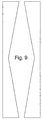
- a suitable width of the duct in the window region could be about 1-5 mm, preferably 2-4 mm, although other dimensions could equally well be suitable for specific purposes.
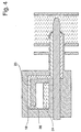
- the prior art device shown in US-5,295,969 can be modified according to the present invention, by extending the lumen 30, by providing a piece of tubing 32 extending into the blood accommodating chamber 34.
- the proximal opening of the tube 32 will form a spill-over edge 36.
- the device will be rotationally symmetric, and the orientation during insertion of the needle into a blood vessel is unimportant.
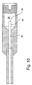
- the insertion tube is normally inserted into the blood vessel at an angle of say 30 - 45° with respect to the extension of the blood vessel in question.
- the two openings are provided as a measure to ascertain that at least one of them will be exposed to the blood inside the vessel.
Landscapes
- Health & Medical Sciences (AREA)
- Life Sciences & Earth Sciences (AREA)
- Cardiology (AREA)
- Surgery (AREA)
- Heart & Thoracic Surgery (AREA)
- Veterinary Medicine (AREA)
- Public Health (AREA)
- General Health & Medical Sciences (AREA)
- Engineering & Computer Science (AREA)
- Biomedical Technology (AREA)
- Animal Behavior & Ethology (AREA)
- Medical Informatics (AREA)
- Molecular Biology (AREA)
- Vascular Medicine (AREA)
- Physiology (AREA)
- Pathology (AREA)
- Biophysics (AREA)
- Physics & Mathematics (AREA)
- Nuclear Medicine, Radiotherapy & Molecular Imaging (AREA)
- Surgical Instruments (AREA)
- Measuring Pulse, Heart Rate, Blood Pressure Or Blood Flow (AREA)
- Infusion, Injection, And Reservoir Apparatuses (AREA)
- Measuring Fluid Pressure (AREA)
Applications Claiming Priority (2)
| Application Number | Priority Date | Filing Date | Title |
|---|---|---|---|
| US43980003P | 2003-01-14 | 2003-01-14 | |
| US439800P | 2003-01-14 |
Publications (2)
| Publication Number | Publication Date |
|---|---|
| EP1440656A2 true EP1440656A2 (fr) | 2004-07-28 |
| EP1440656A3 EP1440656A3 (fr) | 2004-10-06 |
Family
ID=32595349
Family Applications (1)
| Application Number | Title | Priority Date | Filing Date |
|---|---|---|---|
| EP04000323A Withdrawn EP1440656A3 (fr) | 2003-01-14 | 2004-01-09 | Dispositif pour l'indication visuelle d'une pression sanguine |
Country Status (6)
| Country | Link |
|---|---|
| US (3) | US7654963B2 (fr) |
| EP (1) | EP1440656A3 (fr) |
| JP (2) | JP4465198B2 (fr) |
| AU (2) | AU2004200121B2 (fr) |
| DE (1) | DE602004021981D1 (fr) |
| ES (1) | ES2329363T3 (fr) |
Families Citing this family (61)
| Publication number | Priority date | Publication date | Assignee | Title |
|---|---|---|---|---|
| US7662161B2 (en) | 1999-09-13 | 2010-02-16 | Rex Medical, L.P | Vascular hole closure device |
| US6896692B2 (en) | 2000-12-14 | 2005-05-24 | Ensure Medical, Inc. | Plug with collet and apparatus and method for delivering such plugs |
| US6846319B2 (en) | 2000-12-14 | 2005-01-25 | Core Medical, Inc. | Devices for sealing openings through tissue and apparatus and methods for delivering them |
| US6890343B2 (en) | 2000-12-14 | 2005-05-10 | Ensure Medical, Inc. | Plug with detachable guidewire element and methods for use |
| US6623509B2 (en) * | 2000-12-14 | 2003-09-23 | Core Medical, Inc. | Apparatus and methods for sealing vascular punctures |
| US8083768B2 (en) | 2000-12-14 | 2011-12-27 | Ensure Medical, Inc. | Vascular plug having composite construction |
| US20110144661A1 (en) * | 2001-04-24 | 2011-06-16 | Houser Russell A | Tissue closure devices, device and systems for delivery, kits and methods therefor |
| US8992567B1 (en) | 2001-04-24 | 2015-03-31 | Cardiovascular Technologies Inc. | Compressible, deformable, or deflectable tissue closure devices and method of manufacture |
| US20080109030A1 (en) | 2001-04-24 | 2008-05-08 | Houser Russell A | Arteriotomy closure devices and techniques |
| US8961541B2 (en) | 2007-12-03 | 2015-02-24 | Cardio Vascular Technologies Inc. | Vascular closure devices, systems, and methods of use |
| EP1440656A3 (fr) * | 2003-01-14 | 2004-10-06 | Radi Medical Systems Ab | Dispositif pour l'indication visuelle d'une pression sanguine |
| US7850654B2 (en) * | 2003-04-24 | 2010-12-14 | St. Jude Medical Puerto Rico B.V. | Device and method for positioning a closure device |
| US8852229B2 (en) | 2003-10-17 | 2014-10-07 | Cordis Corporation | Locator and closure device and method of use |
| US7361183B2 (en) * | 2003-10-17 | 2008-04-22 | Ensure Medical, Inc. | Locator and delivery device and method of use |
| US7713283B2 (en) * | 2005-04-11 | 2010-05-11 | St. Jude Medical Puerto Rico, Llc | Tissue puncture closure device with magazine fed tamping system |
| US8088144B2 (en) | 2005-05-04 | 2012-01-03 | Ensure Medical, Inc. | Locator and closure device and method of use |
| US8926654B2 (en) * | 2005-05-04 | 2015-01-06 | Cordis Corporation | Locator and closure device and method of use |
| US7837705B2 (en) * | 2005-05-17 | 2010-11-23 | St. Jude Medical Puerto Rico Llc | Tissue puncture closure system with retractable sheath |
| JP4802324B2 (ja) * | 2006-02-22 | 2011-10-26 | 国立大学法人 名古屋工業大学 | 脈診解析のための脈波測定装置 |
| US20070282181A1 (en) * | 2006-06-01 | 2007-12-06 | Carol Findlay | Visual medical sensor indicator |
| US8617204B2 (en) | 2006-09-13 | 2013-12-31 | Accessclosure, Inc. | Apparatus and methods for sealing a vascular puncture |
| US20090112234A1 (en) * | 2007-10-31 | 2009-04-30 | Lawrence Crainich | Reloadable laparoscopic fastener deploying device for use in a gastric volume reduction procedure |
| US8858591B2 (en) | 2007-10-31 | 2014-10-14 | Radi Medical Systems Ab | Method and device for sealing a puncture hole in a bodily organ |
| US8652166B2 (en) | 2007-11-30 | 2014-02-18 | Radi Medical Systems Ab | Insertion tool for a medical closure device |
| US8491629B2 (en) | 2008-02-15 | 2013-07-23 | Rex Medical | Vascular hole closure delivery device |
| US8920463B2 (en) | 2008-02-15 | 2014-12-30 | Rex Medical, L.P. | Vascular hole closure device |
| US8070772B2 (en) | 2008-02-15 | 2011-12-06 | Rex Medical, L.P. | Vascular hole closure device |
| US9226738B2 (en) | 2008-02-15 | 2016-01-05 | Rex Medical, L.P. | Vascular hole closure delivery device |
| US20110029013A1 (en) | 2008-02-15 | 2011-02-03 | Mcguckin James F | Vascular Hole Closure Device |
| US8920462B2 (en) | 2008-02-15 | 2014-12-30 | Rex Medical, L.P. | Vascular hole closure device |
| EP3821817A3 (fr) * | 2008-11-12 | 2021-11-03 | Access Closure, Inc. | Appareil de fermeture d'une perforation vasculaire |
| US8529598B2 (en) | 2009-02-20 | 2013-09-10 | Boston Scientific Scimed, Inc. | Tissue puncture closure device |
| US8052914B2 (en) | 2009-02-20 | 2011-11-08 | Boston Scientific Scimed, Inc. | Modified plug for arteriotomy closure |
| US8375553B2 (en) | 2009-02-20 | 2013-02-19 | Boston Scientific Scimed, Inc. | Locking element for vascular closure device |
| US8317824B2 (en) | 2009-02-20 | 2012-11-27 | Boston Scientific Scimed, Inc. | Tissue puncture closure device |
| US9913634B2 (en) | 2009-02-20 | 2018-03-13 | Boston Scientific Scimed, Inc. | Locking element for vascular closure device |
| US8292918B2 (en) | 2009-02-20 | 2012-10-23 | Boston Scientific Scimed, Inc. | Composite plug for arteriotomy closure and method of use |
| CN104739461A (zh) * | 2009-04-09 | 2015-07-01 | 心血管科技股份有限公司 | 组织封闭装置、输送装置和系统、用于其的套件和方法 |
| US9028466B2 (en) * | 2009-06-08 | 2015-05-12 | St. Jude Medical Coordination Center Bvba | Adapter for use in connecting to a first percutaneous introducer |
| US8469944B2 (en) * | 2009-11-03 | 2013-06-25 | Radi Medical Systems Ab | Introducer access assembly |
| WO2011056125A1 (fr) * | 2009-11-03 | 2011-05-12 | St. Jude Medical Systems Ab | Ensemble d'accès d'introducteur |
| EP2533698B1 (fr) | 2010-02-11 | 2018-03-28 | Boston Scientific Scimed, Inc. | Dispositifs automatiques de déploiement de fermeture vasculaire |
| US8727570B2 (en) * | 2010-02-16 | 2014-05-20 | Martin Professional A/S | Belt tensioning means integrated into illumination device shell part |
| JP5615030B2 (ja) * | 2010-04-30 | 2014-10-29 | 日本コヴィディエン株式会社 | シリンジ及びそのシリンジを有するカテーテルセット |
| US8597340B2 (en) | 2010-09-17 | 2013-12-03 | Boston Scientific Scimed, Inc. | Torque mechanism actuated bioabsorbable vascular closure device |
| US8758402B2 (en) | 2010-12-17 | 2014-06-24 | Boston Scientific Scimed, Inc. | Tissue puncture closure device |
| AU2012262258B2 (en) | 2011-05-31 | 2015-11-26 | Lightlab Imaging, Inc. | Multimodal imaging system, apparatus, and methods |
| US10648918B2 (en) | 2011-08-03 | 2020-05-12 | Lightlab Imaging, Inc. | Systems, methods and apparatus for determining a fractional flow reserve (FFR) based on the minimum lumen area (MLA) and the constant |
| US10485524B2 (en) | 2011-10-25 | 2019-11-26 | Essential Medical, Inc. | Instrument and methods for surgically closing percutaneous punctures |
| US9757104B2 (en) | 2012-07-19 | 2017-09-12 | Essential Medical, Inc. | Multi-lumen tamper tube |
| US10639019B2 (en) | 2013-03-15 | 2020-05-05 | Arrow International, Inc. | Vascular closure devices and methods of use |
| US10154835B2 (en) | 2013-05-09 | 2018-12-18 | Essential Medical, Inc. | Vascular closure device with conforming plug member |
| US10448937B2 (en) | 2013-12-23 | 2019-10-22 | Essential Medical, Inc. | Vascular closure device |
| CN111938616B (zh) | 2014-04-04 | 2024-12-31 | 圣犹达医疗系统公司 | 血管内压力和流量数据诊断系统、设备和方法 |
| US10555727B2 (en) | 2015-06-26 | 2020-02-11 | Essential Medical, Inc. | Vascular closure device with removable guide member |
| FR3059961B1 (fr) * | 2016-12-13 | 2019-10-18 | Valeo Systemes D'essuyage | Adaptateur pour balai d'essuie glace |
| US11504105B2 (en) | 2019-01-25 | 2022-11-22 | Rex Medical L.P. | Vascular hole closure device |
| WO2021192964A1 (fr) * | 2020-03-23 | 2021-09-30 | テルモ株式会社 | Aiguille de perforation et ensemble cathéter |
| US12390249B2 (en) | 2020-07-31 | 2025-08-19 | Teleflex Life Sciences Llc | Access sheath with valve assembly |
| US12383246B2 (en) | 2020-10-12 | 2025-08-12 | Abbott Cardiovascular Systems, Inc. | Vessel closure device with improved safety and tract hemostasis |
| CN118542703B (zh) * | 2024-07-30 | 2024-11-12 | 苏州书秀世医疗器械有限公司 | 一种用于穿刺孔部署填充物的填充物输送控制装置 |
Family Cites Families (53)
| Publication number | Priority date | Publication date | Assignee | Title |
|---|---|---|---|---|
| US2748769A (en) * | 1953-02-24 | 1956-06-05 | Huber Jennie | Hypodermic needle |
| US3062202A (en) * | 1960-03-25 | 1962-11-06 | Hyman Chester | Body fluid pressure measuring device |
| US3730168A (en) * | 1970-09-10 | 1973-05-01 | Kendall & Co | Manometer |
| US3760627A (en) | 1971-12-13 | 1973-09-25 | Richline Co Inc | Rivet gun |
| JPS50139588A (fr) * | 1974-04-23 | 1975-11-07 | ||
| USRE34021E (en) * | 1985-11-18 | 1992-08-04 | Abbott Laboratories | Percutaneous fixation of hollow organs |
| US4767408A (en) * | 1986-03-24 | 1988-08-30 | Taut, Inc. | Flashback structure |
| US4796612A (en) | 1986-08-06 | 1989-01-10 | Reese Hewitt W | Bone clamp and method |
| USRE34866E (en) * | 1987-02-17 | 1995-02-21 | Kensey Nash Corporation | Device for sealing percutaneous puncture in a vessel |
| US4894052A (en) * | 1988-08-22 | 1990-01-16 | Becton, Dickinson And Company | Flash detection in an over the needle catheter with a restricted needle bore |
| US5098433A (en) | 1989-04-12 | 1992-03-24 | Yosef Freedland | Winged compression bolt orthopedic fastener |
| NL8901350A (nl) | 1989-05-29 | 1990-12-17 | Wouter Matthijs Muijs Van De M | Afsluitsamenstel. |
| US5620461A (en) * | 1989-05-29 | 1997-04-15 | Muijs Van De Moer; Wouter M. | Sealing device |
| JPH0634780B2 (ja) | 1989-11-30 | 1994-05-11 | テルモ株式会社 | 血圧波形補正装置 |
| US5021059A (en) * | 1990-05-07 | 1991-06-04 | Kensey Nash Corporation | Plug device with pulley for sealing punctures in tissue and methods of use |
| US6325789B1 (en) * | 1990-12-27 | 2001-12-04 | Datascope Investment Corporation | Device and method for sealing puncture wounds |
| CA2078530A1 (fr) | 1991-09-23 | 1993-03-24 | Jay Erlebacher | Dispositif d'occlusion en cas de ponction percutanee arterielle et instrument permettant son insertion |
| US5676689A (en) * | 1991-11-08 | 1997-10-14 | Kensey Nash Corporation | Hemostatic puncture closure system including vessel location device and method of use |
| US5411520A (en) * | 1991-11-08 | 1995-05-02 | Kensey Nash Corporation | Hemostatic vessel puncture closure system utilizing a plug located within the puncture tract spaced from the vessel, and method of use |
| US5282827A (en) * | 1991-11-08 | 1994-02-01 | Kensey Nash Corporation | Hemostatic puncture closure system and method of use |
| US5250049A (en) | 1992-01-10 | 1993-10-05 | Michael Roger H | Bone and tissue connectors |
| US5295969A (en) * | 1992-04-27 | 1994-03-22 | Cathco, Inc. | Vascular access device with air-tight blood containment capability |
| US5246426A (en) * | 1992-06-17 | 1993-09-21 | Arrow International Investment Corp. | Catheterization system |
| US5342393A (en) * | 1992-08-27 | 1994-08-30 | Duke University | Method and device for vascular repair |
| US5306254A (en) | 1992-10-01 | 1994-04-26 | Kensey Nash Corporation | Vessel position locating device and method of use |
| US5433053A (en) | 1993-05-20 | 1995-07-18 | Bechtel Corporation | Barbed tee fastener |
| US5431639A (en) | 1993-08-12 | 1995-07-11 | Boston Scientific Corporation | Treating wounds caused by medical procedures |
| US5501671A (en) * | 1993-11-02 | 1996-03-26 | Novoste Corporation | Vascular blood containment device |
| US5545178A (en) * | 1994-04-29 | 1996-08-13 | Kensey Nash Corporation | System for closing a percutaneous puncture formed by a trocar to prevent tissue at the puncture from herniating |
| US5531759A (en) | 1994-04-29 | 1996-07-02 | Kensey Nash Corporation | System for closing a percutaneous puncture formed by a trocar to prevent tissue at the puncture from herniating |
| US5549633A (en) * | 1994-08-24 | 1996-08-27 | Kensey Nash Corporation | Apparatus and methods of use for preventing blood seepage at a percutaneous puncture site |
| US5666710A (en) | 1995-04-20 | 1997-09-16 | Emhart Inc. | Blind rivet setting system and method for setting a blind rivet then verifying the correctness of the set |
| US5722990A (en) | 1995-11-08 | 1998-03-03 | Sugar Surgical Technologies, Inc. | Tissue grasping device |
| DE19603887C2 (de) | 1996-02-03 | 1998-07-02 | Lerch Karl Dieter | Anordnung zum Fixieren eines aus der Schädelkapsel zum Zwecke des operativen Eingriffs herausgetrennten Knochenstücks am verbliebenen Schädelbein |
| US5853422A (en) | 1996-03-22 | 1998-12-29 | Scimed Life Systems, Inc. | Apparatus and method for closing a septal defect |
| US5662681A (en) * | 1996-04-23 | 1997-09-02 | Kensey Nash Corporation | Self locking closure for sealing percutaneous punctures |
| US6491714B1 (en) | 1996-05-03 | 2002-12-10 | William F. Bennett | Surgical tissue repair and attachment apparatus and method |
| US5861003A (en) | 1996-10-23 | 1999-01-19 | The Cleveland Clinic Foundation | Apparatus and method for occluding a defect or aperture within body surface |
| US5855559A (en) | 1997-02-14 | 1999-01-05 | Tricardia, Inc. | Hemostatic agent delivery device having built-in pressure sensor |
| US6193670B1 (en) * | 1997-02-14 | 2001-02-27 | Tricardia, Llc | Hemostatic agent delivery device having built-in pressure sensor |
| EP0858776A3 (fr) * | 1997-02-14 | 2000-01-12 | Tricardia, L.L.C. | Appareil pour la délivrance d'un agent hémostatique avec capteur de pression intégré |
| US6045551A (en) * | 1998-02-06 | 2000-04-04 | Bonutti; Peter M. | Bone suture |
| DE19817762A1 (de) * | 1998-04-21 | 1999-10-28 | Dietmar Enk | Vorrichtung zur intravasalen Druckmessung und kontaminationsarmen Einlage von Kathetern z. B. in Blutgefäse |
| US6689070B2 (en) * | 1998-12-28 | 2004-02-10 | Cytyc Health Corporation | Devices, methods and systems for collecting material from a breast duct |
| US6860895B1 (en) | 1999-06-18 | 2005-03-01 | Radi Medical Systems Ab | Tool, a sealing device, a system and a method for closing a wound |
| US6379363B1 (en) | 1999-09-24 | 2002-04-30 | Walter Lorenz Surgical, Inc. | Method and apparatus for reattachment of a cranial flap using a cranial clamp |
| US6794485B2 (en) * | 2000-10-27 | 2004-09-21 | Poly-Med, Inc. | Amorphous polymeric polyaxial initiators and compliant crystalline copolymers therefrom |
| US6508828B1 (en) | 2000-11-03 | 2003-01-21 | Radi Medical Systems Ab | Sealing device and wound closure device |
| US6524277B1 (en) * | 2000-12-29 | 2003-02-25 | Ethicon, Inc. | Method and apparatus for an intravascular device showing flashback |
| DE60104667T2 (de) * | 2001-05-09 | 2005-01-05 | Radi Medical Systems Ab | Vorrichtung zum Abdichten einer arteriellen Perforation |
| JP4159805B2 (ja) * | 2001-06-15 | 2008-10-01 | ラディ・メディカル・システムズ・アクチェボラーグ | 閉鎖方法用の突き押し機構 |
| DE60108615T2 (de) | 2001-06-15 | 2006-03-23 | Radi Medical Systems Ab | Stopfaggregat |
| EP1440656A3 (fr) * | 2003-01-14 | 2004-10-06 | Radi Medical Systems Ab | Dispositif pour l'indication visuelle d'une pression sanguine |
-
2004
- 2004-01-09 EP EP04000323A patent/EP1440656A3/fr not_active Withdrawn
- 2004-01-12 DE DE602004021981T patent/DE602004021981D1/de not_active Expired - Lifetime
- 2004-01-12 ES ES04100076T patent/ES2329363T3/es not_active Expired - Lifetime
- 2004-01-13 AU AU2004200121A patent/AU2004200121B2/en not_active Ceased
- 2004-01-13 AU AU2004200122A patent/AU2004200122A1/en not_active Abandoned
- 2004-01-14 JP JP2004007106A patent/JP4465198B2/ja not_active Expired - Fee Related
- 2004-01-14 US US10/756,765 patent/US7654963B2/en not_active Expired - Fee Related
- 2004-01-14 US US10/756,764 patent/US8118831B2/en not_active Expired - Fee Related
- 2004-01-14 JP JP2004007105A patent/JP2004216156A/ja active Pending
-
2012
- 2012-01-10 US US13/347,188 patent/US8512372B2/en not_active Expired - Fee Related
Also Published As
| Publication number | Publication date |
|---|---|
| AU2004200121B2 (en) | 2009-01-15 |
| JP4465198B2 (ja) | 2010-05-19 |
| JP2004216157A (ja) | 2004-08-05 |
| DE602004021981D1 (de) | 2009-08-27 |
| US20120109192A1 (en) | 2012-05-03 |
| AU2004200121A1 (en) | 2004-07-29 |
| US20040204741A1 (en) | 2004-10-14 |
| AU2004200122A1 (en) | 2004-07-29 |
| US8512372B2 (en) | 2013-08-20 |
| EP1440656A3 (fr) | 2004-10-06 |
| US20040204654A1 (en) | 2004-10-14 |
| US7654963B2 (en) | 2010-02-02 |
| ES2329363T3 (es) | 2009-11-25 |
| US8118831B2 (en) | 2012-02-21 |
| JP2004216156A (ja) | 2004-08-05 |
Similar Documents
| Publication | Publication Date | Title |
|---|---|---|
| US7654963B2 (en) | Device for visually indicating a blood pressure | |
| US7285097B2 (en) | Technique to confirm correct positioning with respect to arterial wall | |
| US6682489B2 (en) | Technique to confirm correct positioning of arterial wall sealing device | |
| US5766206A (en) | Method and device for hemostatic treatment following catheterization | |
| CN114007685A (zh) | 用于制备使用前的导管的系统和方法 | |
| MXPA05007203A (es) | Aguja retrogresiva para la recoleccion de sangre. | |
| US20100160832A1 (en) | Apparatus and method for measuring blood vessels | |
| WO1994007421A1 (fr) | Dispositif determinant l'emplacement d'un vaisseau sanguin | |
| AU2004292952A1 (en) | Vascular puncture depth locator | |
| US20240164801A1 (en) | Rapid clot removal using aspiration catheter with aspiration guided by monitoring aspiration performance | |
| CN206604011U (zh) | 食管扩张器以及食管检查设备 | |
| US20230012462A1 (en) | Method of making large needle insertion into an artery or vein easier and with less unnecessary trauma to the blood vessel and methods for manufacturing same (nise) | |
| AU2008224348A1 (en) | Blood collection needle assembly | |
| JPH04357958A (ja) | チューブを圧縮するための装置 | |
| US4648874A (en) | Air leak detection chamber for drainage device | |
| JP4499432B2 (ja) | イントロデューサシース | |
| KR200411226Y1 (ko) | 흉관 삽입기 | |
| CN219355030U (zh) | 一种套管式血管探条 | |
| EP4480411A1 (fr) | Aiguille avec ouverture calibrée | |
| US20170100016A1 (en) | Continuous flow scope configuration with optional tool usage | |
| NZ784230B2 (en) | System and method for preparing a catheter before use | |
| AU2025203453A1 (en) | A rectoscope for inspecting a cavity | |
| EP4724134A1 (fr) | Dispositifs et procédés de gestion d'un drainage thoracique ou de plaie | |
| JPS60234651A (ja) | トラカ−ル内針 |
Legal Events
| Date | Code | Title | Description |
|---|---|---|---|
| PUAI | Public reference made under article 153(3) epc to a published international application that has entered the european phase |
Free format text: ORIGINAL CODE: 0009012 |
|
| AK | Designated contracting states |
Kind code of ref document: A2 Designated state(s): AT BE BG CH CY CZ DE DK EE ES FI FR GB GR HU IE IT LI LU MC NL PT RO SE SI SK TR |
|
| AX | Request for extension of the european patent |
Extension state: AL LT LV MK |
|
| PUAL | Search report despatched |
Free format text: ORIGINAL CODE: 0009013 |
|
| AK | Designated contracting states |
Kind code of ref document: A3 Designated state(s): AT BE BG CH CY CZ DE DK EE ES FI FR GB GR HU IE IT LI LU MC NL PT RO SE SI SK TR |
|
| AX | Request for extension of the european patent |
Extension state: AL LT LV MK |
|
| 17P | Request for examination filed |
Effective date: 20050310 |
|
| AKX | Designation fees paid |
Designated state(s): AT BE BG CH CY CZ DE DK EE ES FI FR GB GR HU IE IT LI LU MC NL PT RO SE SI SK TR |
|
| 17Q | First examination report despatched |
Effective date: 20070521 |
|
| GRAP | Despatch of communication of intention to grant a patent |
Free format text: ORIGINAL CODE: EPIDOSNIGR1 |
|
| STAA | Information on the status of an ep patent application or granted ep patent |
Free format text: STATUS: THE APPLICATION IS DEEMED TO BE WITHDRAWN |
|
| 18D | Application deemed to be withdrawn |
Effective date: 20090915 |