EP1441079A2 - Sanitärarmatur zum Unterputzeinbau für Wannen-und/oder Duschbäder - Google Patents
Sanitärarmatur zum Unterputzeinbau für Wannen-und/oder Duschbäder Download PDFInfo
- Publication number
- EP1441079A2 EP1441079A2 EP04000333A EP04000333A EP1441079A2 EP 1441079 A2 EP1441079 A2 EP 1441079A2 EP 04000333 A EP04000333 A EP 04000333A EP 04000333 A EP04000333 A EP 04000333A EP 1441079 A2 EP1441079 A2 EP 1441079A2
- Authority
- EP
- European Patent Office
- Prior art keywords
- adapter
- shower
- sanitary fitting
- water
- mixing
- Prior art date
- Legal status (The legal status is an assumption and is not a legal conclusion. Google has not performed a legal analysis and makes no representation as to the accuracy of the status listed.)
- Granted
Links
- XLYOFNOQVPJJNP-UHFFFAOYSA-N water Substances O XLYOFNOQVPJJNP-UHFFFAOYSA-N 0.000 claims abstract description 42
- 230000001105 regulatory effect Effects 0.000 claims abstract description 13
- 239000011505 plaster Substances 0.000 claims abstract description 9
- 239000000344 soap Substances 0.000 claims description 8
- 238000009434 installation Methods 0.000 claims description 4
- 239000007921 spray Substances 0.000 claims description 2
- 230000006835 compression Effects 0.000 claims 2
- 238000007906 compression Methods 0.000 claims 2
- 239000000203 mixture Substances 0.000 abstract 1
- 230000006378 damage Effects 0.000 description 2
- 241000792859 Enema Species 0.000 description 1
- 230000000694 effects Effects 0.000 description 1
- 239000007920 enema Substances 0.000 description 1
- 229940095399 enema Drugs 0.000 description 1
- 238000004519 manufacturing process Methods 0.000 description 1
- 230000004048 modification Effects 0.000 description 1
- 238000012986 modification Methods 0.000 description 1
- 230000000149 penetrating effect Effects 0.000 description 1
- 238000009428 plumbing Methods 0.000 description 1
- 238000007789 sealing Methods 0.000 description 1
Images




Classifications
-
- E—FIXED CONSTRUCTIONS
- E03—WATER SUPPLY; SEWERAGE
- E03C—DOMESTIC PLUMBING INSTALLATIONS FOR FRESH WATER OR WASTE WATER; SINKS
- E03C1/00—Domestic plumbing installations for fresh water or waste water; Sinks
- E03C1/02—Plumbing installations for fresh water
- E03C1/04—Water-basin installations specially adapted to wash-basins or baths
- E03C1/042—Arrangements on taps for wash-basins or baths for connecting to the wall
Definitions
- the invention relates to a sanitary fitting for bathtubs and / or shower baths, ie for feeding bathtubs and / or showers with water, preferably in the form of a mixer tap with cold and hot water connection. It is intended for installation "under plaster", ie sunk in a wall of the bathroom and / or shower room with the exception of the protruding from the wall operating parts.
- Such sanitary fittings are well known and preferably as Single lever mixer taps designed.
- the fitting will be over two separate lines fed cold and hot water, their feed rate and temperature of the user via a single operating lever be based on the mixing and control mechanism of the under plaster lying fitting part acts.
- the mixing and regulating body the fitting has integrated in the embodiment for tub baths shower head two water outlets, one of which to the bath enema and the other to a separate connection to the room wall for the hose of the shower shower or also the direct one Connection of the shower is used.
- the tub / shower fitting is a diverter valve within the mixing and control body used that just over a regular parallel next to the Operating lever operated in the space projecting pull and push rod and the feedwater is either the bath or the shower head supplies.
- the known sanitary fittings can be improved in two ways. On the one hand, they also make use of pure shower baths, such as mentions a separate outlet of the water pipe for connection of the shower or her supply hose required, the same in this area a destruction of the regularly existing tiled wall conditionally. On the other hand, two different embodiments the cover rosettes are made and kept. In the end is the existing for the diverter valve and its pull and push rod Bore usually designed as an internal thread - in the embodiment useless for pure shower baths and, as mentioned, only with closed a plug.
- Object of this invention is therefore to the aforementioned disadvantages avoid and the known sanitary fittings as a single fitting for To improve baths and shower baths.
- the invention may instead of the aforementioned adapter for accessories Adapter for this to be mounted on the mounting plate of the sanitary fitting and pass through the existing hole in the cover rosette, where like So far, the opening for the diverter valve with a stopper is closed.
- the sanitary fitting according to the invention consists of the inserted in the wall Mixing and regulating body (1) with cold and hot water inlet and preferably a single lever control (2, 3) for the flow rate and control the temperature of the feedwater. Furthermore, the mixing and control body (1) two water outlets (4) and (5), in the embodiment according to Fig. 1 closed with blind flanges or in any other known manner are. In addition, the mixing and control body (1) in the same plane with the Naturalflußmengen- and temperature control (2, 3), the opening / bore (6).
- the rohrfschreibmig as well to the mixing and regulating body is open and as a water outlet and water connection for the shower head.
- This is the connection of the supply line for the shower head in the form of a rigid supply pipe (9) or in shape a flexible supply hose inserted into the adapter, wherein the connection and sealing preferably by O-rings, but also by a screw connection can take place, and advantageously in each case additionally a clamping or clamping screw is provided.
- the supply pipe (9) is arranged by the on the top of the wall of the shower room Mounting plate (10) and the Abdeckrossette (11) through the existing holes passed through.
- the adapter (7 ') is inserted instead of the water outlet adapter (7), with its penetrating into the mixing and regulating body end of the opening (6) and thus closes the water outlet while on the to Shower room facing side tubular with female thread (8 ') or too designed without internal thread with O-rings.
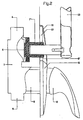
- This adapter is the rest as the adapter (7) arranged and serves the connection of accessories for the shower as the shower bar sections shown (12), a holding arm for soap dishes and so on.
- the water outlet (4) on Mixing and regulating body (1) opened and a water connection for the shower shower be provided outside the shower fitting.
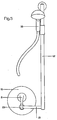
- the accessories (7 ') and (13) for accessories laterally next to the operating lever (2) are arranged.
- the adapter (7 ') or the Adapter (13) by appropriately modified installation of the sanitary fitting arranged below the operating lever (2) and the illustrated Brausestange (12) by means of a crossbar (15) attached to the adapter.
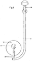
- the adapter (7) for the water supply (9) the shower head (16) below the operating lever (2) arranged and via the connecting pipe (15 ') with the water supply be connected.
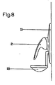
- FIGS. 7 and 8 show attachment possibilities for a soap dish (17; 18) offset laterally next to the control lever (2) or below arranged by this.
- the known Sanitary fittings for installation in the wall of the shower room significantly improved. Maintaining the same fitting and in particular the same control and mixing body as a bathtub fitting with shower hose connection on the one hand and for pure shower baths on the other hand, when used for shower baths the Water connection for the shower head possible directly at the valve and eliminates a separate feed water supply from the valve inside the wall with separate water connection. At the same time the same Cover rosette both when using the sanitary fitting for baths as well as for shower baths. In addition to this technical Advantages is the improved overall aesthetic effect shower baths.
Landscapes
- Health & Medical Sciences (AREA)
- Life Sciences & Earth Sciences (AREA)
- Engineering & Computer Science (AREA)
- Hydrology & Water Resources (AREA)
- Public Health (AREA)
- Water Supply & Treatment (AREA)
- Domestic Plumbing Installations (AREA)
- Bathtubs, Showers, And Their Attachments (AREA)
Abstract
Description
- Fig. 1
- die Sanitärmatur in der Seitenansicht und Längsschnitt im Bereich des Adapters mit eingesetztem Abschnitt des Wasser-Zuleitungsrohrs für die Duschbrause (Misch- und Regelkörper nur als Umriß);
- Fig. 2
- die Sanitärarmatur wie in Fig. 1, jedoch mit eingesetzten Adapter für Accessoires und eingesetztem Abschnitt einer Brausestange;
- Fig. 3
- die Sanitärarmatur wie in Fig. 1 mit einem anderen Adapter für Accessoires und Verschluß der Öffnung des Misch- und Regelkörpers sowie einem Abschnitt der angesetzten Brausestange;
- Fig. 4
- eine Aufsicht auf den Bedienungshebel der Sanitärarmatur und die Abdeckrosette mit Wasserzuführung und Duschbrause gemäß Fig. 1, jedoch mit seitlich neben dem Bedienungshebel angeordneter Wasserzuführung;
- Fig. 5
- eine Aufsicht auf den Bedienungshebel der Sanitärarmatur und die Abdeckrosette mit seitlich angeordneter Brausestange und Traverse zum Adapter gemäß Fig. 2;
- Fig. 6
- eine Aufsicht auf den Bedienungshebel der Sanitärarmatur mit Abdeckrosette mit unterhalb des Bedienhebels angeordneter Wasserzuführung und Duschbrause sowie Verbindungsrohr zum Adapter gemäß Fig. 1;
- Fig. 7
- eine Aufsicht auf den Bedienungshebel der Sanitärarmatur mit Abdeckrosette und seitlich angeordneter, am Adapter gemäß Fig. 2 oder Fig. 3 angebbrachter Seifenschale;
- Fig. 8
- als Seitenansicht den Bedienungshebel der Sanitärarmatur mit Abdeckrosette und unterhalb des Bedienungshebels angeordneter,am Adapter gemäß Fig. 2 oder Fig. 3 angesetzter Seifenschale, ohne Darstellung des Misch- und Regelkörper ssowie des Adapters in der Wand.
Claims (7)
- Sanitärarmatur für Wannen- und/oder Duschbader, vorzugsweise in Form einer Mischbatterie mit Kalt- und Warmwasserzulauf sowie mit Einhebelregelung der Temperatur und Durchflußmenge des Wassers und mit Wasserabgängen zum Badewanneneinlauf einerseits (5) und zur Duschbrause andererseits (4), bei der bei Verwendung für kombinierte Wannen- und Duschbäder in den Misch- und Regelkörper ein Umstellventil mit Zug- und Druckstab für die Zuleitung des Wassers zum Wannen- oder Duschbrauseneinlauf eingesetzt ist, dadurch gekennzeichnet, daß bei Verwendung der Sanitärarmatur allein für Duschbäder statt des Umstellventils mit Zug- und Druckstab in die dafür vorgesehene Öffnung (6) des Misch- und Regelkörpers (1) ein Adapter (7, 7') mittels eines Schraubgewindes oder in anderer Weise eingesetzt ist, wobei der Adapter (7) röhrenförmig sowie zum Misch- und Regelkörper (1) offen ist und zur Wasseranbindung für die Duschbrause das Zuleitungsrohr (9) in den Adapter (7) eingesetzt ist und die Wasserabgänge (4, 5) verschlossen sind, oder wobei der Adapter (7') die Öffnung (6) des Mischund Regelkörpers (1) verschließt und zur Anbindung von Accessoires wie eine Brausestange (12) oder eine Seifenschale (17, 18) dient und der Wasserabgang (4) zur Badewanne verschlossen ist
- Sanitärarmtaur nach Anspruch 1, dadurch gekennzeichnet, daß die Adapter (7, 7') durch die, für den Zug- und Druckstab des Umstellventils vorhandene Bohrung in der Montageplatte (10) auf der Oberfläche der Wand des Duschraums hindurchgeführt ist.
- Sanitärarmatur nach Anspruch 1, dadurch gekennzeichnet, daß in die Öffnung (6) des Misch- und Regelkörpers (1) ein Blindflansch oder sonstiger bekannter Verschluß eingesetzt wird und ein gesonderter Adapter (13) mit einem nasenförmigen Vorsprung (14) in die vorhandene Bohrung der Montageplatte (10) eingesetzt und auf dieser montiert wird und daß am Adapter (13) Accessoires wie die Brausestange (12) oder Seifenschalen (17, 18) angebracht sind.
- Sanitärarmatur gemäß Anspruch 1 oder 3, dadurch gekennzeichnet, daß der Adapter (7, 7', 13) durch entsprechenden Einbau der Sanitärarmatur oberhalb, unterhalb oder seitlich neben dem Bedienungshebel (2) angeordnet ist.
- Sanitärarmatur gemäß Anspruch 4, dadurch gekennzeichnet, daß die Wasserzuführung (9) der Duschbrause (16) mittels des Verbindungsrohrs (15') mit dem Adapter (7) verbunden ist.
- Sanitärarmatur gemäß Anspruch 4, dadurch gekennzeichnet, daß das Accessoire wie die Brausestange (12) mittels einer Traverse (15) am Adapter (7', 13) angesetzt ist.
- Sanitärarmatur gemäß Anspruch 1 oder einem oder mehreren der Ansprüche 2 bis 6, dadurch gekennzeichnet, daß die Sanitärarmatur nicht in der Wand (unter Putz) eingesetzt, sondern auf der Wand (auf Putz) angeordnet ist.
Applications Claiming Priority (2)
| Application Number | Priority Date | Filing Date | Title |
|---|---|---|---|
| DE20300542U DE20300542U1 (de) | 2003-01-14 | 2003-01-14 | Sanitärarmatur zum Unterputzeinbau für Wannen- und/oder Duschbäder |
| DE20300542U | 2003-01-14 |
Publications (3)
| Publication Number | Publication Date |
|---|---|
| EP1441079A2 true EP1441079A2 (de) | 2004-07-28 |
| EP1441079A3 EP1441079A3 (de) | 2004-12-22 |
| EP1441079B1 EP1441079B1 (de) | 2012-03-07 |
Family
ID=7979081
Family Applications (1)
| Application Number | Title | Priority Date | Filing Date |
|---|---|---|---|
| EP04000333A Expired - Lifetime EP1441079B1 (de) | 2003-01-14 | 2004-01-09 | Sanitärarmatur zum Unterputzeinbau für Wannen-und/oder Duschbäder |
Country Status (4)
| Country | Link |
|---|---|
| EP (1) | EP1441079B1 (de) |
| AT (1) | ATE548517T1 (de) |
| DE (1) | DE20300542U1 (de) |
| ES (1) | ES2383680T3 (de) |
Families Citing this family (2)
| Publication number | Priority date | Publication date | Assignee | Title |
|---|---|---|---|---|
| ES1213724Y (es) * | 2018-05-07 | 2018-09-12 | Alba Ivan Alonso | Dispositivo adaptador para duchas |
| CN114607808B (zh) * | 2022-03-23 | 2023-09-01 | 九牧厨卫股份有限公司 | 一种淋浴器 |
Citations (1)
| Publication number | Priority date | Publication date | Assignee | Title |
|---|---|---|---|---|
| DE4040667A1 (de) | 1990-12-19 | 1992-07-02 | Grohe Armaturen Friedrich | Wasserumschaltventil |
Family Cites Families (1)
| Publication number | Priority date | Publication date | Assignee | Title |
|---|---|---|---|---|
| GB9920706D0 (en) * | 1999-09-03 | 1999-11-03 | Newteam Ltd | Shower control valve outlet arrangement |
-
2003
- 2003-01-14 DE DE20300542U patent/DE20300542U1/de not_active Expired - Lifetime
-
2004
- 2004-01-09 EP EP04000333A patent/EP1441079B1/de not_active Expired - Lifetime
- 2004-01-09 AT AT04000333T patent/ATE548517T1/de active
- 2004-01-09 ES ES04000333T patent/ES2383680T3/es not_active Expired - Lifetime
Patent Citations (1)
| Publication number | Priority date | Publication date | Assignee | Title |
|---|---|---|---|---|
| DE4040667A1 (de) | 1990-12-19 | 1992-07-02 | Grohe Armaturen Friedrich | Wasserumschaltventil |
Also Published As
| Publication number | Publication date |
|---|---|
| DE20300542U1 (de) | 2003-06-18 |
| EP1441079B1 (de) | 2012-03-07 |
| ES2383680T3 (es) | 2012-06-25 |
| ATE548517T1 (de) | 2012-03-15 |
| EP1441079A3 (de) | 2004-12-22 |
Similar Documents
| Publication | Publication Date | Title |
|---|---|---|
| EP2053168B1 (de) | Wandeinbau-Ablaufgarnitur für einen sanitären Ablauf | |
| EP1853769A1 (de) | Brauseeinrichtung | |
| DE2456925A1 (de) | Mischbatterie | |
| DE102006033352A1 (de) | Sanitäre Unterputzarmatur mit einem Basiskörper | |
| EP1441079A2 (de) | Sanitärarmatur zum Unterputzeinbau für Wannen-und/oder Duschbäder | |
| DE2516752A1 (de) | Wasserhahnarmatur fuer waschgelegenheiten | |
| EP2495371B1 (de) | Ablaufgarnitur mit einem Wasserzulaufkanal für einen Bodenzulauf | |
| DE3022706A1 (de) | Einloch-mischarmatur, insbesondere fuer den kuechenbereich | |
| DE4108458A1 (de) | Sanitaerarmatur | |
| DE10107913B4 (de) | Brausesystem für den Sanitärbereich | |
| DE3634738C1 (en) | Device for mounting a hand shower attachment on the side of a bath | |
| EP2172595B1 (de) | Wasserarmatur | |
| DE102008055713B4 (de) | Einhandmischer zur Aufbau-Montage | |
| DE9304056U1 (de) | Einhebelmischbatterie | |
| DE7440071U (de) | Mischbatterie | |
| DE19639654C2 (de) | Wandanschlußvorrichtung für Badewannenarmaturgruppen | |
| EP0855635B1 (de) | Sanitärarmatur | |
| DE10317068B3 (de) | Vorrichtung für die sanitäre Wasserinstallation | |
| EP1508291A2 (de) | Vorrichtung bestehend aus einer Sanitärarmatur und einer Befestigungsvorrichtung für ein Accessoireteil | |
| DE2712602A1 (de) | Mischarmatur fuer reihenwaschanlagen | |
| DE10220847A1 (de) | Armatur für Wasser, ausgebildet als Unterdusche zur Körperpflege | |
| DE2042818A1 (de) | ||
| DE4445321A1 (de) | Sanitärarmatur mit auswechselbarem Wasserauslauf | |
| EP1441078A2 (de) | Anordnung eines Brauseschlauchaufrollers in einem Hartschaum-Badewannenträger | |
| DE29700945U1 (de) | Wasserauslaufarmatur mit integriertem Waschmittelspender |
Legal Events
| Date | Code | Title | Description |
|---|---|---|---|
| PUAI | Public reference made under article 153(3) epc to a published international application that has entered the european phase |
Free format text: ORIGINAL CODE: 0009012 |
|
| AK | Designated contracting states |
Kind code of ref document: A2 Designated state(s): AT BE BG CH CY CZ DE DK EE ES FI FR GB GR HU IE IT LI LU MC NL PT RO SE SI SK TR |
|
| AX | Request for extension of the european patent |
Extension state: AL LT LV MK |
|
| RIN1 | Information on inventor provided before grant (corrected) |
Inventor name: FIEGL, TOMAS Inventor name: POHL, ACHIM |
|
| PUAL | Search report despatched |
Free format text: ORIGINAL CODE: 0009013 |
|
| AK | Designated contracting states |
Kind code of ref document: A3 Designated state(s): AT BE BG CH CY CZ DE DK EE ES FI FR GB GR HU IE IT LI LU MC NL PT RO SE SI SK TR |
|
| AX | Request for extension of the european patent |
Extension state: AL LT LV MK |
|
| 17P | Request for examination filed |
Effective date: 20050614 |
|
| AKX | Designation fees paid |
Designated state(s): AT BE BG CH CY CZ DE DK EE ES FI FR GB GR HU IE IT LI LU MC NL PT RO SE SI SK TR |
|
| 17Q | First examination report despatched |
Effective date: 20100819 |
|
| GRAP | Despatch of communication of intention to grant a patent |
Free format text: ORIGINAL CODE: EPIDOSNIGR1 |
|
| GRAS | Grant fee paid |
Free format text: ORIGINAL CODE: EPIDOSNIGR3 |
|
| GRAA | (expected) grant |
Free format text: ORIGINAL CODE: 0009210 |
|
| AK | Designated contracting states |
Kind code of ref document: B1 Designated state(s): AT BE BG CH CY CZ DE DK EE ES FI FR GB GR HU IE IT LI LU MC NL PT RO SE SI SK TR |
|
| REG | Reference to a national code |
Ref country code: GB Ref legal event code: FG4D Free format text: NOT ENGLISH |
|
| REG | Reference to a national code |
Ref country code: DE Ref legal event code: R081 Ref document number: 502004013346 Country of ref document: DE Owner name: IDEAL STANDARD INTERNATIONAL NV, BE Free format text: FORMER OWNER: IDEAL-STANDARD GMBH & CO. OHG, 54516 WITTLICH, DE |
|
| REG | Reference to a national code |
Ref country code: AT Ref legal event code: REF Ref document number: 548517 Country of ref document: AT Kind code of ref document: T Effective date: 20120315 Ref country code: CH Ref legal event code: EP |
|
| REG | Reference to a national code |
Ref country code: IE Ref legal event code: FG4D Free format text: LANGUAGE OF EP DOCUMENT: GERMAN |
|
| REG | Reference to a national code |
Ref country code: DE Ref legal event code: R081 Ref document number: 502004013346 Country of ref document: DE Owner name: IDEAL STANDARD INTERNATIONAL NV, BE Free format text: FORMER OWNER: IDEAL-STANDARD GMBH & CO. OHG, 54516 WITTLICH, DE |
|
| RAP2 | Party data changed (patent owner data changed or rights of a patent transferred) |
Owner name: IDEAL STANDARD INTERNATIONAL BVBA |
|
| REG | Reference to a national code |
Ref country code: DE Ref legal event code: R096 Ref document number: 502004013346 Country of ref document: DE Effective date: 20120503 |
|
| REG | Reference to a national code |
Ref country code: ES Ref legal event code: FG2A Ref document number: 2383680 Country of ref document: ES Kind code of ref document: T3 Effective date: 20120625 |
|
| REG | Reference to a national code |
Ref country code: NL Ref legal event code: VDEP Effective date: 20120307 |
|
| PG25 | Lapsed in a contracting state [announced via postgrant information from national office to epo] |
Ref country code: NL Free format text: LAPSE BECAUSE OF FAILURE TO SUBMIT A TRANSLATION OF THE DESCRIPTION OR TO PAY THE FEE WITHIN THE PRESCRIBED TIME-LIMIT Effective date: 20120307 |
|
| PG25 | Lapsed in a contracting state [announced via postgrant information from national office to epo] |
Ref country code: FI Free format text: LAPSE BECAUSE OF FAILURE TO SUBMIT A TRANSLATION OF THE DESCRIPTION OR TO PAY THE FEE WITHIN THE PRESCRIBED TIME-LIMIT Effective date: 20120307 Ref country code: GR Free format text: LAPSE BECAUSE OF FAILURE TO SUBMIT A TRANSLATION OF THE DESCRIPTION OR TO PAY THE FEE WITHIN THE PRESCRIBED TIME-LIMIT Effective date: 20120608 |
|
| PG25 | Lapsed in a contracting state [announced via postgrant information from national office to epo] |
Ref country code: CY Free format text: LAPSE BECAUSE OF FAILURE TO SUBMIT A TRANSLATION OF THE DESCRIPTION OR TO PAY THE FEE WITHIN THE PRESCRIBED TIME-LIMIT Effective date: 20120307 |
|
| PG25 | Lapsed in a contracting state [announced via postgrant information from national office to epo] |
Ref country code: RO Free format text: LAPSE BECAUSE OF FAILURE TO SUBMIT A TRANSLATION OF THE DESCRIPTION OR TO PAY THE FEE WITHIN THE PRESCRIBED TIME-LIMIT Effective date: 20120307 Ref country code: CZ Free format text: LAPSE BECAUSE OF FAILURE TO SUBMIT A TRANSLATION OF THE DESCRIPTION OR TO PAY THE FEE WITHIN THE PRESCRIBED TIME-LIMIT Effective date: 20120307 Ref country code: SI Free format text: LAPSE BECAUSE OF FAILURE TO SUBMIT A TRANSLATION OF THE DESCRIPTION OR TO PAY THE FEE WITHIN THE PRESCRIBED TIME-LIMIT Effective date: 20120307 Ref country code: SE Free format text: LAPSE BECAUSE OF FAILURE TO SUBMIT A TRANSLATION OF THE DESCRIPTION OR TO PAY THE FEE WITHIN THE PRESCRIBED TIME-LIMIT Effective date: 20120307 Ref country code: EE Free format text: LAPSE BECAUSE OF FAILURE TO SUBMIT A TRANSLATION OF THE DESCRIPTION OR TO PAY THE FEE WITHIN THE PRESCRIBED TIME-LIMIT Effective date: 20120307 |
|
| PG25 | Lapsed in a contracting state [announced via postgrant information from national office to epo] |
Ref country code: PT Free format text: LAPSE BECAUSE OF FAILURE TO SUBMIT A TRANSLATION OF THE DESCRIPTION OR TO PAY THE FEE WITHIN THE PRESCRIBED TIME-LIMIT Effective date: 20120709 Ref country code: SK Free format text: LAPSE BECAUSE OF FAILURE TO SUBMIT A TRANSLATION OF THE DESCRIPTION OR TO PAY THE FEE WITHIN THE PRESCRIBED TIME-LIMIT Effective date: 20120307 |
|
| PLBE | No opposition filed within time limit |
Free format text: ORIGINAL CODE: 0009261 |
|
| STAA | Information on the status of an ep patent application or granted ep patent |
Free format text: STATUS: NO OPPOSITION FILED WITHIN TIME LIMIT |
|
| PG25 | Lapsed in a contracting state [announced via postgrant information from national office to epo] |
Ref country code: DK Free format text: LAPSE BECAUSE OF FAILURE TO SUBMIT A TRANSLATION OF THE DESCRIPTION OR TO PAY THE FEE WITHIN THE PRESCRIBED TIME-LIMIT Effective date: 20120307 |
|
| 26N | No opposition filed |
Effective date: 20121210 |
|
| REG | Reference to a national code |
Ref country code: DE Ref legal event code: R097 Ref document number: 502004013346 Country of ref document: DE Effective date: 20121210 |
|
| BERE | Be: lapsed |
Owner name: IDEAL-STANDARD G.M.B.H. & CO. OHG Effective date: 20130131 |
|
| PG25 | Lapsed in a contracting state [announced via postgrant information from national office to epo] |
Ref country code: BG Free format text: LAPSE BECAUSE OF FAILURE TO SUBMIT A TRANSLATION OF THE DESCRIPTION OR TO PAY THE FEE WITHIN THE PRESCRIBED TIME-LIMIT Effective date: 20120607 |
|
| PG25 | Lapsed in a contracting state [announced via postgrant information from national office to epo] |
Ref country code: MC Free format text: LAPSE BECAUSE OF NON-PAYMENT OF DUE FEES Effective date: 20130131 |
|
| REG | Reference to a national code |
Ref country code: CH Ref legal event code: PL |
|
| REG | Reference to a national code |
Ref country code: IE Ref legal event code: MM4A |
|
| PG25 | Lapsed in a contracting state [announced via postgrant information from national office to epo] |
Ref country code: CH Free format text: LAPSE BECAUSE OF NON-PAYMENT OF DUE FEES Effective date: 20130131 Ref country code: LI Free format text: LAPSE BECAUSE OF NON-PAYMENT OF DUE FEES Effective date: 20130131 Ref country code: BE Free format text: LAPSE BECAUSE OF NON-PAYMENT OF DUE FEES Effective date: 20130131 |
|
| PG25 | Lapsed in a contracting state [announced via postgrant information from national office to epo] |
Ref country code: IE Free format text: LAPSE BECAUSE OF NON-PAYMENT OF DUE FEES Effective date: 20130109 |
|
| PG25 | Lapsed in a contracting state [announced via postgrant information from national office to epo] |
Ref country code: HU Free format text: LAPSE BECAUSE OF FAILURE TO SUBMIT A TRANSLATION OF THE DESCRIPTION OR TO PAY THE FEE WITHIN THE PRESCRIBED TIME-LIMIT; INVALID AB INITIO Effective date: 20040109 Ref country code: LU Free format text: LAPSE BECAUSE OF NON-PAYMENT OF DUE FEES Effective date: 20130109 |
|
| REG | Reference to a national code |
Ref country code: FR Ref legal event code: PLFP Year of fee payment: 13 |
|
| REG | Reference to a national code |
Ref country code: DE Ref legal event code: R081 Ref document number: 502004013346 Country of ref document: DE Owner name: IDEAL STANDARD INTERNATIONAL NV, BE Free format text: FORMER OWNER: IDEAL-STANDARD INTERNATIONAL BVBA, BRUESSEL, BE Ref country code: DE Ref legal event code: R082 Ref document number: 502004013346 Country of ref document: DE Representative=s name: PATENTANWAELTE BECKER & MUELLER, DE |
|
| REG | Reference to a national code |
Ref country code: FR Ref legal event code: PLFP Year of fee payment: 14 |
|
| REG | Reference to a national code |
Ref country code: FR Ref legal event code: PLFP Year of fee payment: 15 |
|
| PGFP | Annual fee paid to national office [announced via postgrant information from national office to epo] |
Ref country code: AT Payment date: 20211221 Year of fee payment: 19 |
|
| PGFP | Annual fee paid to national office [announced via postgrant information from national office to epo] |
Ref country code: FR Payment date: 20230125 Year of fee payment: 20 Ref country code: ES Payment date: 20230201 Year of fee payment: 20 |
|
| PGFP | Annual fee paid to national office [announced via postgrant information from national office to epo] |
Ref country code: TR Payment date: 20230109 Year of fee payment: 20 Ref country code: IT Payment date: 20230120 Year of fee payment: 20 Ref country code: GB Payment date: 20230127 Year of fee payment: 20 Ref country code: DE Payment date: 20230127 Year of fee payment: 20 |
|
| REG | Reference to a national code |
Ref country code: AT Ref legal event code: MM01 Ref document number: 548517 Country of ref document: AT Kind code of ref document: T Effective date: 20230109 |
|
| PG25 | Lapsed in a contracting state [announced via postgrant information from national office to epo] |
Ref country code: AT Free format text: LAPSE BECAUSE OF NON-PAYMENT OF DUE FEES Effective date: 20230109 |
|
| REG | Reference to a national code |
Ref country code: DE Ref legal event code: R071 Ref document number: 502004013346 Country of ref document: DE |
|
| REG | Reference to a national code |
Ref country code: ES Ref legal event code: FD2A Effective date: 20240126 |
|
| REG | Reference to a national code |
Ref country code: GB Ref legal event code: PE20 Expiry date: 20240108 |
|
| PG25 | Lapsed in a contracting state [announced via postgrant information from national office to epo] |
Ref country code: ES Free format text: LAPSE BECAUSE OF EXPIRATION OF PROTECTION Effective date: 20240110 |
|
| PG25 | Lapsed in a contracting state [announced via postgrant information from national office to epo] |
Ref country code: ES Free format text: LAPSE BECAUSE OF EXPIRATION OF PROTECTION Effective date: 20240110 Ref country code: GB Free format text: LAPSE BECAUSE OF EXPIRATION OF PROTECTION Effective date: 20240108 |