EP1441185A2 - Appareil frigorifique - Google Patents
Appareil frigorifique Download PDFInfo
- Publication number
- EP1441185A2 EP1441185A2 EP04000745A EP04000745A EP1441185A2 EP 1441185 A2 EP1441185 A2 EP 1441185A2 EP 04000745 A EP04000745 A EP 04000745A EP 04000745 A EP04000745 A EP 04000745A EP 1441185 A2 EP1441185 A2 EP 1441185A2
- Authority
- EP
- European Patent Office
- Prior art keywords
- refrigerant
- compressor
- heat exchanger
- pipe
- throttle apparatus
- Prior art date
- Legal status (The legal status is an assumption and is not a legal conclusion. Google has not performed a legal analysis and makes no representation as to the accuracy of the status listed.)
- Withdrawn
Links
Images


Classifications
-
- A—HUMAN NECESSITIES
- A61—MEDICAL OR VETERINARY SCIENCE; HYGIENE
- A61D—VETERINARY INSTRUMENTS, IMPLEMENTS, TOOLS, OR METHODS
- A61D7/00—Devices or methods for introducing solid, liquid, or gaseous remedies or other materials into or onto the bodies of animals
-
- F—MECHANICAL ENGINEERING; LIGHTING; HEATING; WEAPONS; BLASTING
- F25—REFRIGERATION OR COOLING; COMBINED HEATING AND REFRIGERATION SYSTEMS; HEAT PUMP SYSTEMS; MANUFACTURE OR STORAGE OF ICE; LIQUEFACTION SOLIDIFICATION OF GASES
- F25B—REFRIGERATION MACHINES, PLANTS OR SYSTEMS; COMBINED HEATING AND REFRIGERATION SYSTEMS; HEAT PUMP SYSTEMS
- F25B13/00—Compression machines, plants or systems, with reversible cycle
-
- F—MECHANICAL ENGINEERING; LIGHTING; HEATING; WEAPONS; BLASTING
- F25—REFRIGERATION OR COOLING; COMBINED HEATING AND REFRIGERATION SYSTEMS; HEAT PUMP SYSTEMS; MANUFACTURE OR STORAGE OF ICE; LIQUEFACTION SOLIDIFICATION OF GASES
- F25B—REFRIGERATION MACHINES, PLANTS OR SYSTEMS; COMBINED HEATING AND REFRIGERATION SYSTEMS; HEAT PUMP SYSTEMS
- F25B9/00—Compression machines, plants or systems, in which the refrigerant is air or other gas of low boiling point
- F25B9/002—Compression machines, plants or systems, in which the refrigerant is air or other gas of low boiling point characterised by the refrigerant
- F25B9/008—Compression machines, plants or systems, in which the refrigerant is air or other gas of low boiling point characterised by the refrigerant the refrigerant being carbon dioxide
-
- F—MECHANICAL ENGINEERING; LIGHTING; HEATING; WEAPONS; BLASTING
- F25—REFRIGERATION OR COOLING; COMBINED HEATING AND REFRIGERATION SYSTEMS; HEAT PUMP SYSTEMS; MANUFACTURE OR STORAGE OF ICE; LIQUEFACTION SOLIDIFICATION OF GASES
- F25B—REFRIGERATION MACHINES, PLANTS OR SYSTEMS; COMBINED HEATING AND REFRIGERATION SYSTEMS; HEAT PUMP SYSTEMS
- F25B2309/00—Gas cycle refrigeration machines
- F25B2309/06—Compression machines, plants or systems characterised by the refrigerant being carbon dioxide
- F25B2309/061—Compression machines, plants or systems characterised by the refrigerant being carbon dioxide with cycle highest pressure above the supercritical pressure
-
- F—MECHANICAL ENGINEERING; LIGHTING; HEATING; WEAPONS; BLASTING
- F25—REFRIGERATION OR COOLING; COMBINED HEATING AND REFRIGERATION SYSTEMS; HEAT PUMP SYSTEMS; MANUFACTURE OR STORAGE OF ICE; LIQUEFACTION SOLIDIFICATION OF GASES
- F25B—REFRIGERATION MACHINES, PLANTS OR SYSTEMS; COMBINED HEATING AND REFRIGERATION SYSTEMS; HEAT PUMP SYSTEMS
- F25B2400/00—Component parts or details not otherwise provided for in this subclass
- F25B2400/13—Economisers
-
- F—MECHANICAL ENGINEERING; LIGHTING; HEATING; WEAPONS; BLASTING
- F25—REFRIGERATION OR COOLING; COMBINED HEATING AND REFRIGERATION SYSTEMS; HEAT PUMP SYSTEMS; MANUFACTURE OR STORAGE OF ICE; LIQUEFACTION SOLIDIFICATION OF GASES
- F25B—REFRIGERATION MACHINES, PLANTS OR SYSTEMS; COMBINED HEATING AND REFRIGERATION SYSTEMS; HEAT PUMP SYSTEMS
- F25B2400/00—Component parts or details not otherwise provided for in this subclass
- F25B2400/23—Separators
-
- F—MECHANICAL ENGINEERING; LIGHTING; HEATING; WEAPONS; BLASTING
- F25—REFRIGERATION OR COOLING; COMBINED HEATING AND REFRIGERATION SYSTEMS; HEAT PUMP SYSTEMS; MANUFACTURE OR STORAGE OF ICE; LIQUEFACTION SOLIDIFICATION OF GASES
- F25B—REFRIGERATION MACHINES, PLANTS OR SYSTEMS; COMBINED HEATING AND REFRIGERATION SYSTEMS; HEAT PUMP SYSTEMS
- F25B2600/00—Control issues
- F25B2600/25—Control of valves
- F25B2600/2509—Economiser valves
-
- F—MECHANICAL ENGINEERING; LIGHTING; HEATING; WEAPONS; BLASTING
- F25—REFRIGERATION OR COOLING; COMBINED HEATING AND REFRIGERATION SYSTEMS; HEAT PUMP SYSTEMS; MANUFACTURE OR STORAGE OF ICE; LIQUEFACTION SOLIDIFICATION OF GASES
- F25B—REFRIGERATION MACHINES, PLANTS OR SYSTEMS; COMBINED HEATING AND REFRIGERATION SYSTEMS; HEAT PUMP SYSTEMS
- F25B2700/00—Sensing or detecting of parameters; Sensors therefor
- F25B2700/19—Pressures
- F25B2700/193—Pressures of the compressor
- F25B2700/1931—Discharge pressures
-
- F—MECHANICAL ENGINEERING; LIGHTING; HEATING; WEAPONS; BLASTING
- F25—REFRIGERATION OR COOLING; COMBINED HEATING AND REFRIGERATION SYSTEMS; HEAT PUMP SYSTEMS; MANUFACTURE OR STORAGE OF ICE; LIQUEFACTION SOLIDIFICATION OF GASES
- F25B—REFRIGERATION MACHINES, PLANTS OR SYSTEMS; COMBINED HEATING AND REFRIGERATION SYSTEMS; HEAT PUMP SYSTEMS
- F25B2700/00—Sensing or detecting of parameters; Sensors therefor
- F25B2700/19—Pressures
- F25B2700/193—Pressures of the compressor
- F25B2700/1933—Suction pressures
-
- F—MECHANICAL ENGINEERING; LIGHTING; HEATING; WEAPONS; BLASTING
- F25—REFRIGERATION OR COOLING; COMBINED HEATING AND REFRIGERATION SYSTEMS; HEAT PUMP SYSTEMS; MANUFACTURE OR STORAGE OF ICE; LIQUEFACTION SOLIDIFICATION OF GASES
- F25B—REFRIGERATION MACHINES, PLANTS OR SYSTEMS; COMBINED HEATING AND REFRIGERATION SYSTEMS; HEAT PUMP SYSTEMS
- F25B2700/00—Sensing or detecting of parameters; Sensors therefor
- F25B2700/21—Temperatures
- F25B2700/2115—Temperatures of a compressor or the drive means therefor
- F25B2700/21152—Temperatures of a compressor or the drive means therefor at the discharge side of the compressor
-
- F—MECHANICAL ENGINEERING; LIGHTING; HEATING; WEAPONS; BLASTING
- F25—REFRIGERATION OR COOLING; COMBINED HEATING AND REFRIGERATION SYSTEMS; HEAT PUMP SYSTEMS; MANUFACTURE OR STORAGE OF ICE; LIQUEFACTION SOLIDIFICATION OF GASES
- F25B—REFRIGERATION MACHINES, PLANTS OR SYSTEMS; COMBINED HEATING AND REFRIGERATION SYSTEMS; HEAT PUMP SYSTEMS
- F25B31/00—Compressor arrangements
- F25B31/006—Cooling of compressor or motor
Definitions
- the present invention relates a refrigerator used in an air conditioner or the like.
- Fig. 4 shows a conventional refrigerator (see Patent Document 1 for example).
- a reference number 1 represents a compressor
- a reference number 2 represents an outdoor heat exchanger
- a reference number 3 represents an indoor heat exchanger
- a reference number 4 represents an accumulator
- a reference number 5 represents a four-way valve.
- the outdoor heat exchanger 2 and the indoor heat exchanger 3 are connected to each other through a refrigerant passage 17.
- a refrigerant passage 17 is provided with the first expansion valve 11, the second expansion valve 12 and a third expansion valve 13 in series.
- the refrigerant passage 17 between the first expansion valve 11 and the second expansion valve 12 is provided with a receiver 7 for separating gas and liquid from each other.
- An inner heat exchanger 8 includes a high pressure-side heat transfer section 8a and a low pressure-side heat transfer section 8b.
- the refrigerant passage 17 between a second expansion valve 12 and a third expansion valve 13 is provided with the high pressure-side heat transfer section 8a of the inner heat exchanger 8.
- One end of the low pressure-side heat transfer section 8b of the inner heat exchanger 8 is connected to a refrigerant passage 14 and the other end of the low pressure-side heat transfer section 8b is connected to a refrigerant passage 15.
- the refrigerant passage 14 is an outlet-side pipe of the four-way valve 5, and the refrigerant passage 15 is an inlet-side pipe to the accumulator 4.
- a gas phase section of the receiver 7 is connected to a compressing chamber of the compressor 1 through a refrigerant passage 16 including a control valve 10.
- This conventional refrigerator uses carbon dioxide as a refrigerant.
- FIG. 5 is a diagram showing "P(pressure) - h(enthalpy)".
- CO2 refrigerant (gas refrigerant) discharged from the compressor 1 is introduced into the outdoor heat exchanger 2 through the four-way valve 5, and heat of the refrigerant is dissipated at a supercritical region (regions of points D to E in Fig. 5) in the outdoor heat exchanger 2.
- the CO2 refrigerant in a supercritical state flowing out from the outdoor heat exchanger 2 is primarily expanded in the first expansion valve 11 (regions of points E to F), and introduced into the receiver 7 in a gas-liquid two phases, and gas and liquid are separated here (points G and H).
- a liquid refrigerant separated in the receiver 7 passes through the fully-opened second expansion valve 12 and flows into the high pressure-side heat transfer section 8a of the inner heat exchanger 8. While the liquid refrigerant flows from an inlet (point H) of the high pressure-side heat transfer section 8a toward an outlet (point I) of the high pressure-side heat transfer section 8a, the liquid refrigerant exchanges heat between itself and gas refrigerant which flows from an inlet (point K) of the low pressure-side heat transfer section 8b toward an outlet (point A) of the lowpressure-side heat transfer section 8b. Then, the liquid refrigerant is secondarily expanded in the third expansion valve 13 (regions of points I to J).
- the liquid refrigerant is sent to the indoor heat exchanger 3 and is evaporated while it flows from an inlet (point J) of the indoor heat exchanger 3 to an outlet (point K) of the indoor heat exchanger 3 and becomes gas refrigerant.
- This gas refrigerant is again drawn into the compressor 1 and compressed.
- the drawing temperature is higher (i.e., temperature corresponding to point A) than the outlet temperature (temperature corresponding to point K) of the indoor heat exchanger 3 by a temperature (shown with "d") increased by the internal heat exchange in the inner heat exchanger 8.
- the gas refrigerant separated by the receiver 7 is injected into the compressing chamber which is in a compression stroke of the compressor 1 through the refrigerant passage 16 (see point G).
- the gas refrigerant is injected into the compressing chamber of the compressor 1 in this manner, and the gas refrigerant is mixed with a gas refrigerant in the compressing chamber, thereby facilitating the cooling effect and high density effect of the gas refrigerant in the compressing chamber. Therefore, the drawing temperature of the compressor 1 is increased by the internal heat exchange, and a temperature of the gas refrigerant in the compressing chamber is once reduced to a temperature corresponding to point C from a temperature corresponding to point B at the time of gas injection irrespective of a fact that the compression is started from this high drawing temperature, and the reduced temperature is again increased and the temperature corresponding to point D becomes a discharging temperature.
- the discharging temperature is affected by temperature reduction associated with the gas injection, and the discharging temperature can be lower than a temperature (temperature corresponding to point D0 ) when the gas injection is not carried out and the refrigerant is compressed from point A to point D0, and the reliability of the compressor 1 can be enhanced.
- the present invention has been accomplished to solve the conventional problem, and it is an object of the invention to provide a refrigerator in which even if carbon dioxide is used as a refrigerant and the refrigerator is operated at high compression ratio, a discharging temperature of the compressor can reliably and safely be reduced.
- the refrigerator of the invention comprises an injection pipe for injecting a refrigerant in a supercritical state of a radiator outlet into a cylinder of a compressor. Since the refrigerant in the supercritical state having low enthalpy which is discharged from the radiator is directly injected into the compressor, even if the amount of refrigerant is small, the effect for reducing a discharging temperature of the compressor is great. Further, not a liquid refrigerant but the refrigerant in the supercritical state is injected and thus, liquid compression is not carried out and the reliability is enhanced.
- the refrigerant in the supercritical state of an outlet of an outdoor heat exchanger or an outlet of an indoor heat exchanger is injected into the cylinder of the compressor using a check valve, the refrigerant in the supercritical state having the low enthalpy can directly be injected to the compressor, the discharging temperature of the compressor can largely be reduced. Since the refrigerant is in the supercritical state, liquid compression is not carried out and the reliability is enhanced.
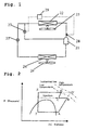
- Fig. 1 is a block diagram of a refrigerator according to an embodiment 1 of the present invention.
- a reference number 21 represents a compressor
- a reference number 22 represents a radiator
- a reference number 23 represents a first throttle apparatus
- a reference number 24 represents an evaporator
- a reference number 25 represents a fan for the radiator 22
- a reference number 26 represents a fan for the evaporator 24.
- a pipe which is branched off from a pipe on the side of an outlet of the radiator 22 is connected to a cylinder (not shown) of the compressor 21, and a second throttle apparatus 27 is provided in an intermediate portion of the branched pipe, and a refrigerant on the side of the outlet of the radiator 22 is injected into the cylinder of the compressor 21.
- a temperature sensor 28 detects a discharged gas temperature of the compressor 21.
- a control apparatus 29 compares the discharged gas temperature and a set value and controls an opening degree of the second throttle apparatus 27.
- the refrigerator uses carbon dioxide as the refrigerant.
- Fig. 2 is a "P (pressure) -h (enthalpy) diagram".
- a refrigerant (carbon dioxide) is compressed to a high pressure and discharged by the compressor 21.
- the discharged refrigerant is introduced into the radiator 22, heat thereof is exchanged with air by the fan 25, and the heat is dissipated in a supercritical region (region of points D to E in Fig. 2).
- the carbon dioxide refrigerant in the supercritical state flowing out from the radiator 22 is expanded by the first throttle apparatus 23 (regions of points E and F).
- the carbon dioxide refrigerant is heat-exchanged with air by the fan 26 and is evaporated and becomes a gas refrigerant (regions of points F to A).
- the gas refrigerant is again drawn into the compressor 21 (point A) and compressed.
- the control apparatus 29 outputs a command for increasing an opening degree of the second throttle apparatus 27 so that refrigerant flows.
- the drawn gas compressed in the cylinder (point A) is compressed up to point B where the drawn gas is mixed with the injected refrigerant, a temperature thereof is reduced to the state of point C, and the drawn gas is further compressed and brought into a high pressure state (point D).
- the state of point D can largely be reduced in temperature as compared with a discharged gas temperature when the refrigerant is not injected (point D'), and it is possible to prevent the reliability of the compressor 21 from being deteriorated due to temperature rise.
- the injected refrigerant in the supercritical state is not a liquid refrigerant, it has compressibility. That is, if a liquid refrigerant having a temperature of 20°C and a pressure of 6MPa is adiabatic-compressed and its pressure becomes 30MPa in supercritical state, its density is increased only by about 10% and it is not compressed almost at all. However, if a carbon dioxide refrigerant in the supercritical state having a temperature of 35°C and a pressure of 8MPa is adiabatic-compressed to 30MPa, its density is increased by about 60%, and its compressibility is great.
- the opening degree of the second throttle apparatus 27 is controlled in association with a difference between a discharged gas temperature of the compressor 21 detected by the temperature sensor 28 and a temperature which is preset in the control apparatus 29.
- high pressure and low pressure may be detected and the opening degree of the second throttle apparatus 27 may be controlled in association with the pressures.
- Such a method is also one of embodiments of this invention.
- Fig. 3 is a block diagram of a refrigerator in an embodiment 2 of the present invention.
- the refrigerator in the embodiment 2 includes a four-way valve 30 which switches cooling and warming operations, an outdoor heat exchanger 31, a first throttle apparatus 23 and an indoor heat exchanger 32 are connected to one another to constitute a main circuit of the refrigeration cycle.
- a pipe branched off from a pipe between the outdoor heat exchanger 31 and the first throttle apparatus 23 is connected to a cylinder (not shown) of the compressor 21, and a check valve 33 is connected to an intermediate portion of the branched pipe so that a refrigerant only flows toward the compressor 21 (in a direction shown with solid arrows in Fig. 3).
- a pipe branched off from a pipe between the indoor heat exchanger 32 and the first throttle apparatus 23 is connected to the cylinder (not shown) of the compressor 21, and a check valve 34 is connected to an intermediate portion of the branched pipe so that a refrigerant only flows toward the compressor 21 (in a direction shown with broken arrows in Fig. 3).
- the pipe on the side of an outlet of the check valve 33 and the pipe on the side of an outlet of the check valve 34 are merged with each other as a common pipe, and this common pipe is connected to a second throttle apparatus 27.
- a refrigerant between the outdoor heat exchanger 31 and the first throttle apparatus 23 is injected into the cylinder of the compressor 21 at the time of the cooling operation, and a refrigerant between the indoor heat exchanger 32 and the first throttle apparatus 23 is injected into the cylinder of the compressor 21 at the time of warming operation.
- the refrigerator uses carbon dioxide as the refrigerant.
- Fig. 2 is a "P(pressure)-h(enthalpy) diagram".
- a refrigerant (carbon dioxide) which was compressed to a high pressure and discharged by the compressor 21 passes through the four-way valve 30 and flows in the direction shown with solid arrows and is introduced into the outdoor heat exchanger 31.
- Heat of the refrigerant is exchanged with outdoor air sent by the fan 25 and dissipated in the supercritical region (regions of points D to E in Fig. 2).
- the carbon dioxide refrigerant in the supercritical state flowing out from the outdoor heat exchanger 31 is expanded in the first throttle apparatus 23 (regions of points E to F), and heat of the refrigerant is exchanged with indoor air sent by the fan 26 in the indoor heat exchanger 32 to carry out the cooling operation.
- the refrigerant is evaporated and becomes a gas refrigerant (regions of points F to A).
- the gas refrigerant passes through the four-way valve 30 and is again drawn into the compressor 21 (point A) and compressed.
- the control apparatus 29 outputs a command for increasing an opening degree of the second throttle apparatus 27 so that refrigerant flows.
- the drawn gas compressed in the cylinder (point A) is compressed up to point B where the drawn gas is mixed with the injected refrigerant, a temperature thereof is reduced to the state of point C, and the drawn gas is further compressed and brought into a high pressure state (point D).
- the state of point D can largely be reduced in temperature as compared with a discharged gas temperature when the refrigerant is not injected (point D'), and it is possible to prevent the reliability of the compressor 21 from being deteriorated due to temperature rise.
- the injected refrigerant in the supercritical state is not a liquid refrigerant, it has compressibility. For this reason, even if a large amount of refrigerant in the supercritical state is temporarily injected and mixed into the cylinder or bearing, an abnormal pressure rise by capacity reduction of the cylinder or bearing is less prone to be generated, and various sliding parts in the compressor 21 can be prevented from being worn and thus, the reliability is enhanced.
- a refrigerant (carbon dioxide) which was compressed to a high pressure and discharged by the compressor 21 passes through the four-way valve 30 and flows in the direction shown with broken arrows and is introduced into the indoor heat exchanger 32.
- Heat of the refrigerant is exchanged with indoor air sent by the fan 26 to carry out the warming operation and dissipated in the supercritical region (regions of points D to E in Fig. 2).
- the carbon dioxide refrigerant in the supercritical state flowing out from the indoor heat exchanger 32 is expanded in the first throttle apparatus 23 (regions of points E to F), and heat of the refrigerant is exchanged with outdoor air sent by the fan 25 in the outdoor heat exchanger 31.
- the refrigerant is evaporated and becomes a gas refrigerant (regions of points F to A).
- the gas refrigerant passes through the four-way valve 30 and is again drawn into the compressor 21 (point A) and compressed.
- the control apparatus 29 outputs a command for increasing an opening degree of the second throttle apparatus 27 so that refrigerant flows.
- a portion of the refrigerant in the supercritical state flowing out from the indoor heat exchanger 32 passes (point E) through the check valve 34 and the second throttle apparatus 27 and is injected into the cylinder of the compressor 21.
- the discharging pressure when high temperature wind is necessary such as warming operation when outside temperature is low, the discharging pressure is increased, the drawing pressure is reduced and the discharging temperature is abnormally increased. Therefore, the discharging temperature can reliably be reduced by the present invention and various sliding parts in the compressor 21 can be prevented from being worn and thus, the reliability is enhanced.
- the opening degree of the second throttle apparatus 27 is controlled in association with a difference between a discharged gas temperature of the compressor 21 detected by the temperature sensor 28 and a temperature which is preset in the control apparatus 29.
- high pressure and low pressure may be detected and the opening degree of the second throttle apparatus 27 may be controlled in association with the pressures.
- Such a method is also one of embodiments of this invention.
- the refrigerator of the present invention since the refrigerant in the supercritical state is directly injected to the compressor, even if the amount of the refrigerant is small, the effect for reducing the discharging temperature is great, and since the refrigerant in the supercritical state has higher compressibility than that of the liquid refrigerant, even if the refrigerant in the supercritical state is mixed into the cylinder or bearing, the pressure is less prone to be increased abnormally unlike the conventional liquid compression, various sliding parts can be prevented from being worn, and the reliability can be enhanced.
Landscapes
- Engineering & Computer Science (AREA)
- Thermal Sciences (AREA)
- General Engineering & Computer Science (AREA)
- Physics & Mathematics (AREA)
- Mechanical Engineering (AREA)
- Life Sciences & Earth Sciences (AREA)
- Chemical Kinetics & Catalysis (AREA)
- Health & Medical Sciences (AREA)
- Chemical & Material Sciences (AREA)
- Veterinary Medicine (AREA)
- Animal Behavior & Ethology (AREA)
- Zoology (AREA)
- Wood Science & Technology (AREA)
- General Health & Medical Sciences (AREA)
- Public Health (AREA)
- Air-Conditioning For Vehicles (AREA)
- Devices That Are Associated With Refrigeration Equipment (AREA)
- Air Conditioning Control Device (AREA)
- Applications Or Details Of Rotary Compressors (AREA)
Applications Claiming Priority (2)
| Application Number | Priority Date | Filing Date | Title |
|---|---|---|---|
| JP2003007983 | 2003-01-16 | ||
| JP2003007983A JP2004218964A (ja) | 2003-01-16 | 2003-01-16 | 冷凍装置 |
Publications (2)
| Publication Number | Publication Date |
|---|---|
| EP1441185A2 true EP1441185A2 (fr) | 2004-07-28 |
| EP1441185A3 EP1441185A3 (fr) | 2004-10-06 |
Family
ID=32588524
Family Applications (1)
| Application Number | Title | Priority Date | Filing Date |
|---|---|---|---|
| EP04000745A Withdrawn EP1441185A3 (fr) | 2003-01-16 | 2004-01-15 | Appareil frigorifique |
Country Status (5)
| Country | Link |
|---|---|
| US (1) | US7024879B2 (fr) |
| EP (1) | EP1441185A3 (fr) |
| JP (1) | JP2004218964A (fr) |
| KR (1) | KR20040066028A (fr) |
| CN (1) | CN1517635A (fr) |
Cited By (3)
| Publication number | Priority date | Publication date | Assignee | Title |
|---|---|---|---|---|
| EP2527764A3 (fr) * | 2008-03-31 | 2014-06-18 | Mitsubishi Electric Corporation | Appareil extérieur d'alimentation en eau chaude de type pompe à chaleur |
| CN106403349A (zh) * | 2016-11-25 | 2017-02-15 | 广东美的制冷设备有限公司 | 一种双缸变容空调系统及控制方法 |
| US20210197648A1 (en) * | 2018-08-30 | 2021-07-01 | Sanden Holdings Corporation | Heat pump system for vehicle air conditioning devices |
Families Citing this family (19)
| Publication number | Priority date | Publication date | Assignee | Title |
|---|---|---|---|---|
| US20100192607A1 (en) * | 2004-10-14 | 2010-08-05 | Mitsubishi Electric Corporation | Air conditioner/heat pump with injection circuit and automatic control thereof |
| WO2007110908A1 (fr) | 2006-03-27 | 2007-10-04 | Mitsubishi Denki Kabushiki Kaisha | Dispositif de climatisation frigorifique |
| JP4459776B2 (ja) | 2004-10-18 | 2010-04-28 | 三菱電機株式会社 | ヒートポンプ装置及びヒートポンプ装置の室外機 |
| WO2006057141A1 (fr) * | 2004-11-25 | 2006-06-01 | Mitsubishi Denki Kabushiki Kaisha | Climatiseur |
| JP2007040278A (ja) * | 2005-08-05 | 2007-02-15 | Sanden Corp | 圧縮機 |
| JP2009052752A (ja) * | 2005-12-19 | 2009-03-12 | Panasonic Corp | 冷凍サイクル装置 |
| EP2153139A4 (fr) * | 2007-05-23 | 2012-10-10 | Carrier Corp | Injection de réfrigérant au-dessus du point critique dans un système de réfrigérant transcritique |
| JP5242434B2 (ja) * | 2009-01-30 | 2013-07-24 | パナソニック株式会社 | 液体循環式暖房システム |
| JP5502410B2 (ja) * | 2009-01-30 | 2014-05-28 | パナソニック株式会社 | 液体循環式暖房システム |
| JP4550153B2 (ja) * | 2009-07-30 | 2010-09-22 | 三菱電機株式会社 | ヒートポンプ装置及びヒートポンプ装置の室外機 |
| JP4767340B2 (ja) * | 2009-07-30 | 2011-09-07 | 三菱電機株式会社 | ヒートポンプ装置の制御装置 |
| US9599378B2 (en) * | 2011-01-31 | 2017-03-21 | Mitsubishi Electric Corporation | Air-conditioning apparatus |
| AU2011358038B2 (en) * | 2011-01-31 | 2015-01-22 | Mitsubishi Electric Corporation | Air-conditioning apparatus |
| JP5657030B2 (ja) * | 2011-01-31 | 2015-01-21 | 三菱電機株式会社 | 空気調和装置 |
| WO2014054120A1 (fr) * | 2012-10-02 | 2014-04-10 | 三菱電機株式会社 | Appareil de conditionnement d'air |
| EP2924367B1 (fr) * | 2012-11-21 | 2021-11-03 | Mitsubishi Electric Corporation | Dispositif de climatisation |
| EP2924366B1 (fr) * | 2012-11-21 | 2020-06-17 | Mitsubishi Electric Corporation | Dispositif de climatisation |
| WO2017163339A1 (fr) * | 2016-03-23 | 2017-09-28 | 三菱電機株式会社 | Dispositif de climatisation |
| ES2988386T3 (es) * | 2020-04-07 | 2024-11-20 | Mitsubishi Electric Corp | Dispositivo de ciclo de refrigeración |
Citations (1)
| Publication number | Priority date | Publication date | Assignee | Title |
|---|---|---|---|---|
| JP2001296067A (ja) | 2000-04-13 | 2001-10-26 | Daikin Ind Ltd | Co2冷媒を用いた冷凍システム |
Family Cites Families (16)
| Publication number | Priority date | Publication date | Assignee | Title |
|---|---|---|---|---|
| US439326A (en) * | 1890-10-28 | Apparatus for handling hay | ||
| JPS5223402B2 (fr) * | 1973-10-12 | 1977-06-24 | ||
| JPS5585853A (en) * | 1978-12-20 | 1980-06-28 | Tokyo Shibaura Electric Co | Refrigeration cycle |
| JPH01239350A (ja) * | 1988-03-18 | 1989-09-25 | Hitachi Ltd | 冷凍サイクル装置 |
| US4919128A (en) * | 1988-08-26 | 1990-04-24 | University Technologies International Inc. | Nasal adaptor device and seal |
| US5062274A (en) * | 1989-07-03 | 1991-11-05 | Carrier Corporation | Unloading system for two compressors |
| DE4127754C2 (de) * | 1991-08-22 | 1997-01-30 | Bitzer Kuehlmaschinenbau Gmbh | Verdichter mit Zwischenkühlung |
| JPH05288421A (ja) * | 1992-04-03 | 1993-11-02 | Matsushita Seiko Co Ltd | 個別型空気調和機の冷媒制御装置 |
| JPH1163694A (ja) * | 1997-08-21 | 1999-03-05 | Zexel Corp | 冷却サイクル |
| EP1033541B1 (fr) * | 1997-11-17 | 2004-07-21 | Daikin Industries, Limited | Appareil refrigerant |
| JP2001041598A (ja) * | 1999-07-30 | 2001-02-16 | Mitsubishi Heavy Ind Ltd | 多段圧縮冷凍機 |
| JP2001133057A (ja) * | 1999-11-04 | 2001-05-18 | Sanden Corp | 超臨界冷凍サイクル |
| JP2002195677A (ja) * | 2000-10-20 | 2002-07-10 | Denso Corp | ヒートポンプサイクル |
| JP4622193B2 (ja) | 2001-08-31 | 2011-02-02 | ダイキン工業株式会社 | 冷凍装置 |
| JP2003074997A (ja) | 2001-09-04 | 2003-03-12 | Sanyo Electric Co Ltd | 超臨界冷凍装置 |
| JP2003262414A (ja) * | 2002-03-08 | 2003-09-19 | Osaka Gas Co Ltd | 圧縮式ヒートポンプ及び給湯装置 |
-
2003
- 2003-01-16 JP JP2003007983A patent/JP2004218964A/ja active Pending
-
2004
- 2004-01-14 KR KR1020040002769A patent/KR20040066028A/ko not_active Withdrawn
- 2004-01-15 US US10/757,397 patent/US7024879B2/en not_active Expired - Fee Related
- 2004-01-15 EP EP04000745A patent/EP1441185A3/fr not_active Withdrawn
- 2004-01-16 CN CNA2004100022524A patent/CN1517635A/zh active Pending
Patent Citations (1)
| Publication number | Priority date | Publication date | Assignee | Title |
|---|---|---|---|---|
| JP2001296067A (ja) | 2000-04-13 | 2001-10-26 | Daikin Ind Ltd | Co2冷媒を用いた冷凍システム |
Cited By (4)
| Publication number | Priority date | Publication date | Assignee | Title |
|---|---|---|---|---|
| EP2527764A3 (fr) * | 2008-03-31 | 2014-06-18 | Mitsubishi Electric Corporation | Appareil extérieur d'alimentation en eau chaude de type pompe à chaleur |
| CN106403349A (zh) * | 2016-11-25 | 2017-02-15 | 广东美的制冷设备有限公司 | 一种双缸变容空调系统及控制方法 |
| US20210197648A1 (en) * | 2018-08-30 | 2021-07-01 | Sanden Holdings Corporation | Heat pump system for vehicle air conditioning devices |
| US11794555B2 (en) * | 2018-08-30 | 2023-10-24 | Sanden Corporation | Heat pump system for vehicle air conditioning devices |
Also Published As
| Publication number | Publication date |
|---|---|
| CN1517635A (zh) | 2004-08-04 |
| US20040144120A1 (en) | 2004-07-29 |
| US7024879B2 (en) | 2006-04-11 |
| KR20040066028A (ko) | 2004-07-23 |
| JP2004218964A (ja) | 2004-08-05 |
| EP1441185A3 (fr) | 2004-10-06 |
Similar Documents
| Publication | Publication Date | Title |
|---|---|---|
| US7024879B2 (en) | Refrigerator | |
| EP2329206B1 (fr) | Commande de cycle d'un économiseur à ballon de détente | |
| US8181480B2 (en) | Refrigeration device | |
| USRE43312E1 (en) | Refrigeration cycle apparatus | |
| AU2005280900B2 (en) | Refrigeration apparatus | |
| JP4734161B2 (ja) | 冷凍サイクル装置及び空気調和機 | |
| US12352484B2 (en) | Heat source unit and refrigeration device | |
| US20060277932A1 (en) | Refrigerating machine having intermediate-pressure receiver | |
| EP2479517B1 (fr) | Climatiseur | |
| JP5386141B2 (ja) | ヒートポンプ装置の制御方法、ヒートポンプ装置の室外機およびヒートポンプ装置 | |
| EP1873466A2 (fr) | Cycle de réfrigération et chauffe-eau | |
| KR101252173B1 (ko) | 히트 펌프 및 그 제어방법 | |
| KR101161381B1 (ko) | 냉동 사이클 장치 | |
| EP1553365A2 (fr) | Installation de climatisation | |
| JP3870951B2 (ja) | 冷凍サイクル装置およびその制御方法 | |
| US11473816B2 (en) | Air conditioner | |
| US20180363961A1 (en) | Air conditioner | |
| US7257964B2 (en) | Air conditioner | |
| US11994306B2 (en) | Outdoor unit and air-conditioning apparatus | |
| CN114364929B (zh) | 室外单元以及冷冻循环装置 | |
| KR102313304B1 (ko) | 이산화탄소 공기조화기 | |
| JPH09159288A (ja) | 冷凍装置 | |
| JP2005098635A (ja) | 冷凍サイクル | |
| KR102207263B1 (ko) | 공기 조화기 및 그 제어방법 | |
| JP7571170B2 (ja) | 冷凍サイクル装置 |
Legal Events
| Date | Code | Title | Description |
|---|---|---|---|
| PUAI | Public reference made under article 153(3) epc to a published international application that has entered the european phase |
Free format text: ORIGINAL CODE: 0009012 |
|
| AK | Designated contracting states |
Kind code of ref document: A2 Designated state(s): AT BE BG CH CY CZ DE DK EE ES FI FR GB GR HU IE IT LI LU MC NL PT RO SE SI SK TR |
|
| AX | Request for extension of the european patent |
Extension state: AL LT LV MK |
|
| PUAL | Search report despatched |
Free format text: ORIGINAL CODE: 0009013 |
|
| AK | Designated contracting states |
Kind code of ref document: A3 Designated state(s): AT BE BG CH CY CZ DE DK EE ES FI FR GB GR HU IE IT LI LU MC NL PT RO SE SI SK TR |
|
| AX | Request for extension of the european patent |
Extension state: AL LT LV MK |
|
| 17P | Request for examination filed |
Effective date: 20050105 |
|
| AKX | Designation fees paid |
Designated state(s): DE FR GB NL |
|
| STAA | Information on the status of an ep patent application or granted ep patent |
Free format text: STATUS: THE APPLICATION HAS BEEN WITHDRAWN |
|
| 18W | Application withdrawn |
Effective date: 20071001 |