EP1441504A2 - Système et méthode d'équilibrage des couleurs utilisant un tableau de demi-teintes avec une résolution hautement quantifiée - Google Patents
Système et méthode d'équilibrage des couleurs utilisant un tableau de demi-teintes avec une résolution hautement quantifiée Download PDFInfo
- Publication number
- EP1441504A2 EP1441504A2 EP04000647A EP04000647A EP1441504A2 EP 1441504 A2 EP1441504 A2 EP 1441504A2 EP 04000647 A EP04000647 A EP 04000647A EP 04000647 A EP04000647 A EP 04000647A EP 1441504 A2 EP1441504 A2 EP 1441504A2
- Authority
- EP
- European Patent Office
- Prior art keywords
- values
- calibration
- cmy
- patches
- colorants
- Prior art date
- Legal status (The legal status is an assumption and is not a legal conclusion. Google has not performed a legal analysis and makes no representation as to the accuracy of the status listed.)
- Ceased
Links
Images


Classifications
-
- H—ELECTRICITY
- H04—ELECTRIC COMMUNICATION TECHNIQUE
- H04N—PICTORIAL COMMUNICATION, e.g. TELEVISION
- H04N1/00—Scanning, transmission or reproduction of documents or the like, e.g. facsimile transmission; Details thereof
- H04N1/40—Picture signal circuits
- H04N1/407—Control or modification of tonal gradation or of extreme levels, e.g. background level
- H04N1/4076—Control or modification of tonal gradation or of extreme levels, e.g. background level dependent on references outside the picture
- H04N1/4078—Control or modification of tonal gradation or of extreme levels, e.g. background level dependent on references outside the picture using gradational references, e.g. grey-scale test pattern analysis
-
- H—ELECTRICITY
- H04—ELECTRIC COMMUNICATION TECHNIQUE
- H04N—PICTORIAL COMMUNICATION, e.g. TELEVISION
- H04N1/00—Scanning, transmission or reproduction of documents or the like, e.g. facsimile transmission; Details thereof
- H04N1/46—Colour picture communication systems
- H04N1/56—Processing of colour picture signals
- H04N1/60—Colour correction or control
- H04N1/603—Colour correction or control controlled by characteristics of the picture signal generator or the picture reproducer
- H04N1/6033—Colour correction or control controlled by characteristics of the picture signal generator or the picture reproducer using test pattern analysis
Definitions
- IQ problems Three well known IQ problems relating to control and calibration are: instability of the print engine, low quality of color balance, and contouring from the calibration and real-time recalibration.
- TRC steep engine response tone reproduction curve
- 256 halftone levels are chosen from thousands available in a basic dot, so that the halftone levels are substantially equally spaced for human visual perception.
- the steep natural response of the printing systems and the variability in the position of the native tone curve requires that some of the 256 halftone levels must be allocated to regions into which the imaging process may drift.
- a system and method and apparatus as defined in claims 1, 6, 9 and 10 for printer control and color balancing are provided, wherein the method comprises defining combinations of colorants such as inks or toners that will be used to print images, defining a desired response for the combinations that are to be used, printing CMY halftone color patches, measuring the printed patches via an in situ sensor and performing color-balance calibration based on the measurements.
- the calibration is performed on the halftones while they are in a high quantization resolution form.
- the printing, measuring and calibration are done in real-time or during initial printer setup.
- the printing, measuring and calibration are preferably done iteratively, and corrections from each of the iterations are accumulatively integrated until the measurements are within a predetermined proximity of the desired response.
- the present method and apparatus employs a smaller number of patches than prior calibration methods, thereby reducing printing space and execution time since control patches are placed at the desired aim location in the color space.
- the approximate set of CMY values are selected such that CMY values in a region that produces no significant change in L * a * b * when varying CMY are not included in the approximate set of selected CMY values.
- the incremental values of K correspond to increments varying from 0 to 100 percent.
- the measuring CIE L * a * b * values is performed with an in situ measurement device.
- the correction integration procedure is iterated a number of times not exceeding a predetermined maximum number of iterations.
- the colorants are selected from at least one of inks and toners.
- the printing, measuring and performing calibration are done in real-time.
- the printing, measuring and color balance calibration are done iteratively, and wherein corrections from each of the iterations are accumulatively integrated until the measurements are within a predetermined proximity of the desired response.
- the measuring is performed with an in situ measurement device.
- the predefined color patches are defined in a high quantization halftone state.
- the printed patches are halftone patches.
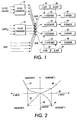
- Fig. 1 is a schematic representation of exemplary image paths
- Fig. 2 illustrates a method of obtaining uncorrelated TRC corrections, by calculating calibration tables
- Fig. 3 is a visualization of a TRC lookup table
- Fig. 4 is a flow diagram of a preferred method of the present invention.
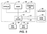
- Fig. 5 is an exemplary embodiment of an image processing apparatus incorporating printer control and color balance calibration in accordance with embodiments of the present invention.
- Fig. 1 depicted is an exemplary image path which may reside wholly or in part within one machine, such as a controller driving a printer or press, and another part may reside in the press or printer itself.
- Color converters 10 and 12 are used to convert from one color space to another. Such devices can, for instance, be implemented on a computer, using a programming language, and their operation is well known to one of ordinary skill in the art. One description of how this conversion can be accomplished is described in International Color Consortium (ICC) standard specifications.
- One-dimensional lookup tables 14 are used for calibrating the press or printer. The outputs from color converter 10 or 12 serve as the input to the one-dimensional lookup tables 14 . The outputs of lookup tables 14 are connected to screeners 16-22 .
- Each of these screeners receives an additional input from respective memory units 24-30. These memory units contain screening threshold values for the different color channels.
- the outputs from screeners 16-22 are provided to a corresponding imaging device 32-38 .
- the imaging device may employ an ink nozzle, acoustic emitter or other device which emits small drops of ink.
- the imaging device could be a laser or LED light source, which images onto a photoconductive drum or belt.
- imaging devices including those which emit material other than ink such as, for example, ionographic imagers where ions are directed to an electroreceptor or thermal devices that direct heat to thermally sensitive material.
- Prior art calibration methods can generally be classified into two categories.
- a first set of calibration methods calibrate the individual channels of a printer separately, without including interactions between the channels.
- a second set of calibration methods incorporate such interaction between the channels.
- CMY first color space
- a predefined value in a second color space e.g., L * a * b * , or any other suitable color space, or density space.
- Both sets of calibration methods obtain the printer calibration by applying one-dimensional corrections to the CMY channels as accomplished by the lookup tables 14 .
- corrections are not correlated across color channels.
- a certain predefined response is defined, such as linear in L * , independent of the other channels.
- the calibration process brings the response of each channel in agreement with the reference response. Since the definition of the reference response for each channel is independent of the other channels the calibration process is reasonably simple and straightforward.
- a wedge having desired percentages p i for each of the printer channels is printed and measured by a sensor, such as a densitometer. From these measurements a one-dimensional correction is constructed for each printer channel that produces the desired response for each of the desired printer channel percentages (p i ) and each of the printer channels.
- the one-dimensional correction is typically implemented by applying a correction to the respective data channel, usually via a tone reproduction curve (TRC) lookup table in the image path.
- TRC lookup table often has 256 values which corresponds to an 8-bit image channel.
- the correction may be applied by selection of halftone threshold values.
- p i printer channel percentages
- some form of interpolation is used to determine the corrected values for these unprinted percentages.
- the TRC method is widely practiced in the industry, and the halftone threshold method has been described by Borg in U.S. Patent No. 5,625,716 and by Crean et al. in U.S. Patent Application serial No. 09/221,239 filed December 28, 1998. This reference and other U.S. Patents and U.S. Patent Applications referred to in the following discussion are hereby incorporated by reference.
- Calibration methods of this first set are easily extendible to other types of printers having more than four channels, for instance printers with CMYK-OG channels, also known as Hexachrome® printers, or for printers with CMYK-RGB channels (Kuppers ink set).
- Hexachrome® is a registered trademark of Pantone, Inc. of New Jersey.
- Quadrant 1 shows a desired output 40 for one channel. This could, for instance, be linear in density, or linear in delta E with respect to white paper where delta E is a measure of color difference in L * a * b * color space.
- Quadrant 2 depicts a measured printer output response 42 of a device without any correction applied in the image path.
- a one-dimensional TRC correction 44 is constructed by mapping an input value (C-input 46) to an output value (C-output 48) such that the desired output 40 is obtained.
- Line 49 in quadrant 3 represents a linear function that maps measured response values 42 to C-output values 48 that will produce the desired output for corresponding C-input values 46.
- Fig. 3 provides a visual representation of a TRC 50.
- An input C, M, Y or K value is found on the horizontal LUT input value axis 52.
- a vertical line from the determined position on the horizontal axis intersects the TRC curve 50 at a point that determines the LUT output value 54 in terms of C, M, Y or K respectively as read from the vertical axis.
- the second set of calibration methods is similar to the first set in the sense that one-dimensional corrections are applied to the individual channels, however, in these methods the individual one-dimensional corrections are correlated to each other.
- the correlation is commonly of a kind that assures predefined CMY values produce predefined L * a * b * values, usually providing a corrected color. This is often referred to as a process for obtaining color balance calibration.
- the one-dimensional correction is typically implemented using a TRC lookup table in a manner similar to the first set of methods.
- a Gray Balance Example C M Y L' a' b' K 0 0 0 100 0 0 0 10 9 9 92 0.3 -0.3 10 20 18 18 84 0.6 -0.6 20 30 27 27 76 0.9 -0.9 30 40 36 36 68 1.2 -1.2 40 50 45 45 60 1.5 -1.5 50 60 54 54 52 1.8 -1.8 60 70 63 63 44 2.1 -2.1 70 80 72 72 36 2.4 -2.4 80 90 81 81 28 2.7 -2.7 90 100 90 90 20 3 -3 100
- the first group uses a small number of patches (approximately 200 or so) which are printed on the printer and then a printer model is applied to obtain a relation between CMY combinations and produced L * a * b * values (See Balasubramanian, "Accuracy of Various Types of Neugebauer Model", IS&T and SID's Color Imaging Conference: Transforms and Transportability of Color, pp. 32-37,1993).
- the first group uses a large number of patches (approximately 1000 or so) printed on the device and then measured.
- the relation between the CMY combinations and L * a * b * values is obtained through a form of interpolation. In both cases, printing is accomplished using the same image path shown in Fig.1, but without any corrections in the image path, so the TRC curves are not changing the input data.
- the correlated one-dimensional TRCs are obtained in the following manner.
- the relation between the CMY values and the produced L * a * b * of the printer is inverted. This can be done in many ways; see for instance Plettinck et al., US Patent No. 05689349, "Method and device for generating printing data in a color space defined for non-standard printing inks".
- the inverted relation allows mapping any given L * a * b * value onto a respective CMY combination that will produce the given L * a * b * value.
- Applying this method for the L * a * b * values of Fig. 2 the CMY values that produce these desired L * a * b * values are obtained. Mapping the CMY values listed in Table 1, onto these CMY values yields the one-dimensional correlated corrections.
- the second group of calibration methods use process control techniques, and prints the CMY patches as listed in Table 1.
- the L * a * b * values for these patches are measured and a feedback loop is constructed.
- the differences in produced and desired L * a * b * values are used as control signals, and from these signals, corrections to the CMY values are obtained that will produce L * a * b * values closer to the desired values.
- the process is repeated until the produced L * a * b * values are within a predetermined proximity of the desired values.
- the TRCs are constructed using the same techniques as used for the first group of methods.
- a more detailed explanation of the second group of methods is given in Mestha et al., U.S. Patent Application serial No.
- both sets share the same disadvantages.
- 8-bit image path channels where the individual channels are all 8-bit values, the potential image quality problems occur.
- Applying corrections to 8-bit values, and keeping the results of this correction as an 8-bit value can produce banding and/or contouring, i.e., visual steps reducing the image quality. This can be seen in smooth vignettes and contone images with smooth gradations.
- Noise is often added to vignettes, masking the potential banding problems.
- the noise is generally made several levels in amplitude and is generated with a frequency that does not beat with the halftone, a challenge that potentially produces some perceptual image quality degradation.
- noise can be applied in vignettes without a great visual loss in image quality, the same cannot be said for adding noise to images. When this is done, the quality of the images is often degraded and, therefore, adding noise to images is not an acceptable solution to the problem.
- an aspect of the calibration and control methods is performing color-balance calibration and control on the halftones while they are in a high quantization resolution form.
- an iterative color balancing process is used with an in situ sensor to perform real-time measurements on the substrate.
- the iterative color balancing method has the advantage of being independent of the marking technique, and can be applied in real-time. Using the high quantization halftone enables contour-free calibration.
- Halftones can be designed to possess many possible fill patterns.
- Halftones with multiple dots for example, can possess a fill sequence with thousands of levels.
- halftones are often stored and used at 8 bits per pixel resulting in 256 levels for uniform input areas.
- Halftone arrays usually exist in three forms: a fine quantization form, typically referred to as a fill-order array, wherein the sequence for turning on each sub-pixel in a unit cell is specified, a coarse quantization form often referred to as a threshold array wherein a pixel value above which a sub-pixel is turned on is stored at its location in the fill-order array, and a direct mapped, or lookup table based, process wherein an output sub-pixel string is stored for each input pixel value and each output pixel in a unit cell. It is also possible to implement something between the first two cases. For example, a halftone with 65,536 pixels requires 16 bits to store the complete fill order. Instead of quantizing all the way down to 8 bit thresholds, fill sequence values can be grouped to give a quantization at 10 bits/pixel for example. The 10 bit case is less likely to produce contouring than the 8 bit case.
- Gray balance calibration (or in general, color balance) is currently obtained by applying one-dimensional correlated 8 bit color lookup tables in the image path. This limits the image quality of existing systems due to calibration or control of the halftone in a low quantization state, or due to subsequent application of an 8-bit lookup table in the image path.
- dots are designed in the fine quantization, fill order view, yielding in many cases 500 to 65,536 halftone levels.
- 256 are selected for the threshold array representation, selecting levels to give equal changes in visual perception, thus packing the levels in the regions where the system response changes most rapidly.
- levels since the range of steepest change can vary with system tuning, substrate type and history, levels must be allocated across all regions where the systems response could change. For any particular state of the system, some levels are kept, and those in regions which, at any given time, do not have a strong response are deleted. Thus the spacing of levels is always wider than would be possible where the allocation of levels have been optimized for the current response.
- image quality is improved by building all system considerations into the threshold array using a high resolution form of the halftone. That is, the present methods avoid contours and poor color balance associated with the existing systems.
- the processes for the calibrations and controls use elements that are optimized for the overall system needs. For example, color balance is performed using the high resolution form of the halftone array, and system controls and calibrations are performed using the high resolution form of the array.
- the first step 60 of the method consists of defining combinations of ink the system will use to print the images. This can be done in different ways, as has, for example, been described in "A Color to Colorant Transformation for a Seven Ink Process", Harold Boll, IS&T's third technical Symposium on Proofing and Printing, 1993. This step has been described in prior literature and will, therefore, not be described in detail here.
- CMYK printing press for example, these combinations are CMY and K.
- the discussion here is limited to the explanation of the preferred embodiment for the CMYK case. It shall, however, be clear to one of ordinary skill in the art how to extend the method to any type of press or printer having more than 4 inks.
- a second step 62 of the method consists of defining a certain desired response for the above-described combinations.
- the response of the press is assumed to be close to the response of a typical offset press, as can be found in the definition of the Specification for Web Offset Printing (SWOP) conditions, provided by the Graphics Arts Technical Foundation (GATF).
- SWOP Web Offset Printing
- GATF Graphics Arts Technical Foundation
- Such a response provides for a color for some combinations of CMY.
- An example of such a color balance can be found in Table 1. It also specifies the desired response for the K-channel.
- a third step 64 determines an approximate set of CMY values that approximate the desired response. Before doing this, it is generally useful to characterize the toe (highlight) and shoulder (saturated) regions of the engine response, where varying C, M and Y produces no significant change in L * a * b * , to make sure that none of the chosen CMY values fall in these regions.
- a fourth step 66 of the method is to print a number of predefined CMY patches, these patches being defined by the previous step (64), i.e., they belong to the set of the patches as defined in step 3.
- a fifth step 68 includes measuring the printed patches and determining selected color space values, such as the CIE L * a * b * values.
- a sixth step 70 is to determine the difference between the desired response and the responses determined in the fifth step (68) and amplify these differences.
- a gain matrix converts the L * a * b * differences into CMY differences.
- the gain matrix corresponding to each predetermined CMY patch is predetermined from a first set of input-output characterizations of the printer and is stored in a memory (not shown). This assumes that the CMY to L * a * b * conversion is linear, which is not completely the case, but it is close enough to reality for the method to work. It is also assumed that the dots have been designed so the relationship between L * a * b * and whatever quantity is being used to characterize the C, M, or Y level (fractional area coverage, for example) is smooth and well behaved.
- a seventh step 72 adds the amplified differences in the 6th step (70), and add them to previously determined amplified differences determined in previous iterations of the 6th step (70) . This means that steps 5 and further will be repeated several times and the amplified differences integrated in the 6th step (70) over the different iterations.
- An eighth step 74 takes the corrections from the 7th step (72) and adds the corrections to the initial approximations of the CMY values determined in the 3rd step (64).
- a ninth step 76 is to print the CMY values determined in the 8th step (74).
- Steps 5, 6, 7, 8 and 9 are repeated, until the output is close to a desired output as determined at the tenth step 78.
- the system has converged to a state in which the mapping of the input CMY is obtained in order to produce the desired CIE L * a * b * values.
- the eleventh step 80 of the method consists of interpolating, extrapolating, and smoothing these curves to obtain the desired response along the neutral axis.
- the curves are normally extended to intersect the L * axis at the requested amount of C, M, and Y, where some C, M, and Y are actually deposited.
- these values are normally offset a considerable amount from zero - i. e., very small dots generally do not print at all.
- the curves must be warped so they smoothly approach 100% as the requested L * approaches its minimum value. This maybe done using the approach discussed in U.S. Patent Application serial No. 09/817,186 filed March 27, 2001 (Smooth Monotonic tone Reproduction Curve End Point Adjustment).
- a twelfth step 82 of the method consists of determining the K curves.
- the CIE L * a * b * values of the patches are measured using the in situ densitometer.
- the fourteenth step 86 is computational. It comprises determining K-curves using input K values and the measured L * values (a * and b * values are discarded from this measurement).
- the desired K-curve is determined by using standard interpolation and smoothing techniques discussed previously.
- the fifteenth step 88 of the method consists of recalculating the screening threshold-level array for each of the CMYK channels, for all possible CMYK input values.
- the one-dimensional correlated transform curves are used as interpolation functions to select threshold values from the fill order array.
- CMY and K for a pixel sent from the digital front-end (DFE) to the printer is dependent only on the document content and the relatively static color mixing properties of the system.
- the pixels sent from the DFE are not dependent on the specific response of the print engine at a certain point in time.
- the CMYK values represent values related to visual quantity such as L * .
- Most of the system variability is optimally handled by building it into the threshold array.
- contone bytes are not directly related to visual perception, but have special meaning in cases such as pixels on an antialiased edge, cases which can be marked by a tag value or inferred by context.
- the averaging (or similar linear operation) on a set of pixels does not yield the L * over the large pixel, but the encoded value is used by the rendering logic to recover the correct position of the edge.
- the rendering logic expects the pixel stream from the raster image processor (RIP) to be independent of the current state of the engine so that preprogrammed logic can be applied to the pixel stream to develop the special case rendering. Handling most of the system variability in threshold array preserves the integrity of the input pixel stream.
- Fig. 5 shows an exemplary embodiment of an image processing apparatus 100 incorporating printer control and color balance calibration in accordance with the present application.
- An image data source 102 , an input device 104 and an image output device 106 are connected to the image processing apparatus 100 over links 108 , 110 and 112 , respectively.
- the image data source 102 can be a digital camera, a scanner, a locally or remotely located computer, an electrophotographic printing system in a xerographic environment, or any other known or later developed device that is capable of generating or otherwise providing electronic image data.
- the image data source 102 can be any suitable device that stores and/or transmits electronic image data, such as a client or a server of a network.
- the image data source 102 can be integrated with the image processing apparatus 100 , or the image data source 102 can be connected to the image processing apparatus 100 over a connection device, such as a modem, a local area network, a wide area network, an intranet, the Internet, any other distributed processing network, or any other known or later developed connection device.
- a connection device such as a modem, a local area network, a wide area network, an intranet, the Internet, any other distributed processing network, or any other known or later developed connection device.
- the image output device 106 can be integrated with the image processing apparatus 100 , or the image output device can be connected to the image processing apparatus 100 over a connection device, such as a modem, a local area network, a wide area network, an intranet, the Internet, any other distributed processing network, or any other known or later developed connection device.
- the image output device 106 may also be any other known or later developed device which is capable of receiving electronic image data over the link 112 from the image processing apparatus 100 .
- the link 112 can thus be any known or later developed system or device for transmitting the electronic image data from the image processing apparatus 100 to the image output terminal.
- the image processing apparatus 100 shown in Fig. 5 is connected to the image output device 106 over link 112.
- the image output terminal 106 may be an integral part of the image processing apparatus 100 .
- An example of this alternative configuration would be a digital copier or the like.
- the image processing apparatus 100 can be any known or later developed type of image processing apparatus. There is no restriction on the form the image processing apparatus 100 can take.
- the input device 104 can be any known or later developed device for providing control information from a user to the image processing apparatus 100.
- the input device 104 can be a control panel of the image processing apparatus 100 , or could be a control program executing on a locally or remotely located general purpose computer, or the like.
- the link 110 can be any known or later developed device for transmitting control signals and input data from the input device 104 to the image processing apparatus 100 .
- the image processing apparatus 100 includes a controller 120 , an input/output interface 122 , a memory 124 , and a calibration circuit 126 .
- the controller 120, memory 124 and calibration circuit 126 are connected to the input/output interface 122 , and to each other via a bus 128.
- the electronic image data from the image data source 102, and any control and/or data signals from the input device 104, are input through the I/O interface 122 , and, under control of the controller 120 , are stored in the memory 124 and/or provided to the controller 120 .
- the memory 124 preferably has at least an alterable portion and may include a fixed portion.
- the alterable portion of the memory 124 can be implemented using static or dynamic RAM, a floppy disk and disk drive, a hard disk and disk drive, flash memory, or any other known or later developed alterable volatile or non-volatile memory device. If the memory includes a fixed portion, the fixed portion can be implemented using a ROM, a PROM, an EPROM, and EEPROM, a CD-ROM and disk drive, a DVD-ROM and disk drive, a writable optical disk and disk drive, or any other known or later developed fixed memory device.
- An in situ sensor 130 is in communication with the I/O interface 122 via link 132 .
- the in situ sensor 130 is provided for measuring color patches printed according to concepts of the present application.
- the in situ sensor and corresponding link 132 are capable of measuring and sending data in a high quantization format.
- Link 132 is capable of sending data comprising more than 8 bits, either by having a data path wider than 8 bits or by sending data serially or in packets of bytes.
- the image data path 112 can also be 8 bit wide or wider. It should also be clear that the in-situ sensor can be replaced by an offline sensor.
- the links 108, 110, 112 and 132 can be any known or later developed device or system for connection, including a direct cable connection, a connection over a wide area network or a local area network, a connection over an intranet, a connection over the Internet, or a connection over any other distributed processing network or system.
- the links 108, 110, 112 and 132 can be any known or later developed connection system or structure usable for connection as described above which may be achieved as wireline connections and wireless connections.
- the calibration unit 126 may be provided as a separate device from the image processing apparatus 100. That is, the calibration unit 126 may be a separate device attachable upstream of a stand-alone image processing apparatus 100 .
- the calibration unit 126 maybe a separate device which interfaces with both the image data source 102 and the image processing apparatus 100 .
- the calibration unit 126 may be implemented as software on the image processing apparatus 100 or the image data source 102 .
- Other configurations of the elements shown in Fig. 5 may be used without departing from the spirit and scope of this invention.
Landscapes
- Engineering & Computer Science (AREA)
- Multimedia (AREA)
- Signal Processing (AREA)
- Facsimile Image Signal Circuits (AREA)
- Color Image Communication Systems (AREA)
- Color, Gradation (AREA)
Applications Claiming Priority (2)
| Application Number | Priority Date | Filing Date | Title |
|---|---|---|---|
| US342873 | 2003-01-15 | ||
| US10/342,873 US7277196B2 (en) | 2003-01-15 | 2003-01-15 | Iterative printer control and color balancing system and method using a high quantization resolution halftone array to achieve improved image quality with reduced processing overhead |
Publications (2)
| Publication Number | Publication Date |
|---|---|
| EP1441504A2 true EP1441504A2 (fr) | 2004-07-28 |
| EP1441504A3 EP1441504A3 (fr) | 2005-12-21 |
Family
ID=32594857
Family Applications (1)
| Application Number | Title | Priority Date | Filing Date |
|---|---|---|---|
| EP04000647A Ceased EP1441504A3 (fr) | 2003-01-15 | 2004-01-14 | Système et méthode d'équilibrage des couleurs utilisant un tableau de demi-teintes avec une résolution hautement quantifiée |
Country Status (2)
| Country | Link |
|---|---|
| US (1) | US7277196B2 (fr) |
| EP (1) | EP1441504A3 (fr) |
Cited By (2)
| Publication number | Priority date | Publication date | Assignee | Title |
|---|---|---|---|---|
| EP1648157A1 (fr) * | 2004-10-13 | 2006-04-19 | GMG GmbH & Co. KG | Procédé d'optimisation d'impression en polychromie |
| DE102006040609A1 (de) * | 2006-08-30 | 2008-03-20 | OCé PRINTING SYSTEMS GMBH | Verfahren und Anordnung zum Ermitteln einer Farbzuordnung von Quellfarben und Zielfarben |
Families Citing this family (43)
| Publication number | Priority date | Publication date | Assignee | Title |
|---|---|---|---|---|
| US7315394B2 (en) * | 2003-02-25 | 2008-01-01 | Xerox Corporation | Calibration method for an imaging device |
| DE102004009271A1 (de) * | 2004-02-26 | 2005-09-15 | Man Roland Druckmaschinen Ag | Verfahren zur Farbregelung an Druckmaschinen |
| JP4442879B2 (ja) * | 2004-07-28 | 2010-03-31 | キヤノン株式会社 | 画像形成装置及び色信号変換方法 |
| KR100636185B1 (ko) * | 2004-10-22 | 2006-10-19 | 삼성전자주식회사 | 컬러 프린터의 색조 보상 방법 및 색조 보상부를 포함하는컬러 프린터 |
| US8014024B2 (en) * | 2005-03-02 | 2011-09-06 | Xerox Corporation | Gray balance for a printing system of multiple marking engines |
| US7397581B2 (en) | 2005-04-01 | 2008-07-08 | Xerox Corporation | TRC smoothing algorithm to improve image contours in 1D color controls |
| US8203768B2 (en) | 2005-06-30 | 2012-06-19 | Xerox Corporaiton | Method and system for processing scanned patches for use in imaging device calibration |
| US8259369B2 (en) | 2005-06-30 | 2012-09-04 | Xerox Corporation | Color characterization or calibration targets with noise-dependent patch size or number |
| US7864364B2 (en) * | 2005-08-09 | 2011-01-04 | Xerox Corporation | Color correction of images |
| US8154777B2 (en) * | 2005-08-09 | 2012-04-10 | Xerox Corporation | Color compensation of images |
| US7706031B2 (en) * | 2005-09-30 | 2010-04-27 | Xerox Corporation | Pitch to pitch online gray balance calibration with dynamic highlight and shadow controls |
| US8711435B2 (en) * | 2005-11-04 | 2014-04-29 | Xerox Corporation | Method for correcting integrating cavity effect for calibration and/or characterization targets |
| US7719716B2 (en) * | 2005-11-04 | 2010-05-18 | Xerox Corporation | Scanner characterization for printer calibration |
| US7826090B2 (en) * | 2005-12-21 | 2010-11-02 | Xerox Corporation | Method and apparatus for multiple printer calibration using compromise aim |
| US8102564B2 (en) | 2005-12-22 | 2012-01-24 | Xerox Corporation | Method and system for color correction using both spatial correction and printer calibration techniques |
| US7483186B2 (en) * | 2006-07-03 | 2009-01-27 | Xerox Corporation | Pitch to pitch online gray balance calibration |
| US7751734B2 (en) * | 2006-09-26 | 2010-07-06 | Xerox Corporation | Color sensor to measure single separation, mixed color or IOI patches |
| US7583418B2 (en) * | 2006-09-26 | 2009-09-01 | Xerox Corporation | Array based sensor to measure single separation or mixed color (or IOI) patches on the photoreceptor using MEMS based hyperspectral imaging technology |
| US7623278B2 (en) * | 2006-09-26 | 2009-11-24 | Xerox Corporation | MEMS Fabry-Perot inline color scanner for printing applications using stationary membranes |
| US7593134B2 (en) * | 2006-10-23 | 2009-09-22 | Xerox Corporation | Color rendering control system |
| US7639410B2 (en) * | 2006-12-11 | 2009-12-29 | Xerox Corporation | Optimal test patch selection for multi-media printing systems using low rank approximation |
| US7969624B2 (en) * | 2006-12-11 | 2011-06-28 | Xerox Corporation | Method and system for identifying optimal media for calibration and control |
| US7869087B2 (en) * | 2007-03-31 | 2011-01-11 | Xerox Corporation | Color printer characterization or calibration to correct for spatial non-uniformity |
| US7548705B2 (en) * | 2007-04-03 | 2009-06-16 | Xerox Corporation | Systems and methods for marking test patches for calibrating and/or visually confirming color accuracy of a marking device |
| US7864320B2 (en) * | 2007-04-19 | 2011-01-04 | Xerox Corporation | Method to minimize instrument differences in color management functions |
| US7773222B2 (en) * | 2008-05-27 | 2010-08-10 | Xerox Corporation | UV enhanced full width array scanning spectrophotometer |
| US8958081B2 (en) * | 2008-05-27 | 2015-02-17 | Xerox Corporation | Spot color control method, apparatus and system |
| US8654402B2 (en) * | 2008-05-27 | 2014-02-18 | Xerox Corporation | Pitch based high quantization halftone dot linearization for rendering high quality color images |
| US7961322B2 (en) * | 2008-05-27 | 2011-06-14 | Xerox Corporation | Method for conditional application of color measurement error compensation in spectral sensors |
| JP5132428B2 (ja) * | 2008-05-28 | 2013-01-30 | キヤノン株式会社 | 情報処理装置、方法、及び、プログラム |
| US8282182B2 (en) * | 2008-08-22 | 2012-10-09 | Ricoh Production Print Solutions LLC | Correction of print engine artifacts using an iterative halftoning search algorithm |
| US8204303B2 (en) * | 2009-05-08 | 2012-06-19 | Xerox Corporation | Spatially based transformation of spot colors |
| JP2011077844A (ja) * | 2009-09-30 | 2011-04-14 | Seiko Epson Corp | 印刷装置およびキャリブレーション方法 |
| US8571268B2 (en) * | 2010-03-19 | 2013-10-29 | Xerox Corporation | On-paper image quality metric using on-belt sensing |
| US8736840B1 (en) * | 2010-05-23 | 2014-05-27 | Arkady Ten | Method for finding an aim position of a measuring device |
| US8542418B2 (en) | 2010-08-25 | 2013-09-24 | Ricoh Production Print Solutions LLC | Printer calibration for printers with fixed print array structures |
| JP5617567B2 (ja) * | 2010-11-30 | 2014-11-05 | コニカミノルタ株式会社 | キャリブレーションシステム、キャリブレーション方法及びプログラム |
| GB2534186A (en) | 2015-01-15 | 2016-07-20 | Landa Corp Ltd | Printing system and method |
| US8870319B2 (en) | 2012-05-02 | 2014-10-28 | Xerox Corporation | System and method for printing with ink limiting |
| US9811771B2 (en) * | 2016-03-29 | 2017-11-07 | Xerox Corporation | User tone reproduction curve ink limit warning |
| US11057543B2 (en) | 2018-03-12 | 2021-07-06 | Hewlett-Packard Development Company, L.P. | Updating a lookup table for an imaging system |
| US11351802B2 (en) | 2020-09-10 | 2022-06-07 | Guangdong Ocean University | Model inversion-based iterative learning control method for printer and printer system |
| CN111993801B (zh) * | 2020-09-10 | 2021-07-13 | 广东海洋大学 | 基于反演模型的打印机迭代学习控制方法及打印机系统 |
Citations (7)
| Publication number | Priority date | Publication date | Assignee | Title |
|---|---|---|---|---|
| US2297691A (en) * | 1939-04-04 | 1942-10-06 | Chester F Carlson | Electrophotography |
| US5949967A (en) * | 1997-12-12 | 1999-09-07 | Eastman Kodak Company | Transforming input color values to device control signals |
| US6027201A (en) * | 1995-05-01 | 2000-02-22 | Minnesota Mining And Manufacturing Company | Recalibrating a multi-color imaging system |
| US6061501A (en) | 1997-03-25 | 2000-05-09 | International Business Machines Corporation | System, method and program for converting an externally defined four colorant (CMYK) into an equivalent four dimensional colorant defined in terms of the four inks (C'M'Y'K') that are associated with a given printer |
| JP2001169105A (ja) * | 1999-12-13 | 2001-06-22 | Ricoh Co Ltd | 画像処理方法、画像処理装置、画像形成方法及び記憶媒体 |
| EP1152598A2 (fr) | 2000-05-05 | 2001-11-07 | Xerox Corporation | Système de calibrage en ligne d'un appareil de génération de couleur variant dynamiqument |
| EP1185076A1 (fr) * | 2000-07-27 | 2002-03-06 | Hewlett-Packard Company, A Delaware Corporation | Generation dynamique d'une matrice a demi-tons linearisee |
Family Cites Families (12)
| Publication number | Priority date | Publication date | Assignee | Title |
|---|---|---|---|---|
| US4933754A (en) * | 1987-11-03 | 1990-06-12 | Ciba-Geigy Corporation | Method and apparatus for producing modified photographic prints |
| BE1004659A5 (nl) | 1991-03-01 | 1993-01-05 | Barco Graphics Nv | Werkwijze en inrichting voor het transformeren van een kleurcoordinatenset. |
| BE1006960A5 (nl) | 1993-04-30 | 1995-01-31 | Barco Graphics Nv | Werkwijze en inrichting voor het genereren van drukdata. |
| US5625716A (en) | 1994-03-15 | 1997-04-29 | Adobe Systems Incorporated | Method for compensating for transfer characteristics of a printing system in a halftone screening process |
| US5995714A (en) * | 1996-02-16 | 1999-11-30 | Eastman Kodak Company | Method for printer calibration |
| US5920407A (en) * | 1997-01-09 | 1999-07-06 | Hewlett-Packard Company | Method and apparatus for applying tonal correction to image data |
| US6178007B1 (en) | 1997-01-21 | 2001-01-23 | Xerox Corporation | Method for continuous incremental color calibration for color document output terminals |
| US6008907A (en) * | 1997-10-15 | 1999-12-28 | Polaroid Corporation | Printer calibration |
| US6236474B1 (en) * | 1998-05-22 | 2001-05-22 | Xerox Corporation | Device independent color controller and method |
| JP2000255108A (ja) * | 1999-03-08 | 2000-09-19 | Fuji Photo Film Co Ltd | プリンタのキャリブレーション方法及び装置並びにプリンタ |
| US6435654B1 (en) * | 1999-11-29 | 2002-08-20 | Xerox Corporation | Color calibration for digital halftoning |
| US6714319B1 (en) | 1999-12-03 | 2004-03-30 | Xerox Corporation | On-line piecewise homeomorphism model prediction, control and calibration system for a dynamically varying color marking device |
-
2003
- 2003-01-15 US US10/342,873 patent/US7277196B2/en not_active Expired - Lifetime
-
2004
- 2004-01-14 EP EP04000647A patent/EP1441504A3/fr not_active Ceased
Patent Citations (8)
| Publication number | Priority date | Publication date | Assignee | Title |
|---|---|---|---|---|
| US2297691A (en) * | 1939-04-04 | 1942-10-06 | Chester F Carlson | Electrophotography |
| US6027201A (en) * | 1995-05-01 | 2000-02-22 | Minnesota Mining And Manufacturing Company | Recalibrating a multi-color imaging system |
| US6061501A (en) | 1997-03-25 | 2000-05-09 | International Business Machines Corporation | System, method and program for converting an externally defined four colorant (CMYK) into an equivalent four dimensional colorant defined in terms of the four inks (C'M'Y'K') that are associated with a given printer |
| US5949967A (en) * | 1997-12-12 | 1999-09-07 | Eastman Kodak Company | Transforming input color values to device control signals |
| JP2001169105A (ja) * | 1999-12-13 | 2001-06-22 | Ricoh Co Ltd | 画像処理方法、画像処理装置、画像形成方法及び記憶媒体 |
| US7106476B1 (en) * | 1999-12-13 | 2006-09-12 | Ricoh Company, Ltd. | Image processing method, image processing apparatus, image forming method and recording medium |
| EP1152598A2 (fr) | 2000-05-05 | 2001-11-07 | Xerox Corporation | Système de calibrage en ligne d'un appareil de génération de couleur variant dynamiqument |
| EP1185076A1 (fr) * | 2000-07-27 | 2002-03-06 | Hewlett-Packard Company, A Delaware Corporation | Generation dynamique d'une matrice a demi-tons linearisee |
Non-Patent Citations (1)
| Title |
|---|
| GAURAV SHARMA: "Digital Color Imaging Handbook", 23 December 2002, CRC PRESS, USA, ISBN: 0-8493-0900-X, pages: 424 - 429, XP007916087 * |
Cited By (3)
| Publication number | Priority date | Publication date | Assignee | Title |
|---|---|---|---|---|
| EP1648157A1 (fr) * | 2004-10-13 | 2006-04-19 | GMG GmbH & Co. KG | Procédé d'optimisation d'impression en polychromie |
| DE102006040609A1 (de) * | 2006-08-30 | 2008-03-20 | OCé PRINTING SYSTEMS GMBH | Verfahren und Anordnung zum Ermitteln einer Farbzuordnung von Quellfarben und Zielfarben |
| DE102006040609B4 (de) * | 2006-08-30 | 2009-07-02 | OCé PRINTING SYSTEMS GMBH | Verfahren und Anordnung zum Ermitteln einer Farbzuordnung von Quellfarben und Zielfarben |
Also Published As
| Publication number | Publication date |
|---|---|
| EP1441504A3 (fr) | 2005-12-21 |
| US20040136015A1 (en) | 2004-07-15 |
| US7277196B2 (en) | 2007-10-02 |
Similar Documents
| Publication | Publication Date | Title |
|---|---|---|
| US7277196B2 (en) | Iterative printer control and color balancing system and method using a high quantization resolution halftone array to achieve improved image quality with reduced processing overhead | |
| US7069164B2 (en) | Method for calibrating a marking system to maintain color output consistency across multiple printers | |
| EP1152598B1 (fr) | Système de calibrage en ligne d'un appareil de génération de couleur variant dynamiqument | |
| JP4976348B2 (ja) | 印刷システムのカラー印刷ジョブ出力のマッチング | |
| US7206100B2 (en) | Image processing method and apparatus | |
| US8259369B2 (en) | Color characterization or calibration targets with noise-dependent patch size or number | |
| US7295703B2 (en) | Method for scanner characterization for color measurement of printed media having four or more colorants | |
| JP5310298B2 (ja) | 画像処理装置、画像形成システム、およびプログラム | |
| US7315394B2 (en) | Calibration method for an imaging device | |
| JP5699765B2 (ja) | 画像処理装置、画像処理方法および画像処理プログラム | |
| US6616262B2 (en) | Image processing apparatus performing printer calibration | |
| JP2018133801A (ja) | 動的印刷システム補償機構 | |
| US6919972B2 (en) | Image processing apparatus and its control method, and image processing method | |
| US6330078B1 (en) | Feedback method and apparatus for printing calibration | |
| US8253975B2 (en) | Method and apparatus for calibration of a color printer | |
| CN104869281A (zh) | 颜色处理装置、图像形成装置和图像形成方法 | |
| US10922591B2 (en) | Image forming apparatus | |
| US20060227386A1 (en) | Digital scanner calibration | |
| US8149454B2 (en) | Color printing | |
| US20040150858A1 (en) | Method, apparatus and system for image data correction | |
| JP5848190B2 (ja) | プロファイル作成装置及び方法、色変換装置及び方法、プログラム並びに印刷システム | |
| US8654402B2 (en) | Pitch based high quantization halftone dot linearization for rendering high quality color images | |
| US20040080763A1 (en) | System and method for adjusting color reproduction | |
| US6893105B2 (en) | Method for printing an image from a halftone binary bitmap using multiple exposures | |
| Fairport et al. | Van de Capelle et al.(45) Date of Patent: Oct. 2, 2007 |
Legal Events
| Date | Code | Title | Description |
|---|---|---|---|
| PUAI | Public reference made under article 153(3) epc to a published international application that has entered the european phase |
Free format text: ORIGINAL CODE: 0009012 |
|
| AK | Designated contracting states |
Kind code of ref document: A2 Designated state(s): AT BE BG CH CY CZ DE DK EE ES FI FR GB GR HU IE IT LI LU MC NL PT RO SE SI SK TR |
|
| AX | Request for extension of the european patent |
Extension state: AL LT LV MK |
|
| PUAL | Search report despatched |
Free format text: ORIGINAL CODE: 0009013 |
|
| AK | Designated contracting states |
Kind code of ref document: A3 Designated state(s): AT BE BG CH CY CZ DE DK EE ES FI FR GB GR HU IE IT LI LU MC NL PT RO SE SI SK TR |
|
| AX | Request for extension of the european patent |
Extension state: AL LT LV MK |
|
| 17P | Request for examination filed |
Effective date: 20060621 |
|
| 17Q | First examination report despatched |
Effective date: 20060731 |
|
| AKX | Designation fees paid |
Designated state(s): DE FR GB |
|
| STAA | Information on the status of an ep patent application or granted ep patent |
Free format text: STATUS: THE APPLICATION HAS BEEN REFUSED |
|
| 18R | Application refused |
Effective date: 20160407 |