EP1441508A2 - Bildverarbeitung mit Minimierung von Überschwingungsartefakten und Rauschen - Google Patents
Bildverarbeitung mit Minimierung von Überschwingungsartefakten und Rauschen Download PDFInfo
- Publication number
- EP1441508A2 EP1441508A2 EP03104976A EP03104976A EP1441508A2 EP 1441508 A2 EP1441508 A2 EP 1441508A2 EP 03104976 A EP03104976 A EP 03104976A EP 03104976 A EP03104976 A EP 03104976A EP 1441508 A2 EP1441508 A2 EP 1441508A2
- Authority
- EP
- European Patent Office
- Prior art keywords
- filter
- local variance
- variance
- maximum
- threshold
- Prior art date
- Legal status (The legal status is an assumption and is not a legal conclusion. Google has not performed a legal analysis and makes no representation as to the accuracy of the status listed.)
- Ceased
Links
- 238000000034 method Methods 0.000 claims abstract description 23
- 230000007704 transition Effects 0.000 claims description 9
- 230000009467 reduction Effects 0.000 description 24
- 230000004044 response Effects 0.000 description 7
- 239000000872 buffer Substances 0.000 description 6
- 230000015654 memory Effects 0.000 description 6
- 238000001914 filtration Methods 0.000 description 5
- 230000008569 process Effects 0.000 description 5
- 230000000694 effects Effects 0.000 description 4
- 230000003044 adaptive effect Effects 0.000 description 3
- 238000010586 diagram Methods 0.000 description 2
- 230000008030 elimination Effects 0.000 description 2
- 238000003379 elimination reaction Methods 0.000 description 2
- 230000006870 function Effects 0.000 description 2
- 238000012423 maintenance Methods 0.000 description 2
- 230000004075 alteration Effects 0.000 description 1
- 230000008901 benefit Effects 0.000 description 1
- 230000003139 buffering effect Effects 0.000 description 1
- 238000004364 calculation method Methods 0.000 description 1
- 238000003707 image sharpening Methods 0.000 description 1
- 230000004048 modification Effects 0.000 description 1
- 238000012986 modification Methods 0.000 description 1
- 230000010355 oscillation Effects 0.000 description 1
- 238000006467 substitution reaction Methods 0.000 description 1
Images


Classifications
-
- H—ELECTRICITY
- H04—ELECTRIC COMMUNICATION TECHNIQUE
- H04N—PICTORIAL COMMUNICATION, e.g. TELEVISION
- H04N5/00—Details of television systems
- H04N5/14—Picture signal circuitry for video frequency region
- H04N5/21—Circuitry for suppressing or minimising disturbance, e.g. moiré or halo
-
- H—ELECTRICITY
- H04—ELECTRIC COMMUNICATION TECHNIQUE
- H04N—PICTORIAL COMMUNICATION, e.g. TELEVISION
- H04N19/00—Methods or arrangements for coding, decoding, compressing or decompressing digital video signals
- H04N19/50—Methods or arrangements for coding, decoding, compressing or decompressing digital video signals using predictive coding
- H04N19/503—Methods or arrangements for coding, decoding, compressing or decompressing digital video signals using predictive coding involving temporal prediction
- H04N19/51—Motion estimation or motion compensation
- H04N19/527—Global motion vector estimation
-
- H—ELECTRICITY
- H04—ELECTRIC COMMUNICATION TECHNIQUE
- H04N—PICTORIAL COMMUNICATION, e.g. TELEVISION
- H04N19/00—Methods or arrangements for coding, decoding, compressing or decompressing digital video signals
- H04N19/80—Details of filtering operations specially adapted for video compression, e.g. for pixel interpolation
-
- H—ELECTRICITY
- H04—ELECTRIC COMMUNICATION TECHNIQUE
- H04N—PICTORIAL COMMUNICATION, e.g. TELEVISION
- H04N5/00—Details of television systems
- H04N5/14—Picture signal circuitry for video frequency region
- H04N5/20—Circuitry for controlling amplitude response
- H04N5/205—Circuitry for controlling amplitude response for correcting amplitude versus frequency characteristic
- H04N5/208—Circuitry for controlling amplitude response for correcting amplitude versus frequency characteristic for compensating for attenuation of high frequency components, e.g. crispening, aperture distortion correction
Definitions
- This invention relates to image processing, and more particularly to processing image data for display on a digital display device.
- Scaling the original image means generating a new image that is larger or smaller than the original.
- the new image will have a larger or smaller number of pixels in the horizontal and /or vertical directions than the original image.
- a larger image is scaled up (more new pixels); a smaller image is scaled down (fewer newer pixels).
- a simple case is a 2:1 increase or decrease in size. A 2:1 decrease could be done by throwing away every other pixel (although this simple method results in poor image quality). For a 2:1 increase, new pixels can be generated in between the old by various interpolation methods.
- the scaling process is implemented with various scaling algorithms, also called “filters”, which treat the rows and columns of the image as discrete time-domain signals.
- filters which treat the rows and columns of the image as discrete time-domain signals.
- the image signal is a sampled version of the original analog image and has an inherent sample rate that results in a fixed number of pixels in the image.
- To rescale the image it is resampled at some new, predetermined rate to provide the desired number of pixels. This is done by convolving the rows and columns of the original image with various low-pass filter functions to provide sample values at each of the output image pixel locations. Scaling is performed in two passes. Typically, the rows are rescaled first (horizontal scaling), then the new rows are used for resealing the columns (vertical scaling).
- a feature of some vertical and horizontal scaling filters is a high frequency emphasis. These scaling filters have stronger gain, greater than unity, in the high-frequency region of their passband than in the low-frequency region of their passband. Although this emphasis can be useful for sharpening the image, it can result in artifacts. High frequency emphasis filtering can also be used for image data that does not require scaling, to achieve image sharpness.
- One aspect of the invention is a method of reducing ringing artifacts in image data after it has been filtering with a high frequency emphasis filter. It is assumed that the filter has a number of filter taps, such as a multi-tap polyphase filter.
- a local variance is calculated as the difference between the unfiltered maximum and minimum values at neighboring filter taps. This local variance is compared to a large-transition threshold. If the local variance is greater than the large-transition threshold, the filtered data value is limited to a value between unfiltered maximum and minimum values at neighboring taps. If the local variance is less than the large transition threshold, the filtered data value is not limited. This process is repeated for each data value, using new neighboring tap values.
- An advantage of the ringing minimization method is that it permits the use of high frequency emphasis filtering without introducing ringing artifacts.
- the high frequency filtering can be performed for sharpness in connection with image scaling, or on data that is already in the correct resolution.
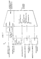
- FIGURE 1 is a block diagram of an image processing system 10, having both a horizontal scaling unit 12 and a vertical scaling unit 14.
- Horizontal scaling unit 12 performs horizontal position counter maintenance and implements a horizontal scaling filter.
- Vertical scaling unit 14 performs vertical position counter maintenance and implements a vertical scaling filter.
- Scaling units 12 and 14 may be implemented with various commercially available processing systems.
- a calculation unit 15 computes and stores various values used during image processing.
- horizontal scaling unit 12 is a polyphase filter with five taps per phase.
- Vertical scaling unit 14 is a polyphase filter with three taps per phase.
- Look-up tables (LUTs) 17 and 18 store the filter coefficients, and may be implemented with RAM devices. In the example of this description, LUT 17 stores 639 coefficients and LUT 18 stores 383 coefficients. Both LUTs 17 and 18 are sized accordingly.
- a horizontal line buffer 11 stores input values for the horizontal scaling unit 12, and a vertical line buffer 13 stores data lines for the vertical scaling unit 14.
- Horizontal line buffer 11 has three FIFO units, one for each color (red, green, blue).
- Vertical line buffer 13 has nine line memories, three per color, corresponding to the three tap filter. Because the horizontal filter is before the vertical filter, the size of the line memories is at least as large as the maximum horizontal output resolution.
- a feature of system 10 is that data buffering for the filters is accomplished without frame buffers. In other words, there is no need to store a whole image frame at once. However, the ringing minimization and noise reduction methods and systems described herein are also useful with image processing systems that do use frame buffers.
- FIGURES 2 to 6 and the accompanying description below describe one feature of image processing system 10 -- the elimination of ringing artifacts when horizontal scaling unit 12 or vertical scaling unit 14, or both, are implemented as high frequency emphasis filters.
- the high frequency emphasis is the result of the particular filter coefficients stored in LUTs 17 and 18. As explained in the Background, the high frequency emphasis provides image sharpening. Ringing minimization units 40 and 50 implement the ringing minimization feature of the invention.
- FIGURES 7 to 10 describe a second feature of image processing system 10 -- the modification of the filter coefficients stored in LUTs 17 and 18 so as to reduce noise.
- Noise reduction units 70 and 80 implement this feature of the invention.
- ringing minimization units 40 and 50 and noise reduction units 70 and 80 are used in connection with scaling units 12 and 14.
- these features are also useful in an image processing system that does not perform scaling. For example, an image that does not require scaling could be sharpened using a high frequency emphasis filter, therefore giving rise to a need for ringing minimization.
- FIGURE 2 illustrates an example of the frequency response of a typical high frequency emphasis filter, such as filter 12 or 14 when so implemented. As illustrated, such filters have stronger gain in the high frequency region of their pass band than in the low frequency region of their pass band.
- FIGURE 3 illustrates the spatial result of a high frequency emphasis filter, compared to a non high frequency emphasis filter.
- the high frequency emphasis filter does provide a sharpening effect. However, it also produces a ringing artifact, caused by the filter's underdamped response. In other words, the filter produces oscillations near high frequency edges.
- ringing minimization units 40 and 50 process the output from the horizontal scaling unit 12 and vertical scaling unit 14, respectively. As explained below, these units 40 and 50 calculate a local variance of the unfiltered input signal, and limit the filtered data they receive from the respective scaling units 12 and 14. They are "adaptive" in the sense that they adaptively determine when to limit the filtered data to local minimum and maximum values.
- FIGURE 4 illustrates ringing minimization unit 40, which receives the output of horizontal scaling unit 12.
- Unit 40 is implemented with logic circuitry, thus FIGURE 4 further illustrates the process of minimizing the ringing artifact that would otherwise exist in the output of horizontal scaling unit 12.
- Ringing minimization unit 40 is duplicated for each color, thus there are three ringing minimization units 40 at the output of horizontal scaling unit 12.
- Limiter 47 receives the filtered output of the horizontal scaling filter within horizontal scaling unit 12, which has a high frequency emphasis. It also receives local maximum and minimum values of the unscaled data, as determined by maximum and minimum finders 41 and 42.
- unscaled input data samples, x(n) are delivered to four maximum/minimum finding circuits, which may be implemented with conventional logic circuitry. Two of these circuits are a five-tap maximum finder 43 and a five-tap minimum finder 44, which find the maximum and minimum values of the input data within the five tap window of horizontal scaling unit 12.
- Maximum finder 41 and minimum finder 42 are used to determine the minimum and maximum of the three input data values closest to the center tap.
- a comparator 45 receives the local variance value and a programmable large transition threshold. The result of the comparison is delivered to a limiter 47.
- An optional AND gate 46 may be used to AND the output of the comparator 45 with a flag, to turn the ringing circuit on or off.
- limiter 47 limits the output of horizontal scaling unit 12 between the maximum and minimum of the three input values closest to the center tap, that is, to the local maximum and minimum input values.
- limiter 47 does not limit the filter output data to input values.
- Multiplexers 48 and 49 are used together with AND gate 46 to turn the ringing minimization on and off.
- Multiplexer 48 receives the local maximum and the maximum of the input data range (typically 255).
- Multiplexer 49 receives the local minimum and the minimum of the input data range (typically 0). If ringing minimization is "on”, as determined by AND gate 45, multiplexers 48 and 49 deliver the local maximum and minimum values to limiter 47. If ringing minimization is "off”, as determined by AND gate 46, multiplexers 48 and 49 deliver the maximum and minimum over the input data range.
- FIGURE 5 illustrates ringing minimization unit 50, which receives the output of vertical scaling unit 14.
- Unit 50 is implemented with logic circuitry 50, thus FIGURE 5 further illustrates the process of minimizing the ringing artifact that would otherwise exist in the output of vertical scaling unit 14.
- Limiter 57 operates in much the same manner as limiter 47 of unit 40. It receives the filtered output of the vertical scaling filter within vertical scaling unit 12, which as stated above, has a high frequency emphasis. It also receives local maximum and minimum values of the unscaled data, as determined by maximum and minimum finders 51 and 52.
- Unscaled input data samples, x(n), are delivered to two maximum/minimum finders 51 and 52, which may be implemented with conventional logic circuitry.
- Maximum and minimum finders 51 and 52 are used to determine the maximum and minimum values of the input data within the three tap window of vertical scaling unit 14.
- a comparator 55 receives this difference, as well as a programmable large transition threshold.
- the results of the comparison are delivered to limiter 57. If the local variance is greater than or equal to the large transition threshold, limiter 57 limits the output of filter 14 between the minimum and maximum values within the filter. Otherwise, the results of the filter 14 are allowed to pass through ringing minimization unit 50 unaltered.
- the "neighboring filter taps" used for determining the local variance, as well as for determining the limiting values of the limiter can vary. These taps can be the same number of taps as the filter, or can be a subset.
- the unit 40 could be like unit 50, having a single set of maximum/minimum finder circuits.
- any of the maximum/minimum finder circuits of either unit could use a different number of neighboring filter taps.
- neighborhboring filter taps is meant all or some of the filter taps within the n-tap filter window that produced a particular data value.
- FIGURE 6 illustrates the filtered output of FIGURE 3, but with the above-described ringing minimization applied to the output. As illustrated, the ringing artifact has been eliminated, but the sharp edge transition is maintained.
- the local variance values described above may also be used to perform spatial noise reduction. In general, this method involves determining whether a local variance within an image is low or high and whether the variance represents an edge or noise. If it represents noise, the high frequency portion of the filter is adjusted down. Like the ringing minimization method described above, the noise reduction method is adaptive and affects the filter output according to values of neighboring filter taps.
- FIGURE 7 illustrates a noise reduction unit 70 to be used in associated with horizontal scaling unit 12. It is designed for LUT 17, which has 639 coefficients and does not require additional memory.
- the horizontal filter tap locations are delivered to a logic circuit 71, which determines whether the input is greater than the value 319. If so, that value is subtracted from 638.
- logic unit 71 provides linear filter coefficients that are symmetrical around the center tap, in this case 0 to 319 and then to 0. As explained below, the resulting values are used to alter the coefficients stored in LUT 17.
- Multiplexer 74 selects between three classes of filter coefficients: normal (as stored in LUT 17), linear, and a "semi-linear" combination of normal and linear filter coefficients. Two variance levels are used to define three frequency bins, which determine which filter is to be delivered to the horizontal scaling unit 12.
- a local variance value is delivered to each of two comparators 72 and 73.
- this local variance may be the same value as described above in connection with FIGURE 4. If system 10 is implemented with noise reduction and not ringing minimization, additional circuitry similar to that described in connection with FIGURE 4 may be added to noise reduction unit 70 to compute the local variance.
- Comparators 72 and 73 compare the local variance value to the first and second thresholds, respectively. When the local variance is less than the first threshold, the center tap is assumed to be lying within a flat field or low frequency region. Instead of using the coefficients in the LUT 17, multiplexer 74 selects coefficients for a linear filter. The coefficients of the linear filter are derived from the filter tap locations, as determined by circuit 71. The linear filter is a severe low pass filter, and will remove high frequency low level noise. In effect, the filter coefficients stored in LUT 17 are modified so as to re-configure the scaling filter within horizontal scaling unit 12 as a semi-linear filter.
- FIGURE 8 illustrates the frequency response of a typical horizontal scaling filter, as compared to the horizontal linear filter whose coefficients are derived in noise reduction unit 70.
- the pass band of the linear filter is about one-third the size of the pass band of the typical scaling filter.
- the center tap is assumed to be in a mid-frequency region.
- a less severe low pass filter is used in these regions. It is derived from a combination between the linear filter described above and the scaling filter adjusted for sharpness. The amplitude of the horizontal linear filter is halved and subsequently averaged with the coefficients of the horizontal scaling filter. Each phase is normalized after the filtering operation occurs. In effect, the filter coefficients stored in LUT 17 are modified so as to re-configure the scaling filter within horizontal scaling unit 12 as a "semi-linear" filter.
- FIGURE 9 illustrates the frequency response of a typical horizontal scaling filter, as compared to the combined filter described in the preceding paragraph.
- This filter is "semi-linear" in the sense that the output is between that of the linear filter of FIGURE 8 and that of a typical scaling filter.
- Multiplexer 70 delivers the filter coefficients stored in LUT 18, which in the example of this description, represent a scaling filter.
- FIGURE 10 illustrates how the noise reduction circuit of FIGURE 7 is modified for use with the vertical scaling engine 14.
- circuit 100 is the same as described above for circuit 70, except in the case where the variance is between the first and second variance thresholds.
- the average of the vertical linear filter and the vertical scaling filter is used. Otherwise, multiplexer 84, and logic circuits 81, 82, and 83 operate in much the same manner as the comparable circuits described above in connection with FIGURE 7.
- Horizontal (Linear/2 + LUT Coefficients)/2
- Vertical (Linear + LUT Coefficients)/2
- the noise reduction circuits 70 and 100 provide adaptive noise reduction with no increased memory requirement.
- the registers and line memories used to perform scaling are incorporated into the noise reduction circuitry.
- the filter coefficients for noise reduction do not need to be stored in memory. They are derived from a simple function that relates filter coefficients to filter tap location.
- noise reduction can be performed even when the input resolution is the same as the output resolution. Noise reduction can also be performed with a high frequency emphasis filter. The resulting image has a lower noise floor and sharper edges.
- both the ringing minimization units 40 and 50 and noise reduction units 70 and 80 use the same local variance values.
- system 10 may implement either ringing minimization or noise reduction and not necessarily both.
Landscapes
- Engineering & Computer Science (AREA)
- Multimedia (AREA)
- Signal Processing (AREA)
- Image Processing (AREA)
- Picture Signal Circuits (AREA)
- Apparatus For Radiation Diagnosis (AREA)
Applications Claiming Priority (2)
| Application Number | Priority Date | Filing Date | Title |
|---|---|---|---|
| US331567 | 1981-12-17 | ||
| US10/331,567 US7254277B2 (en) | 2002-12-30 | 2002-12-30 | Image processing with minimization of ringing artifacts and noise |
Publications (2)
| Publication Number | Publication Date |
|---|---|
| EP1441508A2 true EP1441508A2 (de) | 2004-07-28 |
| EP1441508A3 EP1441508A3 (de) | 2008-01-16 |
Family
ID=32594766
Family Applications (1)
| Application Number | Title | Priority Date | Filing Date |
|---|---|---|---|
| EP03104976A Ceased EP1441508A3 (de) | 2002-12-30 | 2003-12-24 | Bildverarbeitung mit Minimierung von Überschwingungsartefakten und Rauschen |
Country Status (2)
| Country | Link |
|---|---|
| US (2) | US7254277B2 (de) |
| EP (1) | EP1441508A3 (de) |
Cited By (1)
| Publication number | Priority date | Publication date | Assignee | Title |
|---|---|---|---|---|
| EP2111037A3 (de) * | 2008-04-17 | 2011-10-19 | Sony Corporation | Bildverarbeitungsvorrichtung, Bilderfassungsvorrichtung, Bildverarbeitungsverfahren und Programm |
Families Citing this family (19)
| Publication number | Priority date | Publication date | Assignee | Title |
|---|---|---|---|---|
| US7254277B2 (en) * | 2002-12-30 | 2007-08-07 | Texas Instruments Incorporated | Image processing with minimization of ringing artifacts and noise |
| US7339601B2 (en) * | 2003-07-10 | 2008-03-04 | Samsung Electronics Co., Ltd. | Methods of suppressing ringing artifact of decompressed images |
| JP2006093884A (ja) * | 2004-09-21 | 2006-04-06 | Oki Electric Ind Co Ltd | フィルタ装置 |
| JP2008539542A (ja) * | 2005-04-28 | 2008-11-13 | コーニンクレッカ フィリップス エレクトロニクス エヌ ヴィ | 投影システム、及び投影システムを動作させる方法 |
| JP2007048176A (ja) * | 2005-08-12 | 2007-02-22 | Fujifilm Holdings Corp | デジタル信号処理装置 |
| US7619639B1 (en) * | 2005-09-12 | 2009-11-17 | Nvidia Corporation | Adaptive scaling using a programmable video engine |
| KR100707268B1 (ko) * | 2005-10-08 | 2007-04-16 | 삼성전자주식회사 | 영상보간장치 및 영상보간방법 |
| US8115967B2 (en) * | 2006-11-28 | 2012-02-14 | Silverbrook Research Pty Ltd | Localized signal data preservation within signal bandwidth |
| US8817909B2 (en) * | 2006-11-29 | 2014-08-26 | Intel Mobile Communications GmbH | Polar modulator arrangement, polar modulation method, filter arrangement and filtering method |
| US8224076B2 (en) * | 2006-11-29 | 2012-07-17 | Panasonic Corporation | Image processing method and image processing apparatus |
| US10123050B2 (en) * | 2008-07-11 | 2018-11-06 | Qualcomm Incorporated | Filtering video data using a plurality of filters |
| US8279240B2 (en) * | 2008-09-29 | 2012-10-02 | Intel Corporation | Video scaling techniques |
| TWI456982B (zh) * | 2010-03-30 | 2014-10-11 | Realtek Semiconductor Corp | 影像處理裝置與空間影像雜訊消除方法 |
| US10575021B2 (en) * | 2012-07-03 | 2020-02-25 | Telefonaktiebolaget Lm Ericsson (Publ) | Controlling deblocking filtering |
| TWI600284B (zh) | 2016-11-16 | 2017-09-21 | 國立清華大學 | 數值尋找器以及數值尋找方法 |
| US10623738B2 (en) * | 2017-04-06 | 2020-04-14 | Futurewei Technologies, Inc. | Noise suppression filter |
| US10684537B2 (en) | 2017-11-14 | 2020-06-16 | Texas Instruments Incorporated | Camera-assisted arbitrary surface characterization and correction |
| US10681318B2 (en) | 2017-11-14 | 2020-06-09 | Texas Instruments Incorporated | Camera-assisted arbitrary surface characterization and slope-based correction |
| NO20210105A1 (en) | 2018-12-27 | 2021-01-28 | Halliburton Energy Services Inc | Removal of signal ringdown noise |
Citations (1)
| Publication number | Priority date | Publication date | Assignee | Title |
|---|---|---|---|---|
| US5880767A (en) * | 1996-09-11 | 1999-03-09 | Hewlett-Packard Company | Perceptual image resolution enhancement system |
Family Cites Families (17)
| Publication number | Priority date | Publication date | Assignee | Title |
|---|---|---|---|---|
| GB2262854B (en) * | 1991-12-24 | 1995-05-24 | Sony Broadcast & Communication | Image processing apparatus |
| GB9321372D0 (en) * | 1993-10-15 | 1993-12-08 | Avt Communications Ltd | Video signal processing |
| US6141446A (en) * | 1994-09-21 | 2000-10-31 | Ricoh Company, Ltd. | Compression and decompression system with reversible wavelets and lossy reconstruction |
| US5940536A (en) * | 1995-09-05 | 1999-08-17 | Matsushita Electric Industrial Co., Ltd. | Ringing detector and filter |
| US5819035A (en) * | 1995-10-20 | 1998-10-06 | Matsushita Electric Industrial Co., Ltd. | Post-filter for removing ringing artifacts of DCT coding |
| US5926791A (en) * | 1995-10-26 | 1999-07-20 | Sony Corporation | Recursively splitting the low-frequency band with successively fewer filter taps in methods and apparatuses for sub-band encoding, decoding, and encoding and decoding |
| KR100242636B1 (ko) * | 1996-03-23 | 2000-02-01 | 윤종용 | 블록화효과 및 링잉노이즈 감소를 위한 신호적응후처리시스템 |
| US6188799B1 (en) * | 1997-02-07 | 2001-02-13 | Matsushita Electric Industrial Co., Ltd. | Method and apparatus for removing noise in still and moving pictures |
| US6847737B1 (en) * | 1998-03-13 | 2005-01-25 | University Of Houston System | Methods for performing DAF data filtering and padding |
| US6574374B1 (en) * | 1999-04-14 | 2003-06-03 | Intel Corporation | Enhancing image compression performance by morphological processing |
| US6579238B1 (en) * | 2000-04-24 | 2003-06-17 | Acuson Corporation | Medical ultrasonic imaging system with adaptive multi-dimensional back-end mapping |
| CA2317870A1 (en) * | 2000-09-08 | 2002-03-08 | Jaldi Semiconductor Corp. | A system and method for scaling images |
| US7057627B2 (en) * | 2001-03-05 | 2006-06-06 | Broadcom Corporation | Video and graphics system with square graphics pixels |
| US6993191B2 (en) * | 2001-05-04 | 2006-01-31 | Pts Corporation | Methods and apparatus for removing compression artifacts in video sequences |
| US6950473B2 (en) * | 2002-06-21 | 2005-09-27 | Seiko Epson Corporation | Hybrid technique for reducing blocking and ringing artifacts in low-bit-rate coding |
| US7254277B2 (en) * | 2002-12-30 | 2007-08-07 | Texas Instruments Incorporated | Image processing with minimization of ringing artifacts and noise |
| KR20040100735A (ko) * | 2003-05-24 | 2004-12-02 | 삼성전자주식회사 | 영상보간장치 및 영상보간방법 |
-
2002
- 2002-12-30 US US10/331,567 patent/US7254277B2/en not_active Expired - Lifetime
-
2003
- 2003-12-24 EP EP03104976A patent/EP1441508A3/de not_active Ceased
-
2007
- 2007-08-01 US US11/832,279 patent/US7970230B2/en not_active Expired - Lifetime
Patent Citations (1)
| Publication number | Priority date | Publication date | Assignee | Title |
|---|---|---|---|---|
| US5880767A (en) * | 1996-09-11 | 1999-03-09 | Hewlett-Packard Company | Perceptual image resolution enhancement system |
Non-Patent Citations (1)
| Title |
|---|
| JHA R ET AL: "Edge adaptive filtering: how much and which direction?", 19891114; 19891114 - 19891117, 14 November 1989 (1989-11-14), pages 364 - 366, XP010091465 * |
Cited By (2)
| Publication number | Priority date | Publication date | Assignee | Title |
|---|---|---|---|---|
| EP2111037A3 (de) * | 2008-04-17 | 2011-10-19 | Sony Corporation | Bildverarbeitungsvorrichtung, Bilderfassungsvorrichtung, Bildverarbeitungsverfahren und Programm |
| US8121429B2 (en) | 2008-04-17 | 2012-02-21 | Sony Corporation | Image processing apparatus, image-capturing apparatus, image processing method, and program |
Also Published As
| Publication number | Publication date |
|---|---|
| EP1441508A3 (de) | 2008-01-16 |
| US20040125113A1 (en) | 2004-07-01 |
| US7970230B2 (en) | 2011-06-28 |
| US7254277B2 (en) | 2007-08-07 |
| US20070269129A1 (en) | 2007-11-22 |
Similar Documents
| Publication | Publication Date | Title |
|---|---|---|
| US7970230B2 (en) | Image processing with minimization of ringing artifacts and noise | |
| US5959693A (en) | Pixel adaptive noise reduction filter for digital video | |
| US8406547B2 (en) | Visual processing device, visual processing method, program, display device, and integrated circuit | |
| US5757977A (en) | Fuzzy logic filter for reducing noise and sharpening edges of digital image signals | |
| US7782401B1 (en) | Method and system for digital image scaling with sharpness enhancement and transient improvement | |
| Lee et al. | Adaptive scan rate up-conversion system based on human visual characteristics | |
| US8885967B2 (en) | Method and apparatus for content adaptive sharpness enhancement | |
| EP1383311A1 (de) | Digitale Rauschverminderungstechniken | |
| EP1190388A2 (de) | System und verfahren zur verbesserung der schärfe von einem videobild | |
| US7551795B2 (en) | Method and system for quantization artifact removal using super precision | |
| KR100970525B1 (ko) | 화상 처리 장치 | |
| JP2005142891A (ja) | 画像処理方法及び画像処理装置 | |
| US7511769B2 (en) | Interframe noise reduction for video | |
| Song et al. | Hardware-efficient debanding and visual enhancement filter for inverse tone mapped high dynamic range images and videos | |
| EP1909227A1 (de) | Verfahren und Vorrichtung zur Minimierung von Überschwingungsartefakten in einem Eingangsbild | |
| JP4380498B2 (ja) | ブロック歪み低減装置 | |
| JP4475255B2 (ja) | 画像処理装置 | |
| CN101964907B (zh) | 一种去区块装置及方法 | |
| US7570306B2 (en) | Pre-compensation of high frequency component in a video scaler | |
| US8090210B2 (en) | Recursive 3D super precision method for smoothly changing area | |
| US8508662B1 (en) | Post de-interlacer motion adaptive filter for smoother moving edges | |
| Cho | Adaptively rate-controlled shoot suppression | |
| JP2001036769A (ja) | ノイズ低減装置 | |
| KR100192777B1 (ko) | 다양한 윈도우 크기를 갖는 메디안 필터 | |
| WO2002039735A1 (en) | Video signal processing |
Legal Events
| Date | Code | Title | Description |
|---|---|---|---|
| PUAI | Public reference made under article 153(3) epc to a published international application that has entered the european phase |
Free format text: ORIGINAL CODE: 0009012 |
|
| AK | Designated contracting states |
Kind code of ref document: A2 Designated state(s): AT BE BG CH CY CZ DE DK EE ES FI FR GB GR HU IE IT LI LU MC NL PT RO SE SI SK TR |
|
| AX | Request for extension of the european patent |
Extension state: AL LT LV MK |
|
| RIN1 | Information on inventor provided before grant (corrected) |
Inventor name: KEMPF, JEFFREY Inventor name: SKOOG, ARNOLD P Inventor name: IKEDA, ROGER M. |
|
| PUAL | Search report despatched |
Free format text: ORIGINAL CODE: 0009013 |
|
| AK | Designated contracting states |
Kind code of ref document: A3 Designated state(s): AT BE BG CH CY CZ DE DK EE ES FI FR GB GR HU IE IT LI LU MC NL PT RO SE SI SK TR |
|
| AX | Request for extension of the european patent |
Extension state: AL LT LV MK |
|
| RIC1 | Information provided on ipc code assigned before grant |
Ipc: H04N 5/21 20060101ALI20071210BHEP Ipc: H04N 7/30 20060101AFI20071210BHEP |
|
| 17P | Request for examination filed |
Effective date: 20080716 |
|
| AKX | Designation fees paid |
Designated state(s): DE FR GB |
|
| RBV | Designated contracting states (corrected) |
Designated state(s): DE FR GB NL |
|
| 17Q | First examination report despatched |
Effective date: 20170309 |
|
| STAA | Information on the status of an ep patent application or granted ep patent |
Free format text: STATUS: THE APPLICATION HAS BEEN REFUSED |
|
| 18R | Application refused |
Effective date: 20190616 |