EP1442332B1 - Räumliche lichtmodulatorvorrichtung - Google Patents
Räumliche lichtmodulatorvorrichtung Download PDFInfo
- Publication number
- EP1442332B1 EP1442332B1 EP02756709.8A EP02756709A EP1442332B1 EP 1442332 B1 EP1442332 B1 EP 1442332B1 EP 02756709 A EP02756709 A EP 02756709A EP 1442332 B1 EP1442332 B1 EP 1442332B1
- Authority
- EP
- European Patent Office
- Prior art keywords
- dmd
- pattern
- light modulator
- spatial light
- pattern image
- Prior art date
- Legal status (The legal status is an assumption and is not a legal conclusion. Google has not performed a legal analysis and makes no representation as to the accuracy of the status listed.)
- Expired - Lifetime
Links
- 230000003287 optical effect Effects 0.000 claims description 63
- 238000005286 illumination Methods 0.000 claims description 58
- 239000000872 buffer Substances 0.000 claims description 7
- 238000002156 mixing Methods 0.000 claims description 5
- 238000003384 imaging method Methods 0.000 claims description 3
- 230000001960 triggered effect Effects 0.000 claims description 3
- 230000004044 response Effects 0.000 claims 2
- 230000008901 benefit Effects 0.000 description 8
- 238000000034 method Methods 0.000 description 8
- 238000010586 diagram Methods 0.000 description 5
- 238000002474 experimental method Methods 0.000 description 4
- 238000013461 design Methods 0.000 description 3
- 230000006870 function Effects 0.000 description 3
- 229910052736 halogen Inorganic materials 0.000 description 3
- 150000002367 halogens Chemical class 0.000 description 3
- 102000004169 proteins and genes Human genes 0.000 description 3
- 108090000623 proteins and genes Proteins 0.000 description 3
- 239000007787 solid Substances 0.000 description 3
- 230000003595 spectral effect Effects 0.000 description 3
- 230000001419 dependent effect Effects 0.000 description 2
- 230000000694 effects Effects 0.000 description 2
- 238000005516 engineering process Methods 0.000 description 2
- 238000002376 fluorescence recovery after photobleaching Methods 0.000 description 2
- 210000000554 iris Anatomy 0.000 description 2
- 238000000386 microscopy Methods 0.000 description 2
- 238000012986 modification Methods 0.000 description 2
- 230000004048 modification Effects 0.000 description 2
- 230000008685 targeting Effects 0.000 description 2
- 230000002123 temporal effect Effects 0.000 description 2
- 238000007792 addition Methods 0.000 description 1
- 230000002411 adverse Effects 0.000 description 1
- 230000033228 biological regulation Effects 0.000 description 1
- 238000004113 cell culture Methods 0.000 description 1
- 230000008859 change Effects 0.000 description 1
- 238000006243 chemical reaction Methods 0.000 description 1
- 238000000576 coating method Methods 0.000 description 1
- 238000004891 communication Methods 0.000 description 1
- 238000010276 construction Methods 0.000 description 1
- 230000008878 coupling Effects 0.000 description 1
- 238000010168 coupling process Methods 0.000 description 1
- 238000005859 coupling reaction Methods 0.000 description 1
- 230000005284 excitation Effects 0.000 description 1
- 239000007850 fluorescent dye Substances 0.000 description 1
- 238000002372 labelling Methods 0.000 description 1
- 239000004973 liquid crystal related substance Substances 0.000 description 1
- 238000005259 measurement Methods 0.000 description 1
- 230000010287 polarization Effects 0.000 description 1
- 230000008569 process Effects 0.000 description 1
- 238000011084 recovery Methods 0.000 description 1
- 230000003252 repetitive effect Effects 0.000 description 1
- 238000009987 spinning Methods 0.000 description 1
- 238000010561 standard procedure Methods 0.000 description 1
- 230000001360 synchronised effect Effects 0.000 description 1
- 238000012546 transfer Methods 0.000 description 1
Images


Classifications
-
- G—PHYSICS
- G02—OPTICS
- G02B—OPTICAL ELEMENTS, SYSTEMS OR APPARATUS
- G02B21/00—Microscopes
- G02B21/06—Means for illuminating specimens
-
- G—PHYSICS
- G02—OPTICS
- G02B—OPTICAL ELEMENTS, SYSTEMS OR APPARATUS
- G02B21/00—Microscopes
- G02B21/06—Means for illuminating specimens
- G02B21/08—Condensers
- G02B21/088—Condensers for both incident illumination and transillumination
-
- G—PHYSICS
- G02—OPTICS
- G02B—OPTICAL ELEMENTS, SYSTEMS OR APPARATUS
- G02B21/00—Microscopes
- G02B21/36—Microscopes arranged for photographic purposes or projection purposes or digital imaging or video purposes including associated control and data processing arrangements
- G02B21/365—Control or image processing arrangements for digital or video microscopes
-
- G—PHYSICS
- G09—EDUCATION; CRYPTOGRAPHY; DISPLAY; ADVERTISING; SEALS
- G09G—ARRANGEMENTS OR CIRCUITS FOR CONTROL OF INDICATING DEVICES USING STATIC MEANS TO PRESENT VARIABLE INFORMATION
- G09G3/00—Control arrangements or circuits, of interest only in connection with visual indicators other than cathode-ray tubes
- G09G3/20—Control arrangements or circuits, of interest only in connection with visual indicators other than cathode-ray tubes for presentation of an assembly of a number of characters, e.g. a page, by composing the assembly by combination of individual elements arranged in a matrix no fixed position being assigned to or needed to be assigned to the individual characters or partial characters
- G09G3/34—Control arrangements or circuits, of interest only in connection with visual indicators other than cathode-ray tubes for presentation of an assembly of a number of characters, e.g. a page, by composing the assembly by combination of individual elements arranged in a matrix no fixed position being assigned to or needed to be assigned to the individual characters or partial characters by control of light from an independent source
- G09G3/3433—Control arrangements or circuits, of interest only in connection with visual indicators other than cathode-ray tubes for presentation of an assembly of a number of characters, e.g. a page, by composing the assembly by combination of individual elements arranged in a matrix no fixed position being assigned to or needed to be assigned to the individual characters or partial characters by control of light from an independent source using light modulating elements actuated by an electric field and being other than liquid crystal devices and electrochromic devices
- G09G3/346—Control arrangements or circuits, of interest only in connection with visual indicators other than cathode-ray tubes for presentation of an assembly of a number of characters, e.g. a page, by composing the assembly by combination of individual elements arranged in a matrix no fixed position being assigned to or needed to be assigned to the individual characters or partial characters by control of light from an independent source using light modulating elements actuated by an electric field and being other than liquid crystal devices and electrochromic devices based on modulation of the reflection angle, e.g. micromirrors
-
- G—PHYSICS
- G01—MEASURING; TESTING
- G01N—INVESTIGATING OR ANALYSING MATERIALS BY DETERMINING THEIR CHEMICAL OR PHYSICAL PROPERTIES
- G01N21/00—Investigating or analysing materials by the use of optical means, i.e. using sub-millimetre waves, infrared, visible or ultraviolet light
- G01N21/62—Systems in which the material investigated is excited whereby it emits light or causes a change in wavelength of the incident light
- G01N21/63—Systems in which the material investigated is excited whereby it emits light or causes a change in wavelength of the incident light optically excited
- G01N21/64—Fluorescence; Phosphorescence
- G01N21/645—Specially adapted constructive features of fluorimeters
- G01N21/6456—Spatial resolved fluorescence measurements; Imaging
- G01N21/6458—Fluorescence microscopy
-
- G—PHYSICS
- G09—EDUCATION; CRYPTOGRAPHY; DISPLAY; ADVERTISING; SEALS
- G09G—ARRANGEMENTS OR CIRCUITS FOR CONTROL OF INDICATING DEVICES USING STATIC MEANS TO PRESENT VARIABLE INFORMATION
- G09G2300/00—Aspects of the constitution of display devices
- G09G2300/08—Active matrix structure, i.e. with use of active elements, inclusive of non-linear two terminal elements, in the pixels together with light emitting or modulating elements
- G09G2300/0809—Several active elements per pixel in active matrix panels
- G09G2300/0842—Several active elements per pixel in active matrix panels forming a memory circuit, e.g. a dynamic memory with one capacitor
- G09G2300/0857—Static memory circuit, e.g. flip-flop
Definitions
- This invention relates to a spatial light modulator apparatus and system for use in conjunction with an optical microscope.
- Spatial light modulators such as liquid crystal displays (LCDs) and digital mirror devices (DMDs) (as available from Texas Instruments, for example) are used to modulate incident light into a spatial pattern to form a light image corresponding to an electrical or optical input.
- DMDs have been successfully incorporated into video projectors and printers, for example. See U.S. Patent No. 5,535,047 .
- FRAP fluorescence recovery after photobleaching
- the invention results from the realization that instead of designing specially configured microscopes or coupling a complete video projector to an existing microscope, a lower cost spatial light modulator which produces mask pattern images in real time is effected by the combination of a specially designed optical head itself incorporating a DMD and a DMD controller digitally controlled by a digital interface responsive to a computerized pattern generation subsystem to provide a digital drive signal to the DMD controller corresponding to pattern image data produced by the pattern generation subsystem.
- the present invention operates solely in the digital realm by the use of a DMD interface which, in essence, provides to the DMD controller a map of DMD mirror settings corresponding to the mask pattern desired by the user.
- the illumination lamp need not be integral with the modulator apparatus and instead a wide variety of light source inputs may be used.
- the DMD controller is now a simple buffer, the modulator apparatus can be mounted to either the reflected light port, the transmitted light port, or the camera port of the microscope, a laser light input can even be used, and real time imaging accomplished.
- This invention features a spatial light modulator apparatus for an optical microscope system, the apparatus comprising an optical head including a mounting flange for mounting the optical head to a port of the microscope, a spatial light modulator device such as a DMD for generating a pattern image of light, a light source mount for receiving a source of illumination, and one or more optical elements for directing light from the source of illumination to the DMD and to direct the pattern image generated by the DMD to the microscope.
- a DMD controller has a digital input and is connected to the DMD for driving the individual micromirrors of the DMD to generate the pattern image.
- a pattern generation subsystem is configured to output pattern image data and a digital interface is connected between the digital input of the DMD controller and the pattern generation subsystem and configured to provide a digital drive signal to the DMD controller corresponding to the pattern image data.
- the DMD controller is mounted on the optical head adjacent the DMD and the digital interface is housed on a PC card received in a computer and the pattern generation subsystem is operable on the computer.
- the optical head includes a housing with an illumination axis, the DMD is located on the housing on the illumination axis thereof and the mounting flange is located on the housing on the illumination axis thereof opposite the DMD.
- the light source mount is typically located on the optical head housing on an axis transverse to the illumination axis.
- the optical head further includes a light baffle positioned such that when the micromirrors of the DMD are in the off state, light reflected by the DMD is directed to the light baffle.
- the optical microscope has a field plane and the DMD and the optical elements of the optical head may be configured to direct the pattern image generated by the DMD to the field plane of the optical microscope. Alternatively, the DMD and the optical elements of the optical head are configured to direct the pattern image generated by the DMD to a conjugate of the field plane of the optical microscope.
- a camera is typically attached to the microscope, the camera having a field of view and the optical elements of the optical head are configured such that the DMD pattern image fills part or all of the field of view of the camera.
- a light source is typically disposed in the light source mount such as a halogen lamp, a flash lamp, an arc lamp, or a laser light source.
- the light source mount further includes a shutter assembly and a filter holder assembly.
- the optical head may further include a secondary light source mount also with a shutter assembly and a filter holder assembly.
- the optical head may further include a beam splitter mount.
- the digital interface includes a clock which provides a clock signal and a logic device responsive to the pattern image data and the clock signal and configured to assign pixels to the pattern image data and to serialize the assigned pixels according to the clock signal to reformat the pattern image data to correspond to the spatial addressing of the DMD and is further configured to generate a plurality of timing signals based on the clock signal to synchronize serialization of the assigned pixels.
- the plurality of timing signals typically correspond to DMD address counter signals. Several of the plurality of timing signal may be multiplied in frequency by the logic device to provide faster global dark resets of the mirrors of the DMD.
- the logic device is a field programmable gate array and a digital cable connects the digital interface to the digital input of the DMD controller.
- the DMD controller is configured to buffer the reformatted mask image data and to load the memory cells of the DMD.
- the DMD controller is further configured to provide a reset command, a new state command, and a hold command to reset, new state, or hold, respectively, all of the mirrors of the DMD simultaneously.
- the optical microscope includes a camera for imaging the specimen viewed by the microscope live on a display.
- the pattern generation subsystem is configured to output pattern image data and comprises a drawing editor responsive to an input device for drawing a pattern shape and an alpha blending routine responsive to the camera and the drawing editor for representing the drawn pattern shape translucently on the display over the specimen image.
- the digital interface is responsive to the drawing editor to provide a digital drive signal which controls the DMD to generate the pattern image which is identical in shape to the translucent pattern shown on the display.
- the pattern generation subsystem typically further includes a set of stored calibration values and a spatial scale and offset routine interposed between the drawing editor and the digital interface and responsive to the stored calibration values for correlating the pixels of the drawn pattern shape to the pixels of the DMD.
- This invention also features an optical head for a spatial light modulator system, the optical head comprising a mounting flange for mounting the optical head to a port of the microscope, a spatial light modulator device for generating a pattern image of light, a light source mount for receiving a source of illumination, one or more optical elements for directing light from the source of illumination to the spatial light modulator device and to direct the pattern image generated by the spatial light modulator device to a microscope, and a controller connected to the spatial light modulator device for driving the spatial light modulator device to generate the pattern image, the controller having a digital input responsive to a digital drive signal.
- the spatial light modulator device is a DMD located on the housing on the illumination axis thereof and the mounting flange is located on the housing on the illumination axis opposite the DMD.
- This invention also features a digital interface interconnected between a controller for a spatial light modulator device (e.g. a DMD) and a pattern generation subsystem, the digital interface comprising a clock which provides a clock signal and a logic device responsive to pattern image data output by the pattern generation subsystem and the clock signal and configured to assign pixels to the pattern image data and to serialize the assigned pixels according to the clock signal to reformat the pattern image data to correspond to the spatial addressing of the spatial light modulator device and the logic device is further configured to generate a plurality of timing signals based on the clock signal to synchronize serialization of the assigned pixels.
- a controller for a spatial light modulator device e.g. a DMD
- a pattern generation subsystem e.g. a DMD
- the digital interface comprising a clock which provides a clock signal and a logic device responsive to pattern image data output by the pattern generation subsystem and the clock signal and configured to assign pixels to the pattern image data and to serialize the assigned pixels according to the clock signal to reformat the pattern
- the plurality of timing signals usually correspond to DMD address counter signals and several of the said DMD address counter signals are preferably multiplied in frequency by the logic device to provide faster global dark resets.
- the logic device is a programmable logic device or a field programmable gate array and further included is a digital cable connecting the digital interface to a DMD controller connected to the DMD.
- the DMD controller is preferably configured to buffer the reformatted pattern image data and to load the memory cells of the DMD.
- the logic device may be further configured to provide a reset command, a new state command, and a hold command.
- the digital interface is on a PC card received in a computer and wherein the pattern generation subsystem is operable on the computer.
- This invention also features a pattern generation subsystem configured to output a pattern image data to a spatial light modulator (e.g., a DMD), the pattern generation subsystem comprising a drawing editor responsive to an input device for drawing a pattern shape and an alpha blending routine responsive to a camera and the drawing editor for representing the drawn pattern shape translucently on a display over a specimen image.
- a digital interface may be included responsive to the drawing editor to provide a digital drive signal which controls the spatial light modulator to generate the pattern image.
- a set of stored calibration values and a spatial scale and offset routine interposed between the drawing editor and the digital interface and responsive to the stored calibration values for correlating the pixels of the drawn pattern shape to the pixels of the spatial light modulator.
- a spatial light modulator system for an optical microscope features an optical head including a mounting flange for mounting the optical head to either the reflected light port or the transmitted light port of the microscope, a spatial light modulator for generating a pattern image of light, a light source mount for receiving a source of illumination, and one or more optical elements for directing light from the source of illumination to the spatial light modulator and to direct the pattern image generated by the spatial light modulator to the microscope.
- a controller is mounted on the optical head adjacent the spatial light modulator and has a digital input.
- a computer includes a pattern generation subsystem configured to output pattern image data and a digital interface PC card configured to provide a digital drive signal to the controller corresponding to the pattern image data generated by the pattern generation subsystem.
- Fig. 1 for microscope 12 is a complete video projector unit purporting to employ LCD or DMD 14, light source 15, and drive 23 connected via video cable 16 to graphic card 18 of "control/calculating device" 20.
- Device 10 is connected to transmitted light port 22 of microscope 12 and graphics card 18 generates the image signal for driving LCD/DMD 14.
- the other components of this system are described in U.S. Patent No. 6,243,197 . The drawbacks, limitations, and problems associated with such a system are discussed in the background section above.
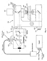
- the spatial light modulator apparatus in one embodiment, includes optical head 30, Fig. 2 with housing 32 having mounting flange 34 thereon for mounting optical head 30 to the reflected light port 36 of microscope 38.
- Optical head 30 may alternatively be mounted to port 40 instead of transmitted light source 41, or even camera port 42 typically employing camera 56.
- Light source mount 44 receives a source of illumination 46 such as a halogen lamp, a flash lamp, an arc lamp, or even a laser light source.
- a source of illumination 46 such as a halogen lamp, a flash lamp, an arc lamp, or even a laser light source.
- Light from illuminated light source 46 is directed to a spatial light modulator device, preferably DMD 48 via optical element 58 (e.g., a mirror) and the pattern generated by DMD 48 is directed via optical elements 52, 54 (e.g., refractive or reflective optical elements or a combination of both) to microscope 38.
- Light baffle 51 is positioned as shown such that when the micromirrors of DMD 48 are in the off state, light reflected by DMD 48 is directed to light baffle 51.
- optical head 30 contains the optical subsystem which serves to optically relay the image generated by DMD 48 to field plane 37 or to a conjugate of field plane 37 of microscope 38. Since field plane 37 is conjugate to specimen plane 39, the image of the surface of DMD 48 is projected onto specimen plane 39. Each spatial position on the surface of DMD 48 is represented by a spatial position on specimen 45 located at specimen plane 39. The size of that representation is dependent upon the magnification factors of the optical subsystem including optical elements 52 and 54 and the magnification factors of the reflected light port 36 and objective 43 of microscope 38. The magnification factors in the reflected light and transmitted light portions of microscope 38 differ between different microscope models.
- the optical subsystem including optical elements 52 and 54 may be adjustable such that the image size of DMD 48, remains within usable limits. If the DMD image greatly overfills the entire field of view, the spaces between the micromirrors may become apparent to the user and illumination of specimen 45 may have a lattice-like appearance. If the DMD image significantly underfills the field of view, the benefits of the subject invention may likewise not be realized. Thus, ideally, the DMD image should fill the entire field of view of camera 56.
- housing 32 defines illumination axis 60 and DMD 48 is located on housing 32 on illumination axis 60 and mounting flange 34 is located on housing 32 opposite DMD 48 but also on illumination axis 60.
- Light source mount 44 is located on housing 32 on an axis which intersects illumination axis 60 at DMD 48.
- DMD controller 80, Fig. 4 is mounted on optical head 30 adjacent to DMD 48 and further included is shutter assembly 82 and filter holder assembly 84, Fig. 3 for light source mount 44. Shown in Fig. 3 is secondary light source mount 86 with shutter assembly 88 and filter holder assembly 90, and beam splitter mount 92. See U.S. Patent No. 5,933,274 .
- Fig. 6 is a block diagram of the embodiment shown in Figs. 3-5 mounted on microscope 38 and further showing a laser illumination source attached to light source mount 44.
- Beam splitter mount 92 allows the placement of an optical element which permits the mask pattern image generated by DMD 48 to pass through and into microscope 38 while also receiving illumination from a secondary light source attached to secondary light source mount 86 and directing that illumination into microscope 38 in a manner coaxial with the mask pattern generated by DMD 48.
- specimen 45 on microscope 38 can be illuminated overall in a conventional manner with one light source and simultaneously illuminated with a mask pattern.
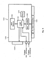
- a complete spatial light modulator apparatus in accordance with this invention also features DMD controller 80, Fig. 7 having digital input connector 100 connected to digital interface 104 of computer 106 via digital interface cable 102.
- Pattern generation subsystem 103 also operating on computer 106 and discussed in further detail below is configured to output pattern image data to digital interface 104 which provides a digital drive signal to DMD controller 80 via digital cable 102 corresponding to the pattern image data.
- DMD controller 80 in turn is connected to DMD 48 and drives the individual micromirrors of DMD 48 to generate the pattern image transmitted via optics 52 and 54, Figs. 2 and 6 , to microscope 38.
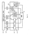
- digital interface 104, Fig. 7 is housed on PC card 120, Fig. 8 received in computer 106, Fig. 7 and has digital output connector 105 connected to digital cable 102, Fig. 7 .
- digital interface 104 includes clock 122 which provides a clock signal to logic device 124 (e.g., a field programmable gate array (FPGA)).
- logic device 124 is responsive to pattern image data provided by the pattern generation subsystem 103 via computer bus interface 180 and PC Card connection 181 and the clock signal and is configured to assign pixels to the pattern image data and to serialize the assigned pixels according to the clock signal to reformat the pattern image data to correspond to the spatial addressing of DMD 48.
- Logic device 124, Fig. 8 of digital interface 104 is also configured to generate a plurality of timing signals based on the clock signal to synchronize serialization of the assigned pixels.
- the plurality of timing signals correspond to DMD address counter signals but may be multiplied in frequency by logic device 124 to provide faster global dark resets of the mirrors of DMD 48, Fig. 7 .
- Logic device 124, Fig. 8 is preferably configured to provide a reset mirror command, switch to a new mirror state command, and a hold mirror state command to reset, new state, or hold all of the mirrors of DMD 48, Fig. 7 simultaneously.
- pattern generation subsystem 103 namely software operating on computer 106, is configured to output pattern image data to digital interface 104 which provides the digital drive signal on digital cable 102 to DMD controller 80 corresponding to the pattern image data.
- Pattern generation subsystem 103 provides a bitmapped mask image 170, Fig. 9 containing an informational mode header.
- Camera 56, Fig. 7 which is mounted on the microscope is connected via camera cable 150 to camera interface 152 located within computer 106.
- Camera interface 152 may be a frame grabber type card to interface to analog camera video signals, to digitize those signals into video data, and to distribute that data into the computer data bus.
- camera interface 152 is a digital device such as an IEEE 1394 interface to allow use of cameras compliant with the IEEE 1394 digital communications standard.
- each DMD 48 contains an array of several hundred thousand micromirrors on the surface.
- Each micromirror is typically 16 microns square and separated from each other by a 1 micron space.
- Each micromirror is addressable electronically. With a logic state of high in the SRAM beneath the micromirror, the micromirror tilts to a positive 10° position, typically, which herein is called the "on" state. With a logic state of low, the micromirror tilts to a negative 10° position, typically, which herein is called the "off” state.
- the light emitted from light source 46, Fig. 2 which is incident on the off state micromirrors of DMD 48 is reflected along an axis other than illumination axis 60 into light baffle 51.
- specimen 45 is somewhat reflective
- light source 46 is turned on and the micromirrors of DMD 48 representing the pattern "X" are in the "on” state.
- the image at eye point 63 is the image of specimen 45 superimposed on the image of the micromirror pattern "X" of DMD 48.
- the same image is present at camera 56 and at computer monitor 154, Fig. 7 . If objective 43, Fig. 2 of microscope 38 is changed to one of a higher magnification, the image of specimen 45 at the same locations will be larger but the pattern "X" image of the array of micromirrors of DMD 48 will not change in size at eye point 63.
- pixel is used in a variety of contexts.
- the manufacturer of DMD 48 calls each micromirror a pixel
- DMD 48 is said to break the light into a plurality of separate regions called pixels
- the digital video image of specimen 45 under microscope 38 is composed of pixels
- monitor 154 Fig. 7 is resolved into pixels.
- the spatial representation of each micromirror of DMD 48, Figs. 2 and 7 is called a DMD pixel
- the spatial representation of the image acquired by video camera 56 and viewed on computer monitor 154 is called a screen pixel.
- Software 103 controls DMD 48 by way of digital interface 104, digital interface cable 102 and DMD controller 80.
- Software 103, Fig. 11 displays on monitor 154 a live video image of the specimen captured by camera 56 transmitted over camera cable 150 to camera interface 152.
- the live video image of the specimen is displayed on monitor 154 for reference only in order to target what areas are to be masked.
- mouse 158 and the drawing editor 160 portion of software 103 the user has the ability to draw translucent mask-overlays of any desired shape which superimpose upon the image of the specimen. The user will still be able to see the live video image underneath the translucent mask overlay.
- the user will also be able to select from a set of pre-defined translucent mask-overlays (including full-field) or to select and recall user-defined translucent mask-overlays from stored computer files. The user can than select to have the specimen illuminated in a pattern identical to the shape of these overlays.
- Drawing editor 160 of pattern generation subsystem 103, Fig. 11 is responsive to keyboard 156, Fig. 7 or mouse 158 or any other input device for drawing a pattern shape.
- Alpha blending routine 162, Fig. 11 is responsive to camera 56, Fig. 7 (via camera interface 152) and drawing editor 160, Fig. 11 for representing the pattern drawn using drawing editor 160 translucently on the display or monitor 154 over the specimen image acquired by camera 56.
- digital interface 104, Fig. 7 is responsive to drawing editor 160, Fig. 11 to provide a digital drive signal which controls DMD 48, Fig. 7 via DMD controller 80 to generate a pattern mask image which represents the translucent pattern shape.
- Pattern generation subsystem 103 may further include a set of stored calibration values 166, Fig. 11 and a spatial scale and offset routine 168 interposed between drawing editor 160 and digital interface 104 to be responsive to the stored calibration values 166 for correlating the screen pixels of the drawn pattern shape to the pixels of DMD 48.
- drawing editor 160 Fig. 11 preferably generates data for the mask-overlay image to be displayed on monitor 154 and also combines that data with calibrated spatial scale and offset information via routine 168 and the calibration values stored at 166 to form a solid mask image to be transferred to DMD 48.
- the three images are separate sets of data, the specimen image is solid, the mask-overlay image is translucent and is overlayed upon the specimen image and thirdly, the mask image is solid, scaled, and offset.
- Scale and offset routine 168 in connection with calibration values 166, allows scaling and offset in two spatial axes, in order to achieve accurate and repeatable registration between screen pixels in the translucent mask-overlay and the DMD pixels.
- DMD pixels correspond optically to the spatial positions at specimen plane 39, Fig. 6 which correspond to camera pixels which correspond back to screen pixels on the live video image on monitor 154, Fig. 11 . In this way, targeting of the desired areas may be done in advance of the illumination sequence with accuracy. Calibration is not required on a frequent basis, but typically preformed only at the time of set-up of the system or upon changing optical subsystem 52, 54, Fig. 2 .
- Drawing editor 160, Fig. 11 data for the mask-overlay image are sent through alpha blending routine 162 to produce desired translucently and then displayed on monitor 154.
- Drawing editor 160 data is also sent through scale and offset routine 168 and then directed to digital interface 104 over the data bus of the computer.
- digital interface 104 incorporates logic device 124, Fig. 8 such as a field programmable gate array (FPGA).
- Digital interface 104 reformats the mask image data to correspond with the spatial addressing of DMD 48, Fig. 11 , creates timing and control sequences and provides the reformatted data and sequences to DMD controller 80 via digital interface cable 102.
- DMD controller 80, Fig. 10 buffers the mask image data and sequences, loads the memory cells of DMD 48, and provides additional control signals and voltages required by DMD 48.
- Software 103, Fig. 7 allows the user to control the timing of the illumination in a format such as with pull-down menus. Predetermined and user-defined timing schedules are available to the user. Automatic, manual, and externally triggered modes of operation are possible.
- drawing editor 160 Fig. 11 is used to draw a mask image
- scale and offset routine 168 processes that image according to the stored calibration values 166.
- This output to digital interface 104 is in the form of a bitmap image and added to the image may be an instructional mode header from software control module 165, Fig. 11 to designate the operational mode (single mask image, multiple repetitions of the image, "live" mode where the mask is generated as fast as possible while the user manipulates drawing editor 160) and information about how the mask image is to be produced such as start time, duration of mask (on time) internal or external trigger, and/or trigger out selection (for triggering the user's light source or detector).
- This block of data may be transferred over the computer PCI bus by a standard technique called direct memory access (DMA) 190, Fig. 9 to digital interface 104.
- DMA direct memory access
- the mask image could be in the form of vectorized data instead of bitmap data.
- the coordinates for the corners of a shape such as a square would transfer faster over DMA.
- logic device 124 of digital interface 104 would have the additional task of bitmapping the data to correspond with the DMD array and "OR"-ing that data to the RAM memory to over-write only the areas changed from the last frame.
- the serialization of data by the FPGA for output to the DMD controller would remain the same.
- Digital interface 104 Figs. 8 and 9 thus preferably has PC interface 180 which listens to the computer bus.
- the block of data flows through PC interface 180 and through logic device 124.
- Logic device 124 functions to strip off and retain the informational mode header, allowing the bitmap data to flow into random access memory (RAM) 182 as shown in Fig. 9 .
- Logic device 124 then uses clock 122 to generate the appropriate counter reset signals (timing generation) and synchronously reads bitmap data out of RAM 182 in a serial fashion; for example, 9600 bits long x 50 channels wide, consistent with the structure of the DMD addressing scheme.
- These data along with the timing signals are sent out over digital interface cable 102, Fig. 7 through DMD controller 80 and into the SRAM addresses on DMD 48.
- Fig. 8 issues a "Mirror drive command" which, when interpreted by DMD controller 80, Fig. 10 causes the micromirrors of the DMD 48 to reset, then read their new states from the DMD SRAM addresses, tilt to those new states, and hold until the next such command.
- the DMD At some time specified by the operator, through external trigger or software (duration), according to the mode, the DMD will be requested to go dark. The quicker the DMD can go dark again after displaying a mask, the better the performance in a situation requiring a brief pulse of light.
- the "Dark" is a global command line wired to the DMD through the DMD controller.
- the Dark command essentially writes logic state low to all of the RAM addresses on the DMD during a sequence of timing signals regardless of data input states. Since the addresses are selected by the timing signals, the effect is not instantaneous but normally distributed over 640 clock cycles.
- logic device 124 will issue a Dark sequence, logic device 124 will hold the Dark command high, and further generate specially compacted timing signals (compacted by a factor of four) to allow global addressing of the Dark command four times faster than normal.
- the logic device need not disturb the bitmap image in RAM memory 182 from the last mask image.
- logic device 124 functions as described above.
- logic device 124 will not enter the Dark sequence, but communicates with the software over bus interface 180 to indicate that an image has been sent to DMD controller 80, Fig. 7 and a Mirror drive command issued. This command instructs the software to begin another sequence of data block (bitmap image and header) transferred via DMA to digital interface 120, Fig. 8 . In this way, when the operator is drawing or moving a drawn shape with drawing editor 160, Fig. 11 , the mask will track those movements as fast as the system will allow with no dark frames in between.
- DMD controller 80 Figs. 10 is connected to digital interface cable 102 as discussed above and appropriately buffers the pattern image data 200 as shown at 210 along with the timing signals 202 and Dark signal and sends them to DMD 48. It also converts the Mirror drive command signals to the high voltage analog waveform as shown at 208 required to electrostatically tilt the mirrors of DMD 48.
- DMD 48 is further divided into fifteen groups of rows, each with its Mirror drive command line, all of these lines are actuated simultaneously for even illumination. Note that Texas Instruments, the manufacturer of the preferred DMD 48, activates these groups in sequence to take advantage of the writing of each column from top to bottom. The row group is written to, and then, while the next row group is being written to, the Mirror drive command for the first group is issued. This, however, results in the image being drawn in blocks from top to bottom whereas in the system of this invention the image appears all at once.
- DMD controller 80 also contains various voltage regulation and conversion function 206 to power DMD 48 and to select DMD 48 attributes by maintaining various DMD pins at certain voltages as shown at 212.
- the benefits of the present invention over the prior art are several and significant.
- the most evident advantage achieved is the ability to control and target the spatial distribution of illumination in a conventional microscope. Areas of the specimen to be illuminated can be very small - on the order of few microns - or the areas can be very large - on the order of hundreds of microns.
- Another major advantage of the present invention is the ability to customize the pattern of illumination which will be transmitted to the specimen in the microscope. This feature is of great benefit to researchers in the life sciences industry who need to illuminate or mask biological structures which are seldom geometric and uniform. By virtue of the ability to illuminate a specimen selectively, a researcher will be able to gain the ability to monitor and measure by photonic means select areas of the specimen with the same level of control.
- the present invention communicates directly with the DMD in a true black and white temporally-static manner unlike DMD projectors with standard pulse width modulated DMD interfaces. This eliminates any raster-type scanning of the mask pixels which reduce optical throughput and might adversely effect sensitive scientific experiments.
- the ability to customize the illumination of a microscope in real time using a translucent live-video interface is unique to the subject invention.
- the present invention provides an illumination system for a conventional microscope which gives the user both spatial and temporal control over specimen illumination.
- the array of programmable micromirrors is inserted in the illumination axis such that when activated they allow light to be reflected along the illumination axis to the specimen plane.
- Each micromirror directs light toward a spatial position of the specimen plane which corresponds to the spatial position of the micromirror in a conjugate plane.
- the innovative software developed and described above enables the user to select areas in the field of view to be illuminated, or conversely to be masked and not illuminated by a light source.
- the user is also able to control the timing of illumination, ranging from single pulses of varying length, to continuous illumination.
- a halogen light source 41, Fig. 2 may be used to transluminate from below a culture of living cells on the stage of a conventional microscope.
- Video camera 56 is mounted to the camera port of microscope 38 with the data output connected to the camera interface 152 of computer 106, Fig. 7 which displays the live-video image of the specimen on computer monitor 154.
- the researcher desires to illuminate, i.e., target, some of the cells in the field of view with a second light source and not other cells.
- the user draws translucent overlays on computer monitor 154 superimposed on but not obscuring the target cells.
- a light source 46 such as an arc lamp used for epifluorescence excitation which is made to illuminate DMD 48 by way of optical element 58.
- Patterned light will be directed into microscope 38 along illumination axis 60 and will shine down from above onto the specimen culture at specimen plane 39.
- the spatial position of the mask-overlays relative to the specimen image correspond to the spatial position of the micromirrors of the DMD.
- the user selects a time sequence and triggers the software.
- a spatial map of the overlays is encoded and directed to the DMD which reflects the light from light source 46 to the cell culture for a selected period of time.
Landscapes
- Physics & Mathematics (AREA)
- General Physics & Mathematics (AREA)
- Engineering & Computer Science (AREA)
- Chemical & Material Sciences (AREA)
- Analytical Chemistry (AREA)
- Optics & Photonics (AREA)
- Multimedia (AREA)
- Computer Hardware Design (AREA)
- Theoretical Computer Science (AREA)
- Computer Vision & Pattern Recognition (AREA)
- Microscoopes, Condenser (AREA)
Claims (14)
- Räumliche Lichtmodulatorvorrichtung für ein optisches Mikroskopsystem, wobei die Vorrichtung Folgendes umfasst:einen Optikkopf (30'), der Folgendes beinhaltet:einen Montageflansch (34) zum Montieren des Optikkopfes an einem Port des Mikroskops (38),eine DMD (48) zum Erzeugen eines Lichtbildmusters, eine Lichtquellenhalterung (44) zum Aufnehmen einer Beleuchtungsquelle (46,41), undein oder mehrere optische Elemente (52, 54, 58) zum Leiten von Licht von der Beleuchtungsquelle zur DMD und zum Leiten des von der DMD erzeugten Musterbildes auf das Mikroskop;eine DMD-Steuerung (88) mit einem digitalen Eingang, die mit der DMD zum Ansteuern der einzelnen Mikrospiegel der DMD verbunden ist, um das Musterbild zu erzeugen;ein Mustererzeugungssubsystem (103), das auf einem Computer betreibbare Software umfasst;und eine digitale Schnittstelle (104), die zwischen dem digitalen Eingang der DMD-Steuerung und dem Mustererzeugungssubsystem geschaltet ist, wobei die digitale Schnittstelle zum Senden eines digitalen Ansteuerungssignals zur DMD-Steuerung konfiguriert ist, das den Musterbilddaten entspricht, dadurch gekennzeichnet, dass das genannte Mustererzeugungssubsystem (103) einen Zeicheneditor (160) beinhaltet, wobei die genannte digitale Schnittstelle (104) auf den genannten Zeicheneditor anspricht um das genannte digitale Ansteuerungssignal bereitzustellen; so dassdas genannte Mustererzeugungssubsystem so konfiguriert ist, dass es einem Benutzer gestattet, Timing und räumliche Verteilung der von dem Lichtmusterbild bewirkten Beleuchtung zu steuern und entsprechende Musterbilddaten auszugeben, und wobei das genannte Mustererzeugungssubsystem (103) so konfiguriert ist, dass es dem genannten Benutzer gestattet, vorbestimmte und benutzerdefinierte Zeitpläne für die genannte Beleuchtung auszuwählen.
- Räumliche Lichtmodulatorvorrichtung nach Anspruch 1, wobei die genannten Ausgabemusterbilddaten eine Startzeit für das genannte Musterbild beinhalten.
- Räumliche Lichtmodulatorvorrichtung nach Anspruch 1 oder 2, wobei die genannten Ausgabemusterbilddaten eine Dauer für das genannte Musterbild beinhalten.
- Räumliche Lichtmodulatorvorrichtung nach einem der Ansprüche 1 bis 3, wobei die genannte Vorrichtung in einem extern ausgelösten Modus betrieben werden kann und die genannte digitale Schnittstelle (104) zum Empfangen eines externen Auslöseeingangs konfiguriert ist, wobei die genannte digitale Schnittstelle zum Senden des genannten digitalen Ansteuerungssignals zu der DMD-Steuerung (80) als Reaktion auf den genannten externen Auslöseeingang konfiguriert ist.
- Räumliche Lichtmodulatorvorrichtung nach einem der Ansprüche 1 bis 4, wobei die genannte Vorrichtung in einem manuell ausgelösten Modus betrieben werden kann, wobei das genannte Mustererzeugungssubsystem (103) so konfiguriert ist, dass es dem genannten Benutzer gestattet, die Implementation einer gewählten Beleuchtungszeitsequenz auszulösen.
- Räumliche Lichtmodulatorvorrichtung nach einem vorherigen Anspruch, wobei die genannten Ausgabemusterbilddaten ein Bitmap-Image und einen Modusheader (170) beinhalten, wobei der genannte Modusheader Informationen darüber beinhaltet, wie das genannte Musterbild zu erzeugen ist.
- Räumliche Lichtmodulatorvorrichtung nach Anspruch 1, die ferner einen Monitor (154) zum Anzeigen eines Live-Videobildes einer von einer Kamera (56) erfassten Probe beinhaltet, wobei der genannte Zeicheneditor auf ein Benutzereingabegerät (156, 158) anspricht und eine Musterform zum Legen einer transluszenten Überlagerungsmaske auf das genannte Videobild zeichnet, das der genannten Musterform entspricht, wobei die genannte digitale Schnittstelle (104) auf den genannten Zeicheneditor anspricht um das genannte digitale Ansteuerungssignal bereitzustellen, so dass das genannte Musterbild die Musterform der genannten transluszenten Überlagerungsmaske repräsentiert.
- Räumliche Lichtmodulatorvorrichtung nach Anspruch 1, wobei das genannte Mustererzeugungssubsystem (103) zum Bereitstellen einer Mehrzahl von vom Benutzer wählbaren vordefinierten transluszenten Überlagerungsmasken konfiguriert ist.
- Räumlicher Lichtmodulator nach Anspruch 7 oder 8, wobei das genannte Mustererzeugungssubsystem (103) eine Alphamischroutine (162) als Reaktion auf die genannte Kamera (56) und auf den genannten Zeicheneditor (160) aufweist, um ein Muster zu repräsentieren, das mit dem genannten Zeicheneditor transluszent auf dem genannten Monitor (154) über das genannte Probenbild gezeichnet wurde.
- Räumliche Lichtmodulatorvorrichtung nach einem vorherigen Anspruch, wobei die DMD-Steuerung (80) zum Puffern der Musterbilddaten und zum Laden der Speicherzellen der DMD (48) konfiguriert ist, wobei die DMD-Steuerung ferner zum Bereitstellen eines Rückstellbefehls, eines Zustandwechselbefehls und eines Haltebefehls zum Zurückstellen, Zustandwechseln bzw. Halten aller Mikrospiegel der DMD gleichzeitig konfiguriert ist.
- Räumliche Lichtmodulatorvorrichtung nach einem vorherigen Anspruch, wobei die genannte digitale Schnittstelle (104) eine Logiksteuerung (124) beinhaltet, die zum Bereitstellen eines Spiegelrückstellbefehls, eines Spiegelzustandwechselbefehls und eines Spiegelzustandhaltebefehls konfiguriert ist.
- Räumliche Lichtmodulatorvorrichtung nach Anspruch 11, wobei die genannte DMD-Steuerung (80) ferner so konfiguriert ist, dass sie als Reaktion auf die genannten Befehle bewirkt, dass die genannten Mikrospiegel sich zurückstellen, jeweilige neue Zustände aus den jeweiligen Speicherzellen lesen, auf die jeweiligen neuen Zustände kippe und sie halten, bis der nächste Befehl eingeht.
- Räumliche Lichtmodulatorvorrichtung nach Anspruch 1, wobei das genannte optische Mikroskop (38) eine Kamera (56) zum Abbilden einer durch das Mikroskop betrachteten Probe auf einem Display (154) beinhaltet, und wobei die genannte digitale Schnittstelle (104) auf den Zeicheneditor (160) anspricht um das genannte digitale Ansteuerungssignal zum Steuern der genannten DMD (48) bereitzustellen, um das genannte Musterbild mit einer mit einem auf dem Display gezeigten transluszenten Muster identischen Form zu erzeugen.
- Räumliche Lichtmodulatorvorrichtung nach Anspruch 1 oder 13, wobei das genannte Mustererzeugungssubsystem (103) ferner einen Satz von gespeicherten Kalibrationswerten und eine räumliche Skalen- und Versatzroutine (168) zwischen dem Zeicheneditor (160) und der digitalen Schnittstelle (104) aufweist, wobei die genannte Routine auf die genannten gespeicherten Kalibrationswerte zum Korrelieren von Pixeln einer Musterform anspricht, die mit dem genannten Zeicheneditor auf die Pixel der genannten DMD gezeichnet wurde.
Priority Applications (1)
| Application Number | Priority Date | Filing Date | Title |
|---|---|---|---|
| EP10011528A EP2293131A1 (de) | 2001-11-08 | 2002-07-25 | Räumliche Lichtmodulatorvorrichtung |
Applications Claiming Priority (5)
| Application Number | Priority Date | Filing Date | Title |
|---|---|---|---|
| US33780101P | 2001-11-08 | 2001-11-08 | |
| US337801P | 2001-11-08 | ||
| US10/191,947 US6885492B2 (en) | 2001-11-08 | 2002-07-09 | Spatial light modulator apparatus |
| US191947 | 2002-07-09 | ||
| PCT/US2002/023864 WO2003040798A1 (en) | 2001-11-08 | 2002-07-25 | Spatial light modulator apparatus |
Related Child Applications (1)
| Application Number | Title | Priority Date | Filing Date |
|---|---|---|---|
| EP10011528A Division-Into EP2293131A1 (de) | 2001-11-08 | 2002-07-25 | Räumliche Lichtmodulatorvorrichtung |
Publications (3)
| Publication Number | Publication Date |
|---|---|
| EP1442332A1 EP1442332A1 (de) | 2004-08-04 |
| EP1442332A4 EP1442332A4 (de) | 2008-05-28 |
| EP1442332B1 true EP1442332B1 (de) | 2014-07-16 |
Family
ID=26887568
Family Applications (2)
| Application Number | Title | Priority Date | Filing Date |
|---|---|---|---|
| EP02756709.8A Expired - Lifetime EP1442332B1 (de) | 2001-11-08 | 2002-07-25 | Räumliche lichtmodulatorvorrichtung |
| EP10011528A Withdrawn EP2293131A1 (de) | 2001-11-08 | 2002-07-25 | Räumliche Lichtmodulatorvorrichtung |
Family Applications After (1)
| Application Number | Title | Priority Date | Filing Date |
|---|---|---|---|
| EP10011528A Withdrawn EP2293131A1 (de) | 2001-11-08 | 2002-07-25 | Räumliche Lichtmodulatorvorrichtung |
Country Status (4)
| Country | Link |
|---|---|
| US (3) | US6885492B2 (de) |
| EP (2) | EP1442332B1 (de) |
| JP (1) | JP4084303B2 (de) |
| WO (1) | WO2003040798A1 (de) |
Families Citing this family (65)
| Publication number | Priority date | Publication date | Assignee | Title |
|---|---|---|---|---|
| US7391929B2 (en) * | 2000-02-11 | 2008-06-24 | Sony Corporation | Masking tool |
| US7019376B2 (en) * | 2000-08-11 | 2006-03-28 | Reflectivity, Inc | Micromirror array device with a small pitch size |
| US6885492B2 (en) | 2001-11-08 | 2005-04-26 | Imaginative Optics, Inc. | Spatial light modulator apparatus |
| US7623115B2 (en) * | 2002-07-27 | 2009-11-24 | Sony Computer Entertainment Inc. | Method and apparatus for light input device |
| JP2004309702A (ja) * | 2003-04-04 | 2004-11-04 | Olympus Corp | 顕微鏡 |
| WO2004104790A2 (en) | 2003-05-20 | 2004-12-02 | Kagutech Ltd. | Digital backplane |
| US20050219689A1 (en) * | 2004-03-31 | 2005-10-06 | Copeland David J | Microscope with retractable cord |
| US7463296B2 (en) * | 2004-04-01 | 2008-12-09 | Microsoft Corporation | Digital cameras with luminance correction |
| WO2006080023A1 (en) * | 2005-01-31 | 2006-08-03 | Cognitens Ltd. | Method and system for illumination adjustment |
| US7872050B2 (en) * | 2005-03-14 | 2011-01-18 | Yaupon Therapeutics Inc. | Stabilized compositions of volatile alkylating agents and methods of using thereof |
| US20080056723A1 (en) * | 2005-08-09 | 2008-03-06 | Randy Clinton Giles | Multiple access free space laser communication method and apparatus |
| ATE488780T1 (de) * | 2005-09-13 | 2010-12-15 | Univ Albert Ludwigs Freiburg | Mikroskopieverfahren mit räumlich modulierbarer beleuchtung |
| US20080151194A1 (en) * | 2006-01-31 | 2008-06-26 | Avner Segev | Method and System for Illumination Adjustment |
| CN101467089B (zh) * | 2006-04-10 | 2012-05-16 | 迈克罗拉布诊断有限公司 | 具有多个快门元件的成像装置 |
| US20090109518A1 (en) * | 2006-04-10 | 2009-04-30 | Mycrolab Diagnostics Pty Ltd | Imaging apparatus with a plurality of shutter elements |
| DE102006027836B4 (de) * | 2006-06-16 | 2020-02-20 | Carl Zeiss Microscopy Gmbh | Mikroskop mit Autofokuseinrichtung |
| DE102006034905B4 (de) * | 2006-07-28 | 2015-07-30 | Carl Zeiss Microscopy Gmbh | Anordnung zur Signalverarbeitung am Ausgang eines Mehrkanaldetektors |
| DE102008041821A1 (de) * | 2008-09-04 | 2010-03-11 | Leica Microsystems (Schweiz) Ag | Videoadapter für eine Mikroskopkamera |
| EP2315065B1 (de) * | 2009-10-26 | 2015-05-13 | Olympus Corporation | Mikroskop |
| JP5591007B2 (ja) * | 2009-11-20 | 2014-09-17 | オリンパス株式会社 | 顕微鏡装置 |
| US8532398B2 (en) * | 2010-03-26 | 2013-09-10 | General Electric Company | Methods and apparatus for optical segmentation of biological samples |
| US9389408B2 (en) * | 2010-07-23 | 2016-07-12 | Zeta Instruments, Inc. | 3D microscope and methods of measuring patterned substrates |
| US9207237B2 (en) | 2010-08-23 | 2015-12-08 | President And Fellows Of Harvard College | Systems, methods, and workflows for optogenetics analysis |
| CA2838330C (en) | 2010-08-23 | 2021-01-26 | President And Fellows Of Harvard College | Optogenetic probes for measuring membrane potential |
| EP3358387A1 (de) | 2010-08-27 | 2018-08-08 | The Board of Trustees of The Leland Stanford Junior University | Mikroskopiebildgebungsvorrichtung mit erweiterten bildgebungseigenschaften |
| JP5872862B2 (ja) * | 2010-11-29 | 2016-03-01 | アスカカンパニー株式会社 | 光照射装置及び顕微鏡 |
| US9069175B2 (en) | 2011-04-08 | 2015-06-30 | Kairos Instruments, Llc | Adaptive phase contrast microscope |
| DE112012005960T5 (de) * | 2012-02-29 | 2014-11-06 | Agilent Technologies, Inc. | Softwaredefiniertes Mikroskop |
| US20140368904A1 (en) * | 2012-02-29 | 2014-12-18 | Agilent Technologies, Inc. | Software Defined Microscope |
| US9642606B2 (en) | 2012-06-27 | 2017-05-09 | Camplex, Inc. | Surgical visualization system |
| US9629523B2 (en) | 2012-06-27 | 2017-04-25 | Camplex, Inc. | Binocular viewing assembly for a surgical visualization system |
| US9323039B2 (en) | 2012-11-06 | 2016-04-26 | Industrial Technology Research Institute | Particle manipulation system and projection device |
| DE102012111452B3 (de) * | 2012-11-27 | 2014-03-20 | Karlsruher Institut für Technologie | Optische Anordnung, ihre Verwendung und Verfahren zur Aufnahme eines Bildes |
| JP6128822B2 (ja) * | 2012-12-05 | 2017-05-17 | オリンパス株式会社 | 光学装置 |
| JP6150586B2 (ja) * | 2013-03-29 | 2017-06-21 | オリンパス株式会社 | 顕微鏡 |
| EP2999414B1 (de) | 2013-05-21 | 2018-08-08 | Camplex, Inc. | Chirurgische visualisierungssysteme |
| WO2015042483A2 (en) | 2013-09-20 | 2015-03-26 | Camplex, Inc. | Surgical visualization systems |
| EP3047326A4 (de) * | 2013-09-20 | 2017-09-06 | Camplex, Inc. | Chirurgische visualisierungssysteme und anzeigen |
| JP6211389B2 (ja) * | 2013-10-25 | 2017-10-11 | 株式会社キーエンス | 顕微鏡装置 |
| JP6327830B2 (ja) * | 2013-10-25 | 2018-05-23 | 株式会社キーエンス | 顕微鏡撮像装置、顕微鏡撮像方法および顕微鏡撮像プログラム |
| JP6305012B2 (ja) * | 2013-10-25 | 2018-04-04 | 株式会社キーエンス | 顕微鏡撮像装置、顕微鏡撮像方法および顕微鏡撮像プログラム |
| JP6266302B2 (ja) * | 2013-10-25 | 2018-01-24 | 株式会社キーエンス | 顕微鏡撮像装置、顕微鏡撮像方法および顕微鏡撮像プログラム |
| EP3095004A4 (de) | 2014-01-14 | 2017-09-20 | Applied Scientific Instrumentation, Inc. | Lichtfoliengenerator |
| CA2879598A1 (en) | 2014-01-26 | 2015-07-26 | Matthew S. Muller | Periodic fringe imaging with structured pattern illumination and electronic rolling shutter detection |
| US20150301030A1 (en) | 2014-04-22 | 2015-10-22 | Q-State Biosciences, Inc. | Models for parkinson's disease studies |
| CA2947771C (en) | 2014-06-18 | 2025-11-18 | President And Fellows Of Harvard College | OPTOGENETIC PROBES TO MEASURE MEMBRANE POTENTIAL |
| EP3226799A4 (de) | 2014-12-05 | 2018-07-25 | Camplex, Inc. | Chirurgische visualisierungssysteme und anzeigen |
| WO2016115333A1 (en) | 2015-01-15 | 2016-07-21 | President And Fellows Of Harvard College | Optical selection of cells |
| US10048275B2 (en) | 2015-03-13 | 2018-08-14 | Q-State Biosciences, Inc. | Cardiotoxicity screening methods |
| US11154378B2 (en) | 2015-03-25 | 2021-10-26 | Camplex, Inc. | Surgical visualization systems and displays |
| WO2016187543A1 (en) | 2015-05-21 | 2016-11-24 | Q-State Biosciences, Inc. | Optogenetics microscope |
| EP3121637B1 (de) * | 2015-07-24 | 2021-09-01 | Leica Instruments (Singapore) Pte. Ltd. | Mikroskop und verfahren zum erzeugen eines kombinierten bildes aus mehreren einzelbildern eines objekts |
| EP3383247A4 (de) | 2015-11-25 | 2019-06-26 | Camplex, Inc. | Chirurgische visualisierungssysteme und anzeigen |
| KR101911869B1 (ko) | 2017-02-20 | 2018-10-30 | 한국과학기술원 | 광 감응성입자가 도포된 세포배양기판을 이용하여 국소적 신경활성 억제를 위한 광 패턴 조사 시스템 및 조사 방법 |
| KR101965951B1 (ko) * | 2017-04-06 | 2019-04-05 | 연세대학교 산학협력단 | 현미경 겸용 광 처리 장치 및 이를 이용하는 광 처리 방법 |
| DE102017109456A1 (de) | 2017-05-03 | 2018-11-08 | Carl Zeiss Microscopy Gmbh | Mikroskopsystem und Verfahren zum Betreiben eines Mikroskopsystems |
| US10918455B2 (en) | 2017-05-08 | 2021-02-16 | Camplex, Inc. | Variable light source |
| US10634618B2 (en) * | 2018-01-23 | 2020-04-28 | Hong Kong Applied Science and Technology Research Institute Company Limited | Apparatus and a method for inspecting a light transmissible optical component |
| KR20210121016A (ko) | 2018-12-21 | 2021-10-07 | 나노스트링 테크놀로지스, 인크. | 병리학적 표본의 모바일 디지털 공간 프로파일링을 위한 방법, 장치, 시스템 및 디바이스 |
| DE112019007543T5 (de) * | 2019-07-16 | 2022-03-31 | Haag-Streit Ag | Ophthalmologisches Spaltlampenmikroskop mit einem räumlichen Lichtmodulator |
| WO2021022360A1 (en) | 2019-08-08 | 2021-02-11 | Institut National D'optique | Systems and methods for optogenetic activation and monitoring |
| CA3153886A1 (en) | 2019-10-18 | 2021-04-22 | Nanostring Technologies, Inc. | Systems and methods for spatial mapping of expression profiling |
| US11741730B2 (en) * | 2021-06-24 | 2023-08-29 | Fei Company | Charged particle microscope scan masking for three-dimensional reconstruction |
| CN114018926B (zh) * | 2022-01-04 | 2022-03-22 | 天津大学四川创新研究院 | 一种基于灰阶的数字微镜调光模板制作方法 |
| CN117233947B (zh) * | 2023-11-15 | 2024-02-02 | 睿励科学仪器(上海)有限公司 | 显微镜照明系统、控制方法及显微成像检测系统 |
Citations (1)
| Publication number | Priority date | Publication date | Assignee | Title |
|---|---|---|---|---|
| US6243197B1 (en) * | 1996-10-25 | 2001-06-05 | Leica Mikroskopie Und Systeme Gmbh | Lighting device for a microscope |
Family Cites Families (29)
| Publication number | Priority date | Publication date | Assignee | Title |
|---|---|---|---|---|
| US4561731A (en) | 1980-03-10 | 1985-12-31 | Kley Victor B | Electronic illumination control |
| US5061049A (en) | 1984-08-31 | 1991-10-29 | Texas Instruments Incorporated | Spatial light modulator and method |
| US5083857A (en) | 1990-06-29 | 1992-01-28 | Texas Instruments Incorporated | Multi-level deformable mirror device |
| US5307056A (en) * | 1991-09-06 | 1994-04-26 | Texas Instruments Incorporated | Dynamic memory allocation for frame buffer for spatial light modulator |
| US5587832A (en) | 1993-10-20 | 1996-12-24 | Biophysica Technologies, Inc. | Spatially light modulated confocal microscope and method |
| US5923466A (en) | 1993-10-20 | 1999-07-13 | Biophysica Technologies, Inc. | Light modulated confocal optical instruments and method |
| US5583688A (en) * | 1993-12-21 | 1996-12-10 | Texas Instruments Incorporated | Multi-level digital micromirror device |
| US6107979A (en) * | 1995-01-17 | 2000-08-22 | Texas Instruments Incorporated | Monolithic programmable format pixel array |
| US5535047A (en) | 1995-04-18 | 1996-07-09 | Texas Instruments Incorporated | Active yoke hidden hinge digital micromirror device |
| US5999306A (en) | 1995-12-01 | 1999-12-07 | Seiko Epson Corporation | Method of manufacturing spatial light modulator and electronic device employing it |
| US5932119A (en) | 1996-01-05 | 1999-08-03 | Lazare Kaplan International, Inc. | Laser marking system |
| GB9603788D0 (en) | 1996-02-22 | 1996-04-24 | Isis Innovation | Confocal microscope |
| WO1997034171A2 (en) | 1996-02-28 | 1997-09-18 | Johnson Kenneth C | Microlens scanner for microlithography and wide-field confocal microscopy |
| US7144119B2 (en) | 1996-04-25 | 2006-12-05 | Bioarray Solutions Ltd. | System and method for programmable illumination pattern generation |
| US6038067A (en) | 1996-05-23 | 2000-03-14 | The Regents Of The University Of California | Scanning computed confocal imager |
| US5986781A (en) | 1996-10-28 | 1999-11-16 | Pacific Holographics, Inc. | Apparatus and method for generating diffractive element using liquid crystal display |
| US5923036A (en) | 1997-02-11 | 1999-07-13 | Bruker Instruments, Inc. | Spatially-multiplexed imaging microscope |
| US6177980B1 (en) | 1997-02-20 | 2001-01-23 | Kenneth C. Johnson | High-throughput, maskless lithography system |
| US5933274A (en) | 1997-05-15 | 1999-08-03 | Andrew F. DeSimone | Dye laser system |
| EP0911667B1 (de) * | 1997-10-22 | 2003-04-02 | Max-Planck-Gesellschaft zur Förderung der Wissenschaften e.V. | Programmierbares räumlich lichtmoduliertes Mikroskop und Mikroskopieverfahren |
| ATE272224T1 (de) | 1997-11-17 | 2004-08-15 | Max Planck Gesellschaft | Konfokales spektroskopiesystem und -verfahren |
| JPH11326826A (ja) | 1998-05-13 | 1999-11-26 | Sony Corp | 照明方法及び照明装置 |
| AU4333799A (en) | 1998-06-04 | 1999-12-20 | Board Of Regents, The University Of Texas System | Digital optical chemistry micromirror imager |
| US6215586B1 (en) | 1999-05-25 | 2001-04-10 | R.K.C. Technologies Inc. | Active optical image enhancer for a microscope |
| JP4531895B2 (ja) | 1999-12-06 | 2010-08-25 | オリンパス株式会社 | レーザ集光光学系及びそれを用いたレーザ走査型顕微鏡 |
| US20010033322A1 (en) * | 2000-01-21 | 2001-10-25 | Bommersbach William M. | Image data control unit for SLM-based photofinishing system |
| DE10018256A1 (de) | 2000-04-13 | 2001-10-25 | Leica Microsystems | Doppelkonfokales Rastermikroskop |
| AU2001289914A1 (en) * | 2000-09-25 | 2002-04-02 | Sensovation Ag | Image sensor device, apparatus and method for optical measurements |
| US6885492B2 (en) | 2001-11-08 | 2005-04-26 | Imaginative Optics, Inc. | Spatial light modulator apparatus |
-
2002
- 2002-07-09 US US10/191,947 patent/US6885492B2/en not_active Expired - Lifetime
- 2002-07-25 JP JP2003542378A patent/JP4084303B2/ja not_active Expired - Lifetime
- 2002-07-25 EP EP02756709.8A patent/EP1442332B1/de not_active Expired - Lifetime
- 2002-07-25 WO PCT/US2002/023864 patent/WO2003040798A1/en not_active Ceased
- 2002-07-25 EP EP10011528A patent/EP2293131A1/de not_active Withdrawn
-
2004
- 2004-11-17 US US10/991,256 patent/US7034983B2/en not_active Expired - Lifetime
-
2005
- 2005-05-26 US US11/137,953 patent/US6972892B2/en not_active Expired - Lifetime
Patent Citations (1)
| Publication number | Priority date | Publication date | Assignee | Title |
|---|---|---|---|---|
| US6243197B1 (en) * | 1996-10-25 | 2001-06-05 | Leica Mikroskopie Und Systeme Gmbh | Lighting device for a microscope |
Non-Patent Citations (1)
| Title |
|---|
| "PANELLINK A/V: THE DIGITAL SOLUTION FOR HDTV WHITE PAPER", PAPER SILICON IMAGE, 1 February 2001 (2001-02-01), pages 1 - 15, XP002948300 * |
Also Published As
| Publication number | Publication date |
|---|---|
| WO2003040798A1 (en) | 2003-05-15 |
| EP1442332A4 (de) | 2008-05-28 |
| US7034983B2 (en) | 2006-04-25 |
| US20030086145A1 (en) | 2003-05-08 |
| EP2293131A1 (de) | 2011-03-09 |
| JP2005508521A (ja) | 2005-03-31 |
| EP1442332A1 (de) | 2004-08-04 |
| JP4084303B2 (ja) | 2008-04-30 |
| US20050068607A1 (en) | 2005-03-31 |
| US20050213188A1 (en) | 2005-09-29 |
| US6885492B2 (en) | 2005-04-26 |
| US6972892B2 (en) | 2005-12-06 |
Similar Documents
| Publication | Publication Date | Title |
|---|---|---|
| EP1442332B1 (de) | Räumliche lichtmodulatorvorrichtung | |
| EP0547601B1 (de) | Farbanzeigevorrichtung unter Verwendung räumlichen Modulatoren | |
| US6898004B2 (en) | Microscope system | |
| US5633755A (en) | Projection apparatus and method | |
| US6591022B2 (en) | Illumination system for scrolling color recycling | |
| CN102245081B (zh) | 用于视觉刺激的高精度对比率显示器 | |
| US5943118A (en) | Arrangement and method for illumination in a stereoscopic ophthalmic microscope | |
| US6614031B2 (en) | Method for examining a specimen, and confocal scanning microscope | |
| US20030002040A1 (en) | Light modulated microarray reader and methods relating thereto | |
| US5319490A (en) | Helmet mounted display including synchronously moving tilted mechanisms | |
| US20060157638A1 (en) | Scanning microscope and specimen image obtaining method | |
| CN116897309A (zh) | 数字显微镜和操作数字显微镜的方法 | |
| JP2004191839A (ja) | プロジェクタ | |
| JP2008292578A (ja) | 顕微鏡用コントローラと、これを有する顕微鏡装置 | |
| JP2002055307A (ja) | Dmdを用いたカラー投影画像表示装置 | |
| JP2002149090A (ja) | 表示装置 | |
| US20050269523A1 (en) | Light modulated microarray reader and methods relating thereto | |
| CN114577762A (zh) | 一种基于数字微反射镜的数字共聚焦成像系统及方法 | |
| Dunn et al. | Properties of the DMD digital micromirror device for new emerging applications in optical engineering | |
| CN117666123A (zh) | 像源组件、显示装置和交通工具 | |
| JPH07154722A (ja) | 画像表示装置 | |
| Steele et al. | Performance of laser-addressed liquid crystal map overlay display | |
| JPH08262565A (ja) | 画像投影装置 | |
| JP2006030280A (ja) | 顕微鏡用照明装置、方法およびコンピュータプログラム | |
| JPH11295630A (ja) | 画像表示装置、および画像描画装置 |
Legal Events
| Date | Code | Title | Description |
|---|---|---|---|
| PUAI | Public reference made under article 153(3) epc to a published international application that has entered the european phase |
Free format text: ORIGINAL CODE: 0009012 |
|
| 17P | Request for examination filed |
Effective date: 20040408 |
|
| AK | Designated contracting states |
Kind code of ref document: A1 Designated state(s): AT BE BG CH CY CZ DE DK EE ES FI FR GB GR IE IT LI LU MC NL PT SE SK TR |
|
| AX | Request for extension of the european patent |
Extension state: AL LT LV MK RO SI |
|
| A4 | Supplementary search report drawn up and despatched |
Effective date: 20080429 |
|
| 17Q | First examination report despatched |
Effective date: 20080617 |
|
| RAP1 | Party data changed (applicant data changed or rights of an application transferred) |
Owner name: ANDOR TECHNOLOGY PLC |
|
| REG | Reference to a national code |
Ref country code: DE Ref legal event code: R079 Ref document number: 60246441 Country of ref document: DE Free format text: PREVIOUS MAIN CLASS: G02B0021060000 Ipc: G02B0021080000 |
|
| GRAP | Despatch of communication of intention to grant a patent |
Free format text: ORIGINAL CODE: EPIDOSNIGR1 |
|
| RIC1 | Information provided on ipc code assigned before grant |
Ipc: G02B 21/08 20060101AFI20140205BHEP Ipc: G01N 21/64 20060101ALI20140205BHEP Ipc: G02B 21/06 20060101ALI20140205BHEP Ipc: G02B 21/36 20060101ALI20140205BHEP Ipc: G09G 3/34 20060101ALI20140205BHEP |
|
| INTG | Intention to grant announced |
Effective date: 20140227 |
|
| GRAS | Grant fee paid |
Free format text: ORIGINAL CODE: EPIDOSNIGR3 |
|
| GRAA | (expected) grant |
Free format text: ORIGINAL CODE: 0009210 |
|
| RAP1 | Party data changed (applicant data changed or rights of an application transferred) |
Owner name: ANDOR TECHNOLOGY LIMITED |
|
| AK | Designated contracting states |
Kind code of ref document: B1 Designated state(s): AT BE BG CH CY CZ DE DK EE ES FI FR GB GR IE IT LI LU MC NL PT SE SK TR |
|
| REG | Reference to a national code |
Ref country code: GB Ref legal event code: FG4D |
|
| REG | Reference to a national code |
Ref country code: CH Ref legal event code: EP |
|
| REG | Reference to a national code |
Ref country code: IE Ref legal event code: FG4D |
|
| REG | Reference to a national code |
Ref country code: AT Ref legal event code: REF Ref document number: 677968 Country of ref document: AT Kind code of ref document: T Effective date: 20140815 Ref country code: CH Ref legal event code: NV Representative=s name: E. BLUM AND CO. AG PATENT- UND MARKENANWAELTE , CH |
|
| REG | Reference to a national code |
Ref country code: DE Ref legal event code: R096 Ref document number: 60246441 Country of ref document: DE Effective date: 20140821 |
|
| REG | Reference to a national code |
Ref country code: NL Ref legal event code: VDEP Effective date: 20140716 |
|
| REG | Reference to a national code |
Ref country code: AT Ref legal event code: MK05 Ref document number: 677968 Country of ref document: AT Kind code of ref document: T Effective date: 20140716 |
|
| PG25 | Lapsed in a contracting state [announced via postgrant information from national office to epo] |
Ref country code: BG Free format text: LAPSE BECAUSE OF FAILURE TO SUBMIT A TRANSLATION OF THE DESCRIPTION OR TO PAY THE FEE WITHIN THE PRESCRIBED TIME-LIMIT Effective date: 20141016 Ref country code: GR Free format text: LAPSE BECAUSE OF FAILURE TO SUBMIT A TRANSLATION OF THE DESCRIPTION OR TO PAY THE FEE WITHIN THE PRESCRIBED TIME-LIMIT Effective date: 20141017 Ref country code: FI Free format text: LAPSE BECAUSE OF FAILURE TO SUBMIT A TRANSLATION OF THE DESCRIPTION OR TO PAY THE FEE WITHIN THE PRESCRIBED TIME-LIMIT Effective date: 20140716 Ref country code: ES Free format text: LAPSE BECAUSE OF FAILURE TO SUBMIT A TRANSLATION OF THE DESCRIPTION OR TO PAY THE FEE WITHIN THE PRESCRIBED TIME-LIMIT Effective date: 20140716 Ref country code: SE Free format text: LAPSE BECAUSE OF FAILURE TO SUBMIT A TRANSLATION OF THE DESCRIPTION OR TO PAY THE FEE WITHIN THE PRESCRIBED TIME-LIMIT Effective date: 20140716 Ref country code: PT Free format text: LAPSE BECAUSE OF FAILURE TO SUBMIT A TRANSLATION OF THE DESCRIPTION OR TO PAY THE FEE WITHIN THE PRESCRIBED TIME-LIMIT Effective date: 20141117 |
|
| PG25 | Lapsed in a contracting state [announced via postgrant information from national office to epo] |
Ref country code: NL Free format text: LAPSE BECAUSE OF FAILURE TO SUBMIT A TRANSLATION OF THE DESCRIPTION OR TO PAY THE FEE WITHIN THE PRESCRIBED TIME-LIMIT Effective date: 20140716 Ref country code: CY Free format text: LAPSE BECAUSE OF FAILURE TO SUBMIT A TRANSLATION OF THE DESCRIPTION OR TO PAY THE FEE WITHIN THE PRESCRIBED TIME-LIMIT Effective date: 20140716 Ref country code: AT Free format text: LAPSE BECAUSE OF FAILURE TO SUBMIT A TRANSLATION OF THE DESCRIPTION OR TO PAY THE FEE WITHIN THE PRESCRIBED TIME-LIMIT Effective date: 20140716 |
|
| REG | Reference to a national code |
Ref country code: DE Ref legal event code: R097 Ref document number: 60246441 Country of ref document: DE |
|
| REG | Reference to a national code |
Ref country code: IE Ref legal event code: MM4A |
|
| PG25 | Lapsed in a contracting state [announced via postgrant information from national office to epo] |
Ref country code: IT Free format text: LAPSE BECAUSE OF FAILURE TO SUBMIT A TRANSLATION OF THE DESCRIPTION OR TO PAY THE FEE WITHIN THE PRESCRIBED TIME-LIMIT Effective date: 20140716 Ref country code: DK Free format text: LAPSE BECAUSE OF FAILURE TO SUBMIT A TRANSLATION OF THE DESCRIPTION OR TO PAY THE FEE WITHIN THE PRESCRIBED TIME-LIMIT Effective date: 20140716 Ref country code: MC Free format text: LAPSE BECAUSE OF FAILURE TO SUBMIT A TRANSLATION OF THE DESCRIPTION OR TO PAY THE FEE WITHIN THE PRESCRIBED TIME-LIMIT Effective date: 20140716 Ref country code: CZ Free format text: LAPSE BECAUSE OF FAILURE TO SUBMIT A TRANSLATION OF THE DESCRIPTION OR TO PAY THE FEE WITHIN THE PRESCRIBED TIME-LIMIT Effective date: 20140716 Ref country code: EE Free format text: LAPSE BECAUSE OF FAILURE TO SUBMIT A TRANSLATION OF THE DESCRIPTION OR TO PAY THE FEE WITHIN THE PRESCRIBED TIME-LIMIT Effective date: 20140716 Ref country code: SK Free format text: LAPSE BECAUSE OF FAILURE TO SUBMIT A TRANSLATION OF THE DESCRIPTION OR TO PAY THE FEE WITHIN THE PRESCRIBED TIME-LIMIT Effective date: 20140716 |
|
| PLBE | No opposition filed within time limit |
Free format text: ORIGINAL CODE: 0009261 |
|
| STAA | Information on the status of an ep patent application or granted ep patent |
Free format text: STATUS: NO OPPOSITION FILED WITHIN TIME LIMIT |
|
| 26N | No opposition filed |
Effective date: 20150417 |
|
| REG | Reference to a national code |
Ref country code: FR Ref legal event code: PLFP Year of fee payment: 14 |
|
| PG25 | Lapsed in a contracting state [announced via postgrant information from national office to epo] |
Ref country code: IE Free format text: LAPSE BECAUSE OF NON-PAYMENT OF DUE FEES Effective date: 20140725 |
|
| REG | Reference to a national code |
Ref country code: FR Ref legal event code: PLFP Year of fee payment: 15 |
|
| PG25 | Lapsed in a contracting state [announced via postgrant information from national office to epo] |
Ref country code: TR Free format text: LAPSE BECAUSE OF FAILURE TO SUBMIT A TRANSLATION OF THE DESCRIPTION OR TO PAY THE FEE WITHIN THE PRESCRIBED TIME-LIMIT Effective date: 20140716 Ref country code: BE Free format text: LAPSE BECAUSE OF FAILURE TO SUBMIT A TRANSLATION OF THE DESCRIPTION OR TO PAY THE FEE WITHIN THE PRESCRIBED TIME-LIMIT Effective date: 20140716 Ref country code: LU Free format text: LAPSE BECAUSE OF NON-PAYMENT OF DUE FEES Effective date: 20140725 |
|
| REG | Reference to a national code |
Ref country code: FR Ref legal event code: PLFP Year of fee payment: 16 |
|
| REG | Reference to a national code |
Ref country code: FR Ref legal event code: PLFP Year of fee payment: 17 |
|
| PGFP | Annual fee paid to national office [announced via postgrant information from national office to epo] |
Ref country code: GB Payment date: 20210610 Year of fee payment: 20 |
|
| PGFP | Annual fee paid to national office [announced via postgrant information from national office to epo] |
Ref country code: FR Payment date: 20210727 Year of fee payment: 20 |
|
| PGFP | Annual fee paid to national office [announced via postgrant information from national office to epo] |
Ref country code: DE Payment date: 20210721 Year of fee payment: 20 Ref country code: CH Payment date: 20210721 Year of fee payment: 20 |
|
| REG | Reference to a national code |
Ref country code: DE Ref legal event code: R071 Ref document number: 60246441 Country of ref document: DE |
|
| REG | Reference to a national code |
Ref country code: CH Ref legal event code: PL |
|
| REG | Reference to a national code |
Ref country code: GB Ref legal event code: PE20 Expiry date: 20220724 |
|
| PG25 | Lapsed in a contracting state [announced via postgrant information from national office to epo] |
Ref country code: GB Free format text: LAPSE BECAUSE OF EXPIRATION OF PROTECTION Effective date: 20220724 |