EP1443169A2 - Verstärkungselement zur Anordnung zwischen zwei Kunststoffprofilen benachbarter Blendrahmen - Google Patents
Verstärkungselement zur Anordnung zwischen zwei Kunststoffprofilen benachbarter Blendrahmen Download PDFInfo
- Publication number
- EP1443169A2 EP1443169A2 EP04001550A EP04001550A EP1443169A2 EP 1443169 A2 EP1443169 A2 EP 1443169A2 EP 04001550 A EP04001550 A EP 04001550A EP 04001550 A EP04001550 A EP 04001550A EP 1443169 A2 EP1443169 A2 EP 1443169A2
- Authority
- EP
- European Patent Office
- Prior art keywords
- web
- reinforcing element
- element according
- cover strip
- foot
- Prior art date
- Legal status (The legal status is an assumption and is not a legal conclusion. Google has not performed a legal analysis and makes no representation as to the accuracy of the status listed.)
- Granted
Links
- 230000003014 reinforcing effect Effects 0.000 title claims description 47
- 238000007789 sealing Methods 0.000 claims description 16
- 239000002184 metal Substances 0.000 claims description 6
- 230000002787 reinforcement Effects 0.000 claims description 5
- 238000005728 strengthening Methods 0.000 abstract 1
- 210000002414 leg Anatomy 0.000 description 17
- 238000009413 insulation Methods 0.000 description 4
- 238000004519 manufacturing process Methods 0.000 description 3
- 238000005553 drilling Methods 0.000 description 2
- 239000012212 insulator Substances 0.000 description 2
- 238000010276 construction Methods 0.000 description 1
- 230000008878 coupling Effects 0.000 description 1
- 238000010168 coupling process Methods 0.000 description 1
- 238000005859 coupling reaction Methods 0.000 description 1
- 238000007373 indentation Methods 0.000 description 1
- 238000009434 installation Methods 0.000 description 1
- 230000035515 penetration Effects 0.000 description 1
- 230000008092 positive effect Effects 0.000 description 1
- 230000005855 radiation Effects 0.000 description 1
- 210000000689 upper leg Anatomy 0.000 description 1
Images


Classifications
-
- E—FIXED CONSTRUCTIONS
- E06—DOORS, WINDOWS, SHUTTERS, OR ROLLER BLINDS IN GENERAL; LADDERS
- E06B—FIXED OR MOVABLE CLOSURES FOR OPENINGS IN BUILDINGS, VEHICLES, FENCES OR LIKE ENCLOSURES IN GENERAL, e.g. DOORS, WINDOWS, BLINDS, GATES
- E06B1/00—Border constructions of openings in walls, floors, or ceilings; Frames to be rigidly mounted in such openings
- E06B1/56—Fastening frames to the border of openings or to similar contiguous frames
- E06B1/60—Fastening frames to the border of openings or to similar contiguous frames by mechanical means, e.g. anchoring means
- E06B1/6007—Fastening frames to the border of openings or to similar contiguous frames by mechanical means, e.g. anchoring means between similar contiguous frames
Definitions
- the invention relates to a reinforcing element for Arrangement between two plastic profiles adjacent Frame, in particular of plastic windows and / or - Doors that extend the entire length of the plastic profiles extends and a receptacle on each long side non-positive fixing of a fastening web Has a cover strip.
- sheet metal Reinforcing element known, one on each long side Recording for the non-positive fixing of a fastening web has a cover strip, with between the recordings are parallel to each other Extend webs.
- the symmetrical reinforcing element lateral contact legs which are approximately in the middle Extend the area of the recordings outwards.
- This reinforcing element has good thermal conductivity because the heat transfer over the directly lying, the metal connecting webs takes place.
- it is necessary for plastic profiles different dimensions differently dimensioned Provide reinforcing elements because of the clear width between the stop legs on a certain plastic profile is coordinated.
- DE 198 55 966 A1 also discloses a reinforcing element for window frames, facades or the like with one inner part extending to the inside of the frame and an outer part extending to the outside of the frame, the two parts being thermally separated.
- one of the parts is made of metal and the other than Insulator manufactured and another thermal insulator connects the inner and the outer part.
- This multi-part reinforcement element is in its manufacture complex and therefore expensive.
- the object is achieved by a cross section T-shaped design of the reinforcing element, the foot and the bridge are each centered with the receptacle are provided for the fastening strip of the cover strip.
- the reinforcing element is in the Connection with all plastic profiles common in window construction to use because the foot or the bridge over the inside or outside of the plastic profile of the Frame can protrude and covered by the cover strip is.
- the foot is preferably 180 ° on each of its long sides flared to the outside and has a V-shaped cross section Entry slope for the fastening web.
- the foot is expediently on each of his Long sides flanged inwards by 180 °.
- the receptacle assigned to the foot preferably widens for the cover strip to a chamber in the web.
- the one with air filled chamber has a positive effect on the thermal insulation Properties of the reinforcing element.
- the chamber is an advantageous embodiment of the invention divided by a constriction of the web, the the Chamber section facing away from the foot for receiving at least one bracket to be fastened on the building side.
- the Inclusion of a bracket to be arranged above and below the chamber section can be positively or non-positively and ensures high stability of the two neighboring ones Frame, which, as usual, screwed together become.
- the one assigned to the web is expedient U-shaped receptacle for the cover strip, the two legs of the receptacle parallel to the outer contour of the web and the connecting leg Bridge the chamber.
- the foot and the are preferred Bridge made in one piece from sheet metal.
- the one-piece Manufacturing can take place, for example, by roll forming.
- Each frame is advantageously a frame on the long side facing the fastening web with a Provide recess for receiving sealing strips.
- the sealing strips are expediently used as sealing lips formed, which are arranged in the recess, that it is covered by the cover strip on the respectively assigned Place the plastic profile in a sealing position.
- the web expediently carries in hollow chambers insulation elements protruding from the plastic profiles.
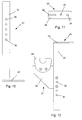
- the flange plate is provided with holes for fastening on the building side and the angle leg is on the end face in the chamber section extends.
- the angle leg of the bracket with a 2-dimensionally adjustable Provide bracket for receiving a roller shutter shaft.
- the Bracket formed in this way becomes the upper fastening of the reinforcing element uses and avoids the building side Arrangement of additional bearings for roller shutter shafts, the bracket both in height and in the Depth is adjustable.
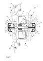
- the reinforcing element 1 is between two plastic profiles Adjacent frame 3 arranged.
- Each of the Plastic profiles 2 is extending in the longitudinal direction Provide hollow chambers 4 and has a seal 5th on that as a stop for a sash frame, not shown serves.
- the cross section of the reinforcing element 1 is T-shaped a foot 8 and a web 9 formed, which are in one piece are made of a metal sheet.
- the foot 8 each of its long sides 10 flanged inwards by 180 °.
- the foot 8 is on each of its long sides 10 flared by 180 ° to the outside and one facing outside directed inlet slope 41 with a V-shaped cross section on.
- a cover strip 13 is provided in the middle of the foot 8 a slit-shaped Recording 11 for the non-positive fixing of a fastening web 12 a cover strip 13 is provided.
- the Recording 11 opens into a constriction 14 of the Web 9 divided chamber 15, the foot 8 facing away Chamber section 16 by a receptacle assigned to the web 9 17 for the cover strip 13 is limited.
- a constriction 14 it is also possible to Flank web 9 on both sides in such a way that one inside the other gripping holding arms 42, each with an offset at the end divide the chamber 15 of the web 9.
- the middle is inserted into the free end of the web 9 receptacle 17 U-shaped in cross-section, the two Leg 19 of the receptacle 17 parallel to the outer contour of the Web 9 run and the web 19 delimiting the legs 20 limits the chamber section 16.
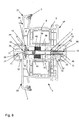
- a bracket 27 attached to the storage of a roller shutter shaft.
- the Bracket 27 is associated with an angle leg 22 Flange plate 28 and a bearing part 29 assembled, the bearing part 29 with the flange plate 28 and this is in turn screwed to the angle leg 22.
- the bracket 27 has the angle leg 22 a plurality of spaced-apart through bores 30.
- Cover strip 13 with sealing strips 32 designed as sealing lips 33 provided, each with a sealing lip 32 one on an outer side 34 of the frame 3 Longitudinal side of the cover strip 13 is assigned.
- the sealing lips 32 are in one Indentation 35 of the cover strip 13 inserted. In the recess 35 are directly adjacent to the fastening web 12 Grooves 36 incorporated.
- the thickness of the frame 3 is greater dimensioned as the width of the reinforcing element 1, so that both the free end of the foot 8 and the free one End of the web 9 behind the outside 34 or the inside 37 of the frame 3 stand back, the foot 8 in Chambers 38 of the frame 3 is used.
- the bridge 9 carries 14 insulation elements 39 in the area of the constriction in chambers 38 of the frame 3 protrude and there at one Support limit bar 40.
- Both in the recording 11 of the foot 8 and in the receptacle 17 of the web 9 each a profiled fastening web 12 one in cross section essentially semi-circular cover strip 13 used such that the sealing lips 32 of the cover strips 13 sealing on the outside 34 or the inside 37 the frame 3 come to rest.
- the reinforcing element 1 is between FIGS. 2 and 7 between two frames 3 arranged opposite the 1 have a smaller thickness, which is why the free end 18 of the web 9 slightly above the Inside 37 of the frame 3 protrudes. It sticks out in the recess 35 of the associated cover strip 13, wherein both cover strips 13 are flattened on the end face are.
- the foot 8 of the reinforcing element 1 is in turn opposite chambers 38 of the frame 3 used.
- the insulation elements used in chambers 38 of the frame 3 39 are supported on the one hand on the web 9 of the reinforcing element 1 and on the other at boundary webs 40 the frame 3 from.
- the frame 3 according to FIGS. 3 and 8 are in their thickness compared to the frame 3 shown in FIG. 2 reduced, so that the free end 18 of the web 9 in the grooves 36 of the associated cover strip 13 protrudes.
- the foot 8 of the Reinforcing element 1 is in turn in chambers 38 Frame 3 set. 4 are mutual Cover strips 13 are essentially trapezoidal in cross section executed.
- the frame 3 of FIGS. 5 and 9 are compared to the 3, again reduced in thickness, so that on the one hand the foot 8 of the reinforcing element 1 on the outside 34 of the adjacent frame rests and in the recess 35 of the associated cover strip 13 protrudes and the free end 18 of the web 9 in the Grooves 36 of the associated cover strip 13 engages.
Landscapes
- Engineering & Computer Science (AREA)
- Mechanical Engineering (AREA)
- Civil Engineering (AREA)
- Structural Engineering (AREA)
- Door And Window Frames Mounted To Openings (AREA)
- Wing Frames And Configurations (AREA)
- Window Of Vehicle (AREA)
- Body Structure For Vehicles (AREA)
- Panels For Use In Building Construction (AREA)
- Operating, Guiding And Securing Of Roll- Type Closing Members (AREA)
Abstract
Description
- Fig. 1
- eine Schnittdarstellung durch Kunststoffprofile von zwei benachbarten Blendrahmen unter Zwischenanordnung eines erfindungsgemäßen Verstärkungselementes,
- Fig. 2 bis Fig. 9
- weitere Schnittdarstellungen alternativ ausgestalteter Kunststoffprofile mit dem Verstärkungselement nach Fig. 1,
- Fig. 10
- eine Seitenansicht eines Haltewinkels für das Verstärkungselement nach Fig. 1,
- Fig. 11
- eine Draufsicht auf den Haltewinkel nach Fig. 6 und
- Fig. 12
- eine Seitenansicht eines Haltewinkels nach Fig. 6 in alternativer Ausgestaltung.
- 1.
- Verstärkungselement
- 2.
- Kunststoffprofil
- 3.
- Blendrahmen
- 4.
- Hohlkammer
- 5.
- Dichtung
- 6.
- Verstärkungsprofil
- 7.
- Bohrung
- 8.
- Fuß
- 9.
- Steg
- 10.
- Längsseite von 8
- 11.
- Aufnahme von 8
- 12.
- Befestigungssteg
- 13.
- Blendleiste
- 14.
- Einschnürung
- 15.
- Kammer
- 16.
- Kammerabschnitt
- 17.
- Aufnahme von 9
- 18.
- freies Ende von 9
- 19.
- Schenkel von 17
- 20.
- Steg von 17
- 21.
- 1. Blendrahmen
- 22.
- Winkelschenkel
- 23.
- Haltewinkel
- 24.
- Flanschplatte
- 25.
- 2. Blendrahmen
- 26.
- Bohrung
- 27.
- Halterung
- 28.
- Flanschblech
- 29.
- Lagerteil
- 30.
- Durchgangsbohrung
- 31.
- Spalt
- 32.
- Dichtlippe
- 33.
- Dichtleiste
- 34.
- Außenseite von 3
- 35.
- Vertiefung
- 36.
- Nut
- 37.
- Innenseite von 3
- 38.
- Kammer
- 39.
- Dämmelement
- 40.
- Begrenzungssteg
- 41.
- Einlaufschräge
- 42.
- Haltearm
Claims (15)
- Verstärkungselement zur Anordnung zwischen zwei Kunststoffprofilen (2) benachbarter Blendrahmen (3, 21, 25), insbesondere von Kunststofffenstern und/oder -türen, das sich über die gesamte Länge der Kunststoffprofile (2) erstreckt und an jeder Längsseite eine Aufnahme (11, 17) zur kraftschlüssigen Festlegung eines Befestigungssteges (12) einer Blendleiste (13) aufweist, gekennzeichnet durch eine im Querschnitt T-förmige Ausgestaltung, wobei der Fuß (8) und der Steg (9) jeweils mittig mit der Aufnahme (11, 17) für den Befestigungssteg (12) der Blendleiste (13) versehen sind.
- Verstärkungselement nach Anspruch 1, dadurch gekennzeichnet, dass der Fuß (8) an jeder seiner Längsseiten (10) um 180° nach außen gebörtelt ist und eine im Querschnitt V-förmige Einlaufschräge (41) für den Befestigungssteg (12) aufweist.
- Verstärkungselement nach Anspruch 1, dadurch gekennzeichnet, dass der Fuß (8) an jeder seiner Längsseiten (10) um 180° nach innen gebörtelt ist.
- Verstärkungselement nach einem der Ansprüche 1 bis 3, dadurch gekennzeichnet, dass sich die dem Fuß (8) zugeordnete Aufnahme (11) für die Blendleiste (13) zu einer Kammer (15) im Steg (9) aufweitet.
- Verstärkungselement nach Anspruch 4, dadurch gekennzeichnet, dass die Kammer (15) durch eine Einschnürung (14) des Steges (9) geteilt ist.
- Verstärkungselement nach Anspruch 4, dadurch gekennzeichnet, dass der Steg (9) derart beidseitig nach innen gebörtelt ist, dass ineinander greifende Haltearme (42) mit jeweils endseitiger Abkröpfung ausgebildet sind, die die Kammer (15) des Steges (9) unterteilen.
- Verstärkungselement nach Anspruch 5 oder 6, dadurch gekennzeichnet, dass der dem Fuß (8) abgewandte Kammerabschnitt (16) zur Aufnahme mindestens eines bauwerkseitig zu befestigenden Haltewinkels (23) dient.
- Verstärkungselement nach einem der Ansprüche 1 bis 7, dadurch gekennzeichnet, dass die dem Steg (9) zugeordnete Aufnahme (17) für die Blendleiste (13) U-förmig ausgebildet ist, wobei die beiden Schenkel (19) der Aufnahme (17) parallel zur Außenkontur des Steges (9) verlaufen und der die Schenkel (19) verbindende Steg (20) die Kammer (15) begrenzt.
- Verstärkungselement nach einem der Ansprüche 1 bis 8, dadurch gekennzeichnet, dass der Fuß (8) und der Steg (9) einstückig aus einem Blech gefertigt sind.
- Verstärkungselement nach Anspruch 1, dadurch gekennzeichnet, dass jede Blendleiste (13) auf der dem Befestigungssteg (12) zugewandten Längsseite mit einer Vertiefung (35) zur Aufnahme von Dichtleisten (33) versehen ist.
- Verstärkungselement nach Anspruch 10, dadurch gekennzeichnet, dass die Dichtleisten (33) als Dichtlippen (32) ausgebildet sind, die derart in der Vertiefung (35) angeordnet sind, dass sie von der Blendleiste (13) überdeckt auf dem jeweils zugeordneten Kunststoffprofil (2) abdichtend aufliegen.
- Verstärkungselement nach einem der Ansprüche 1 bis 11, dadurch gekennzeichnet, dass aufbeiden Seiten des Befestigungssteges (12) eine Nut (36) zur Aufnahme des freien Endes (18) des Steges (9) in die Vertiefung (35) der Blendleiste (13) eingelassen ist.
- Verstärkungselement nach einem der Ansprüche 1 bis 12, dadurch gekennzeichnet, dass der Steg (9) in Kammern (38) der Kunststoffprofile (2) ragende Dämmelemente (39) trägt.
- Verstärkungselement nach Anspruch 7, dadurch gekennzeichnet, dass der rechtwinklige Haltewinkel (23) aus einer Flanschplatte (24) und einem Winkelschenkel (22) besteht, wobei die Flanschplatte (24) mit Bohrungen (26) zur bauwerkseitigen Befestigung versehen ist und der Winkelschenkel (22) sich stirnseitig in den Kammerabschnitt (16) erstreckt.
- Verstärkungselement nach Anspruch 14, dadurch gekennzeichnet, dass der Winkelschenkel (22) des Haltewinkels (23) mit einer 2-dimensional verstellbaren Halterung (27) zur Aufnahme einer Rollladenwelle versehen ist.
Applications Claiming Priority (2)
| Application Number | Priority Date | Filing Date | Title |
|---|---|---|---|
| DE10304389 | 2003-02-03 | ||
| DE10304389A DE10304389B4 (de) | 2003-02-03 | 2003-02-03 | Verstärkungselement zur Anordnung zwischen zwei Kunststoffprofilen benachbarter Blendrahmen |
Publications (3)
| Publication Number | Publication Date |
|---|---|
| EP1443169A2 true EP1443169A2 (de) | 2004-08-04 |
| EP1443169A3 EP1443169A3 (de) | 2005-04-20 |
| EP1443169B1 EP1443169B1 (de) | 2007-04-25 |
Family
ID=32603136
Family Applications (1)
| Application Number | Title | Priority Date | Filing Date |
|---|---|---|---|
| EP04001550A Expired - Lifetime EP1443169B1 (de) | 2003-02-03 | 2004-01-26 | Verstärkungselement zur Anordnung zwischen zwei Kunststoffprofilen benachbarter Blendrahmen |
Country Status (3)
| Country | Link |
|---|---|
| EP (1) | EP1443169B1 (de) |
| AT (1) | ATE360740T1 (de) |
| DE (2) | DE10304389B4 (de) |
Cited By (1)
| Publication number | Priority date | Publication date | Assignee | Title |
|---|---|---|---|---|
| DK201370339A1 (en) * | 2013-06-21 | 2015-01-12 | Vkr Holding As | A window arrangement comprising a plurality of window systems and at least one accessory element |
Families Citing this family (1)
| Publication number | Priority date | Publication date | Assignee | Title |
|---|---|---|---|---|
| DE102007026749A1 (de) * | 2007-06-09 | 2008-12-11 | Profine Gmbh | Verbindungsprofil |
Citations (1)
| Publication number | Priority date | Publication date | Assignee | Title |
|---|---|---|---|---|
| DE19855966A1 (de) | 1998-03-27 | 1999-09-30 | Helmut Over | Träger für Fensterrahmen, Fassaden oder dergleichen |
Family Cites Families (7)
| Publication number | Priority date | Publication date | Assignee | Title |
|---|---|---|---|---|
| DE8708611U1 (de) * | 1987-06-20 | 1987-10-22 | Over, Christa Maria | Träger für Fensterrahmen |
| DE8811361U1 (de) * | 1988-09-08 | 1988-10-27 | Over, Helmut, 5352 Zülpich | Befestigungsmittel für einen Träger für Fensterrahmen |
| DE3929716A1 (de) * | 1989-01-25 | 1990-08-02 | Helmut Over | Fensterband mit abstandselementen |
| DE4107743A1 (de) * | 1990-03-09 | 1992-01-23 | Rudolf Strobel | Pfosten bzw. pfette fuer eine leichtbauwand aus bauelementen, insbesondere kunststoffenstern |
| US5435106A (en) * | 1994-01-18 | 1995-07-25 | Aluminum Company Of America | Metal reinforced mullion for windows |
| DE10028802A1 (de) * | 2000-06-15 | 2001-12-20 | Helmut Over | Bauelement und Verwendung eines Trägers sowie Verfahren zur Herstellung eines Fassadenelementes |
| US6662512B2 (en) * | 2000-06-30 | 2003-12-16 | Certainteed Corporation | Two-piece mullion reinforcement |
-
2003
- 2003-02-03 DE DE10304389A patent/DE10304389B4/de not_active Expired - Fee Related
-
2004
- 2004-01-26 DE DE502004003578T patent/DE502004003578D1/de not_active Expired - Fee Related
- 2004-01-26 EP EP04001550A patent/EP1443169B1/de not_active Expired - Lifetime
- 2004-01-26 AT AT04001550T patent/ATE360740T1/de not_active IP Right Cessation
Patent Citations (1)
| Publication number | Priority date | Publication date | Assignee | Title |
|---|---|---|---|---|
| DE19855966A1 (de) | 1998-03-27 | 1999-09-30 | Helmut Over | Träger für Fensterrahmen, Fassaden oder dergleichen |
Cited By (2)
| Publication number | Priority date | Publication date | Assignee | Title |
|---|---|---|---|---|
| DK201370339A1 (en) * | 2013-06-21 | 2015-01-12 | Vkr Holding As | A window arrangement comprising a plurality of window systems and at least one accessory element |
| US9777533B2 (en) | 2013-06-21 | 2017-10-03 | Vkr Holding A/S | Window arrangement comprising a plurality of window systems and at least one accessory element |
Also Published As
| Publication number | Publication date |
|---|---|
| DE502004003578D1 (de) | 2007-06-06 |
| EP1443169B1 (de) | 2007-04-25 |
| EP1443169A3 (de) | 2005-04-20 |
| DE10304389A1 (de) | 2004-08-26 |
| ATE360740T1 (de) | 2007-05-15 |
| DE10304389B4 (de) | 2006-05-11 |
Similar Documents
| Publication | Publication Date | Title |
|---|---|---|
| EP3080375B2 (de) | Vorrichtung für das verschliessen einer gebäudeöffnung | |
| DE202014009250U1 (de) | Dichtungsvorrichtung für einen verschiebbaren Flügel als Schiebeflügel oder verschiebbaren Hebe-Schiebeflügel eines Fensters oder einer Tür | |
| DE3317948A1 (de) | Tragwerk fuer glasfassaden, -waende und/oder -daecher | |
| EP2666948A1 (de) | Rahmenanordnung für ein Sektionaltorpaneel | |
| DE102019107996A1 (de) | Rahmen für ein Fenster oder eine Tür | |
| EP2754842B1 (de) | Dichtungsprofil für ein Rahmenprofil und Rahmenprofil | |
| DE20011195U1 (de) | Halteteil für eine Fassadenverkleidung | |
| EP1443169B1 (de) | Verstärkungselement zur Anordnung zwischen zwei Kunststoffprofilen benachbarter Blendrahmen | |
| EP2754839B1 (de) | Rahmen oder T-Verbindung und Verfahren zur Montage eines Rahmens oder einer T-Verbindung | |
| DE20304176U1 (de) | Verstärkungselement zur Anordnung zwischen zwei Kunststoffprofilen benachbarter Blendrahmen | |
| DE102016104583A1 (de) | Profilsystem für Flügelelemente von Fassaden | |
| DE102004015064A1 (de) | Fenster oder Tür mit einer im Falzbereich angeordneten Mitteldichtung | |
| EP0742335A2 (de) | Flügelrahmen eines Fensters oder dergleichen | |
| DE29704349U1 (de) | Hohlprofil, insbesondere aus Kunststoff, zur Bildung eines Abdeckrahmens zur Verkleidung von Holzrahmen | |
| EP3150792B1 (de) | Thermisch getrenntes profilrahmensystem | |
| EP2487313A1 (de) | Rahmenkonstruktion für ein Fenster oder eine Tür | |
| DE29920777U1 (de) | Fensteranordnung | |
| DE20100618U1 (de) | Rahmenprofil | |
| DE19611170C2 (de) | Wetterschutzschiene | |
| DE202007015319U1 (de) | Isolator für Fenster-, Tür- und Fassadensysteme | |
| DE102019122295A1 (de) | Eckverbinder für eine Vollschale eines Vorsatzrahmens für ein Fensterprofil | |
| DE29805607U1 (de) | Wärmegedämmtes Fenster in Blockkonstruktion | |
| EP3879061B1 (de) | Schiebetür und bausatz für eine schiebetür | |
| DE29716361U1 (de) | Gebäudefenster und/oder Gebäudefenstertür | |
| EP2372038B1 (de) | Fassadenkonstruktion |
Legal Events
| Date | Code | Title | Description |
|---|---|---|---|
| PUAI | Public reference made under article 153(3) epc to a published international application that has entered the european phase |
Free format text: ORIGINAL CODE: 0009012 |
|
| AK | Designated contracting states |
Kind code of ref document: A2 Designated state(s): AT BE BG CH CY CZ DE DK EE ES FI FR GB GR HU IE IT LI LU MC NL PT RO SE SI SK TR |
|
| AX | Request for extension of the european patent |
Extension state: AL LT LV MK |
|
| PUAL | Search report despatched |
Free format text: ORIGINAL CODE: 0009013 |
|
| AK | Designated contracting states |
Kind code of ref document: A3 Designated state(s): AT BE BG CH CY CZ DE DK EE ES FI FR GB GR HU IE IT LI LU MC NL PT RO SE SI SK TR |
|
| AX | Request for extension of the european patent |
Extension state: AL LT LV MK |
|
| 17P | Request for examination filed |
Effective date: 20051013 |
|
| AKX | Designation fees paid |
Designated state(s): AT BE BG CH CY CZ DE DK EE ES FI FR GB GR HU IE IT LI LU MC NL PT RO SE SI SK TR |
|
| GRAP | Despatch of communication of intention to grant a patent |
Free format text: ORIGINAL CODE: EPIDOSNIGR1 |
|
| GRAS | Grant fee paid |
Free format text: ORIGINAL CODE: EPIDOSNIGR3 |
|
| GRAA | (expected) grant |
Free format text: ORIGINAL CODE: 0009210 |
|
| AK | Designated contracting states |
Kind code of ref document: B1 Designated state(s): AT BE BG CH CY CZ DE DK EE ES FI FR GB GR HU IE IT LI LU MC NL PT RO SE SI SK TR |
|
| PG25 | Lapsed in a contracting state [announced via postgrant information from national office to epo] |
Ref country code: FI Free format text: LAPSE BECAUSE OF FAILURE TO SUBMIT A TRANSLATION OF THE DESCRIPTION OR TO PAY THE FEE WITHIN THE PRESCRIBED TIME-LIMIT Effective date: 20070425 |
|
| REG | Reference to a national code |
Ref country code: GB Ref legal event code: FG4D Free format text: NOT ENGLISH |
|
| REG | Reference to a national code |
Ref country code: IE Ref legal event code: FG4D Free format text: LANGUAGE OF EP DOCUMENT: GERMAN |
|
| REG | Reference to a national code |
Ref country code: CH Ref legal event code: EP |
|
| REF | Corresponds to: |
Ref document number: 502004003578 Country of ref document: DE Date of ref document: 20070606 Kind code of ref document: P |
|
| PG25 | Lapsed in a contracting state [announced via postgrant information from national office to epo] |
Ref country code: SE Free format text: LAPSE BECAUSE OF FAILURE TO SUBMIT A TRANSLATION OF THE DESCRIPTION OR TO PAY THE FEE WITHIN THE PRESCRIBED TIME-LIMIT Effective date: 20070725 |
|
| PG25 | Lapsed in a contracting state [announced via postgrant information from national office to epo] |
Ref country code: ES Free format text: LAPSE BECAUSE OF FAILURE TO SUBMIT A TRANSLATION OF THE DESCRIPTION OR TO PAY THE FEE WITHIN THE PRESCRIBED TIME-LIMIT Effective date: 20070805 |
|
| PG25 | Lapsed in a contracting state [announced via postgrant information from national office to epo] |
Ref country code: PT Free format text: LAPSE BECAUSE OF FAILURE TO SUBMIT A TRANSLATION OF THE DESCRIPTION OR TO PAY THE FEE WITHIN THE PRESCRIBED TIME-LIMIT Effective date: 20070925 |
|
| NLV1 | Nl: lapsed or annulled due to failure to fulfill the requirements of art. 29p and 29m of the patents act | ||
| GBV | Gb: ep patent (uk) treated as always having been void in accordance with gb section 77(7)/1977 [no translation filed] |
Effective date: 20070425 |
|
| REG | Reference to a national code |
Ref country code: IE Ref legal event code: FD4D |
|
| EN | Fr: translation not filed | ||
| PLAZ | Examination of admissibility of opposition: despatch of communication + time limit |
Free format text: ORIGINAL CODE: EPIDOSNOPE2 |
|
| PG25 | Lapsed in a contracting state [announced via postgrant information from national office to epo] |
Ref country code: BG Free format text: LAPSE BECAUSE OF FAILURE TO SUBMIT A TRANSLATION OF THE DESCRIPTION OR TO PAY THE FEE WITHIN THE PRESCRIBED TIME-LIMIT Effective date: 20070725 Ref country code: DK Free format text: LAPSE BECAUSE OF FAILURE TO SUBMIT A TRANSLATION OF THE DESCRIPTION OR TO PAY THE FEE WITHIN THE PRESCRIBED TIME-LIMIT Effective date: 20070425 Ref country code: CZ Free format text: LAPSE BECAUSE OF FAILURE TO SUBMIT A TRANSLATION OF THE DESCRIPTION OR TO PAY THE FEE WITHIN THE PRESCRIBED TIME-LIMIT Effective date: 20070425 Ref country code: SI Free format text: LAPSE BECAUSE OF FAILURE TO SUBMIT A TRANSLATION OF THE DESCRIPTION OR TO PAY THE FEE WITHIN THE PRESCRIBED TIME-LIMIT Effective date: 20070425 Ref country code: NL Free format text: LAPSE BECAUSE OF FAILURE TO SUBMIT A TRANSLATION OF THE DESCRIPTION OR TO PAY THE FEE WITHIN THE PRESCRIBED TIME-LIMIT Effective date: 20070425 Ref country code: IE Free format text: LAPSE BECAUSE OF FAILURE TO SUBMIT A TRANSLATION OF THE DESCRIPTION OR TO PAY THE FEE WITHIN THE PRESCRIBED TIME-LIMIT Effective date: 20070425 |
|
| PLBI | Opposition filed |
Free format text: ORIGINAL CODE: 0009260 |
|
| PLBA | Examination of admissibility of opposition: reply received |
Free format text: ORIGINAL CODE: EPIDOSNOPE4 |
|
| PLAX | Notice of opposition and request to file observation + time limit sent |
Free format text: ORIGINAL CODE: EPIDOSNOBS2 |
|
| PG25 | Lapsed in a contracting state [announced via postgrant information from national office to epo] |
Ref country code: SK Free format text: LAPSE BECAUSE OF FAILURE TO SUBMIT A TRANSLATION OF THE DESCRIPTION OR TO PAY THE FEE WITHIN THE PRESCRIBED TIME-LIMIT Effective date: 20070425 |
|
| 26 | Opposition filed |
Opponent name: OVER, HELMUT Effective date: 20080124 |
|
| PG25 | Lapsed in a contracting state [announced via postgrant information from national office to epo] |
Ref country code: IT Free format text: LAPSE BECAUSE OF FAILURE TO SUBMIT A TRANSLATION OF THE DESCRIPTION OR TO PAY THE FEE WITHIN THE PRESCRIBED TIME-LIMIT Effective date: 20070425 Ref country code: GR Free format text: LAPSE BECAUSE OF FAILURE TO SUBMIT A TRANSLATION OF THE DESCRIPTION OR TO PAY THE FEE WITHIN THE PRESCRIBED TIME-LIMIT Effective date: 20070726 Ref country code: FR Free format text: LAPSE BECAUSE OF FAILURE TO SUBMIT A TRANSLATION OF THE DESCRIPTION OR TO PAY THE FEE WITHIN THE PRESCRIBED TIME-LIMIT Effective date: 20071221 Ref country code: GB Free format text: LAPSE BECAUSE OF FAILURE TO SUBMIT A TRANSLATION OF THE DESCRIPTION OR TO PAY THE FEE WITHIN THE PRESCRIBED TIME-LIMIT Effective date: 20070425 |
|
| PG25 | Lapsed in a contracting state [announced via postgrant information from national office to epo] |
Ref country code: RO Free format text: LAPSE BECAUSE OF FAILURE TO SUBMIT A TRANSLATION OF THE DESCRIPTION OR TO PAY THE FEE WITHIN THE PRESCRIBED TIME-LIMIT Effective date: 20070425 |
|
| PGFP | Annual fee paid to national office [announced via postgrant information from national office to epo] |
Ref country code: AT Payment date: 20071227 Year of fee payment: 5 |
|
| PLBB | Reply of patent proprietor to notice(s) of opposition received |
Free format text: ORIGINAL CODE: EPIDOSNOBS3 |
|
| BERE | Be: lapsed |
Owner name: ZENTRA G.M.B.H. Effective date: 20080131 |
|
| PGFP | Annual fee paid to national office [announced via postgrant information from national office to epo] |
Ref country code: DE Payment date: 20080322 Year of fee payment: 5 |
|
| RAP2 | Party data changed (patent owner data changed or rights of a patent transferred) |
Owner name: ROEMPLER GMBH FENSTER-TUEREN-ROLLADEN |
|
| PG25 | Lapsed in a contracting state [announced via postgrant information from national office to epo] |
Ref country code: MC Free format text: LAPSE BECAUSE OF NON-PAYMENT OF DUE FEES Effective date: 20080131 |
|
| REG | Reference to a national code |
Ref country code: CH Ref legal event code: PL |
|
| PG25 | Lapsed in a contracting state [announced via postgrant information from national office to epo] |
Ref country code: LI Free format text: LAPSE BECAUSE OF NON-PAYMENT OF DUE FEES Effective date: 20080131 Ref country code: CH Free format text: LAPSE BECAUSE OF NON-PAYMENT OF DUE FEES Effective date: 20080131 |
|
| PG25 | Lapsed in a contracting state [announced via postgrant information from national office to epo] |
Ref country code: FR Free format text: LAPSE BECAUSE OF FAILURE TO SUBMIT A TRANSLATION OF THE DESCRIPTION OR TO PAY THE FEE WITHIN THE PRESCRIBED TIME-LIMIT Effective date: 20070425 |
|
| PG25 | Lapsed in a contracting state [announced via postgrant information from national office to epo] |
Ref country code: EE Free format text: LAPSE BECAUSE OF FAILURE TO SUBMIT A TRANSLATION OF THE DESCRIPTION OR TO PAY THE FEE WITHIN THE PRESCRIBED TIME-LIMIT Effective date: 20070425 |
|
| PG25 | Lapsed in a contracting state [announced via postgrant information from national office to epo] |
Ref country code: BE Free format text: LAPSE BECAUSE OF NON-PAYMENT OF DUE FEES Effective date: 20080131 |
|
| PG25 | Lapsed in a contracting state [announced via postgrant information from national office to epo] |
Ref country code: CY Free format text: LAPSE BECAUSE OF FAILURE TO SUBMIT A TRANSLATION OF THE DESCRIPTION OR TO PAY THE FEE WITHIN THE PRESCRIBED TIME-LIMIT Effective date: 20070425 |
|
| PG25 | Lapsed in a contracting state [announced via postgrant information from national office to epo] |
Ref country code: DE Free format text: LAPSE BECAUSE OF NON-PAYMENT OF DUE FEES Effective date: 20090801 Ref country code: AT Free format text: LAPSE BECAUSE OF NON-PAYMENT OF DUE FEES Effective date: 20090126 |
|
| PLBD | Termination of opposition procedure: decision despatched |
Free format text: ORIGINAL CODE: EPIDOSNOPC1 |
|
| PLBM | Termination of opposition procedure: date of legal effect published |
Free format text: ORIGINAL CODE: 0009276 |
|
| STAA | Information on the status of an ep patent application or granted ep patent |
Free format text: STATUS: OPPOSITION PROCEDURE CLOSED |
|
| 27C | Opposition proceedings terminated |
Effective date: 20100108 |
|
| PG25 | Lapsed in a contracting state [announced via postgrant information from national office to epo] |
Ref country code: LU Free format text: LAPSE BECAUSE OF NON-PAYMENT OF DUE FEES Effective date: 20080126 Ref country code: HU Free format text: LAPSE BECAUSE OF FAILURE TO SUBMIT A TRANSLATION OF THE DESCRIPTION OR TO PAY THE FEE WITHIN THE PRESCRIBED TIME-LIMIT Effective date: 20071026 |
|
| PG25 | Lapsed in a contracting state [announced via postgrant information from national office to epo] |
Ref country code: TR Free format text: LAPSE BECAUSE OF FAILURE TO SUBMIT A TRANSLATION OF THE DESCRIPTION OR TO PAY THE FEE WITHIN THE PRESCRIBED TIME-LIMIT Effective date: 20070425 |