EP3879061B1 - Schiebetür und bausatz für eine schiebetür - Google Patents
Schiebetür und bausatz für eine schiebetür Download PDFInfo
- Publication number
- EP3879061B1 EP3879061B1 EP21156884.5A EP21156884A EP3879061B1 EP 3879061 B1 EP3879061 B1 EP 3879061B1 EP 21156884 A EP21156884 A EP 21156884A EP 3879061 B1 EP3879061 B1 EP 3879061B1
- Authority
- EP
- European Patent Office
- Prior art keywords
- profile
- sliding door
- threshold
- ground sill
- sliding
- Prior art date
- Legal status (The legal status is an assumption and is not a legal conclusion. Google has not performed a legal analysis and makes no representation as to the accuracy of the status listed.)
- Active
Links
Images

Classifications
-
- E—FIXED CONSTRUCTIONS
- E06—DOORS, WINDOWS, SHUTTERS, OR ROLLER BLINDS IN GENERAL; LADDERS
- E06B—FIXED OR MOVABLE CLOSURES FOR OPENINGS IN BUILDINGS, VEHICLES, FENCES OR LIKE ENCLOSURES IN GENERAL, e.g. DOORS, WINDOWS, BLINDS, GATES
- E06B3/00—Window sashes, door leaves, or like elements for closing wall or like openings; Layout of fixed or moving closures, e.g. windows in wall or like openings; Features of rigidly-mounted outer frames relating to the mounting of wing frames
- E06B3/32—Arrangements of wings characterised by the manner of movement; Arrangements of movable wings in openings; Features of wings or frames relating solely to the manner of movement of the wing
- E06B3/34—Arrangements of wings characterised by the manner of movement; Arrangements of movable wings in openings; Features of wings or frames relating solely to the manner of movement of the wing with only one kind of movement
- E06B3/42—Sliding wings; Details of frames with respect to guiding
- E06B3/46—Horizontally-sliding wings
- E06B3/4636—Horizontally-sliding wings for doors
-
- E—FIXED CONSTRUCTIONS
- E06—DOORS, WINDOWS, SHUTTERS, OR ROLLER BLINDS IN GENERAL; LADDERS
- E06B—FIXED OR MOVABLE CLOSURES FOR OPENINGS IN BUILDINGS, VEHICLES, FENCES OR LIKE ENCLOSURES IN GENERAL, e.g. DOORS, WINDOWS, BLINDS, GATES
- E06B1/00—Border constructions of openings in walls, floors, or ceilings; Frames to be rigidly mounted in such openings
- E06B1/70—Sills; Thresholds
- E06B1/702—Window sills
-
- E—FIXED CONSTRUCTIONS
- E06—DOORS, WINDOWS, SHUTTERS, OR ROLLER BLINDS IN GENERAL; LADDERS
- E06B—FIXED OR MOVABLE CLOSURES FOR OPENINGS IN BUILDINGS, VEHICLES, FENCES OR LIKE ENCLOSURES IN GENERAL, e.g. DOORS, WINDOWS, BLINDS, GATES
- E06B3/00—Window sashes, door leaves, or like elements for closing wall or like openings; Layout of fixed or moving closures, e.g. windows in wall or like openings; Features of rigidly-mounted outer frames relating to the mounting of wing frames
- E06B3/30—Coverings, e.g. protecting against weather, for decorative purposes
- E06B3/301—Coverings, e.g. protecting against weather, for decorative purposes consisting of prefabricated profiled members or glass
- E06B3/305—Covering metal frames with plastic or metal profiled members
-
- E—FIXED CONSTRUCTIONS
- E06—DOORS, WINDOWS, SHUTTERS, OR ROLLER BLINDS IN GENERAL; LADDERS
- E06B—FIXED OR MOVABLE CLOSURES FOR OPENINGS IN BUILDINGS, VEHICLES, FENCES OR LIKE ENCLOSURES IN GENERAL, e.g. DOORS, WINDOWS, BLINDS, GATES
- E06B3/00—Window sashes, door leaves, or like elements for closing wall or like openings; Layout of fixed or moving closures, e.g. windows in wall or like openings; Features of rigidly-mounted outer frames relating to the mounting of wing frames
- E06B3/30—Coverings, e.g. protecting against weather, for decorative purposes
- E06B3/301—Coverings, e.g. protecting against weather, for decorative purposes consisting of prefabricated profiled members or glass
- E06B3/306—Covering plastic frames with metal or plastic profiled members
-
- E—FIXED CONSTRUCTIONS
- E06—DOORS, WINDOWS, SHUTTERS, OR ROLLER BLINDS IN GENERAL; LADDERS
- E06B—FIXED OR MOVABLE CLOSURES FOR OPENINGS IN BUILDINGS, VEHICLES, FENCES OR LIKE ENCLOSURES IN GENERAL, e.g. DOORS, WINDOWS, BLINDS, GATES
- E06B7/00—Special arrangements or measures in connection with doors or windows
- E06B7/14—Measures for draining-off condensed water or water leaking-in frame members for draining off condensation water, throats at the bottom of a sash
-
- E—FIXED CONSTRUCTIONS
- E06—DOORS, WINDOWS, SHUTTERS, OR ROLLER BLINDS IN GENERAL; LADDERS
- E06B—FIXED OR MOVABLE CLOSURES FOR OPENINGS IN BUILDINGS, VEHICLES, FENCES OR LIKE ENCLOSURES IN GENERAL, e.g. DOORS, WINDOWS, BLINDS, GATES
- E06B1/00—Border constructions of openings in walls, floors, or ceilings; Frames to be rigidly mounted in such openings
- E06B1/62—Tightening or covering joints between the border of openings and the frame or between contiguous frames
- E06B2001/628—Separate flexible joint covering strips; Flashings
Definitions
- the present invention relates to a sliding door with a frame which has a threshold and two frames extending upwards at the end of the threshold, and at least one sliding leaf which can be moved along a guide rail on the threshold, wherein a separate compensation profile is fixed to the threshold on a longitudinal edge on an inner side, wherein the compensation profile is essentially rectangular in cross section and is held on the threshold via locking means.
- the EP 3 225 771 A1 discloses a threshold for a sliding door, which has a flat upper side on which a sliding leaf is arranged along a guide rail in a first plane and a fixed panel in a second plane.
- a surface of the fixed panel is arranged substantially flush with a surface on a longitudinal edge of the threshold profile, which simplifies sealing on the outside, in particular if an outer surface of the frame is also arranged flush.
- Frame profiles from different manufacturers can be used to manufacture the fixed panel and the sliding leaf, which have different widths in a direction perpendicular to the longitudinal direction of the threshold and in the horizontal direction. If a fixed panel made of frame profiles is aligned flush with the longitudinal edge of the threshold and the frame profiles on the outside, an inner surface of the sliding leaf can be aligned on the inside with an offset to an inner longitudinal edge of the threshold.
- US2010/0192469 discloses a sliding door with a sliding leaf that can be moved on a floor sill, wherein a plurality of adapter profiles stacked on top of one another can be mounted on the floor sill on an upper side of the floor clamp adjacent to the sliding leaf.
- EP003042 discloses a frame profile for a sliding sash, which has an outer element made of metal and an inner element made of plastic to improve thermal insulation.
- a threshold is provided on a frame on which at least one sliding leaf can be moved via a guide rail, with a separate compensation profile being fixed to the threshold on a longitudinal edge on an inner side.
- a fixed panel and a sliding door can be arranged on the threshold, with the fixed panel and sliding leaf being able to be made from different profiles. Any offset, i.e. an overhang of the sliding door on the inside due to profiles of different thicknesses, can then be compensated for using a separate compensation profile, so that one and the same threshold can be used for different profiles to produce a sliding leaf and a fixed panel.
- the terms “inside” and “outside” refer to an installation situation of the sliding door on a building opening and thus the longitudinal edge on an inner side faces the inside of the building.
- the compensation profile preferably has essentially the same height as the threshold.
- the threshold can, for example, be made from an extruded profile that has a bottom and a top that define the maximum height of the threshold, which preferably corresponds to the height of the compensation profile.
- the threshold profile does not have to have the same height across the entire width, but can, for example, include a drainage channel with a lower height for drainage.
- a longitudinal edge of the threshold is arranged on an outside opposite the inside, essentially flush with an outside of the frame.
- a building seal for example a film
- the sliding door can comprise a fixed panel that has a frame with a filling element, for example an insulating glass pane, whereby an outside of the frame of the fixed panel is flush with an outside of a long edge of the threshold and optionally also an outside of the casing.
- the flush alignment simplifies sealing, for example using a film that is placed on the frame, casing and the outer long edge of the threshold so that rainwater can flow off the outside.
- the installation of the compensation profile on an inner side of the threshold also ensures a flush alignment of a surface of the compensation profile and an inner surface of the sliding sash, which is visually appealing and facilitates the internal connection to a floor structure.
- the compensation profile is held on the threshold by means of locking means.
- the threshold can optionally have at least one groove-shaped locking receptacle on its long edge on the inside, preferably two spaced locking receptacles, into each of which a locking web of the compensation profile is inserted.
- a width compensation can be carried out so that the unit made up of the threshold and compensation profile has approximately the same width as the frame profile and/or the unit made up of the fixed field and sliding sash.
- the term "width" here refers to an extension perpendicular to the plane of a frame of the sliding sash.
- the locking webs can also be formed on the threshold on the long side and engage in locking receptacles on the compensation profile. Alternatively or additionally, it is also possible to glue, screw or fix the compensation profile to the threshold using other fastening means.
- the compensating profile is essentially rectangular in cross-section. Hollow chambers of the compensating profile are not taken into account in the cross-sectional geometry. One or more locking webs can then protrude from this essentially rectangular cross-section on the side facing the threshold profile.
- the compensation profile is essentially angular.
- the guide rail can be supported on a horizontal leg of the compensation profile or can be integrally formed.
- the angular design of the compensation profile has the advantage that the The guide rail is arranged on the compensation profile at a defined distance from the inside of the compensation profile in accordance with the requirements of the respective frame profile. This means that there is no need to move a guide rail on a groove-shaped holder on the threshold profile, as the position of the guide rail is specified by the compensation profile.
- the threshold preferably comprises an extruded threshold profile, for example made of aluminum or plastic, and one or more covers that are fixed to an upper side.
- a cover can cover a drainage channel that serves to drain rainwater to an outside.
- a fixed panel on the sliding door can be fixed to such a cover and can be formed, for example, by a frame and a filling element.
- a kit for a sliding door with a threshold in which different compensation profiles of different thicknesses can be fixed to a long edge of the threshold.
- the compensation profiles can have the same height, and in particular the same fastening means, such as locking bars, in order to be fixed to the threshold profile.
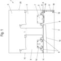
- a sliding door 1 comprises a frame which has a threshold 2 made of a one-part or multi-part extruded threshold profile, on which a frame 3 protrudes upwards on opposite sides.
- the two frames 3 are connected to one another at the top via an upper frame profile.
- a sliding sash 4 is arranged on an upper side of the threshold 2 and can be moved along a guide rail 5.
- the sliding sash 4 can have a downwardly open groove 7 on a lower frame profile, on which one or more carriages with rollers are provided which can be moved along the guide rail 5.
- the sliding sash 4 can also be guided on the upper frame profile between the frames 3.
- a groove-shaped receptacle 6 is formed on an upper side of the threshold 2, into which the guide rail 5 is inserted.
- the sliding leaf 4 can be designed as a lift-sliding door and has at least one sealing profile 8 on the lower frame profile, preferably a sealing profile 8 on each side of the downwardly open groove 7, in order to seal the sliding leaf 4 in the closed position.
- a fixed panel 9 is also provided on the sliding door 1, which has a frame with a filling element, in particular an insulating glass pane.
- a lower frame profile of the fixed panel 9 has a groove that is open at the bottom and into which a fastening means 10 in the form of an upwardly projecting web is inserted.
- the fastening means 10 is fixed to a cover 11 or is formed integrally with it.
- the cover 11 can also be formed integrally with the floor sill 2.
- a drainage channel 12 is arranged below the cover 11, which is inclined to the horizontal, for example at an angle between 2° and 10°, in order to drain rainwater to an outside.
- the fixed panel 9 is sealed to the cover 11 via sealing profiles 8.
- the cover 11 is arranged essentially flush with an upper side of the floor sill 2.
- the lower frame profile of the fixed panel 9 has an outer upper side 14 which is arranged flush with an outer longitudinal edge of the threshold 2, so that drainage of rainwater and sealing are simplified.
- an outer surface of the frame 3 is also aligned flush with the upper side 14.
- an inner side 20 of the frame 3 is arranged flush with an inner side of the frame profiles of the sliding sash 4 and flush with an upper side of a compensation profile 17 which is mounted on a longitudinal edge of the threshold 2.
- two spaced-apart locking receptacles 19 are formed on the threshold 2, into each of which engages a locking web 18 of the compensation profile 17 which is locked to the longitudinal edge of the threshold 2.
- other fastening means can also be provided for fixing the compensation profile 17, for example clamping elements, locking webs on the threshold 2, or separate fastening means such as screws or adhesives.
- the compensation profile 17 forms an outer surface which is essentially flush with the sliding sash 4 and the frame 3 on the inside.
- the compensation profile 17 extends essentially over the entire height of the threshold 2, wherein the maximum height is defined by the area which is formed adjacent to the guide rail 5 on the threshold 2.
- the frames 3 can have the same width as the threshold 2 with the compensation profile 17.
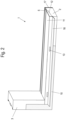
- FIG. 2 the frame of the sliding door 1 is shown without sliding sash 4 and fixed panel 9. It can be seen that a building seal 15 can be easily attached to an outside of the frame, since an outer longitudinal edge of the floor sill 2 is arranged flush with an outside of the frame 3.
- an upwardly projecting web is formed, on which drainage openings 13 are provided in order to be able to drain moisture outwards via the drainage channel 12.
- the cover 11 is supported on the web, whereby the web can optionally also be formed on the cover 11.
- a tread 16 is also formed, which serves to connect the floor sill to an adjacent substrate, whereby the tread 16 is inclined so that moisture can be drained further outwards from the drainage openings 13.
- FIG. 3A to 3C a sliding door with the floor threshold 2 is shown, on which sliding doors 4, 4', 4" and fixed panels 9, 9', 9" are made of profiles with different geometries, in particular different widths.
- a sliding wing 4" and a fixed field 9" are manufactured with different frame profiles, so that starting from a flush alignment of the fixed field 9" on an outside with the outer longitudinal edge of the threshold 2, the overhang of the sliding wing 4" on the inside is slightly less than in the Figure 3A shown embodiment.
- a modified compensation profile 17" is fixed to the longitudinal edge of the threshold 2 via locking webs 18.
- an inner side 20 of the sliding sash 4" is arranged flush with an upper side of the compensation profile 17", with the compensation profile 17" extending over the entire height of the threshold 2.
- FIG 3C is that in Figure 1 shown embodiment is shown schematically.
- the projection of the sliding wing 4 on the inside is smaller than the inner longitudinal edge of the threshold 2.
- the sliding wing 4 is arranged at a predetermined distance L relative to the fixed field 9, the distance being used to install corresponding sealing strips.
- the smaller projection of the sliding wing 4 is compensated by mounting a compensation profile 17 with a smaller thickness on the longitudinal edge of the threshold 2.
- the compensation profiles 17, 17' and 17" extend over the entire height of the threshold 2 on the inner longitudinal edge, but have a different thickness so that the different projection of the Sliding sash 4, 4', 4" can be compensated for by the compensation profiles 17, 17', 17" due to the different widths of the frame profiles used.
- the threshold 2 can thus be used for different geometries of frame profiles from which the sliding wings 4, 4', 4" and the fixed fields 9, 9', 9" are made by mounting corresponding compensation profiles 17, 17', 17" on the inner longitudinal edge of the threshold 2. This provides a high degree of flexibility without the design of the thresholds 2 having to be adapted for each frame profile.
Landscapes
- Engineering & Computer Science (AREA)
- Civil Engineering (AREA)
- Structural Engineering (AREA)
- Door And Window Frames Mounted To Openings (AREA)
- Wing Frames And Configurations (AREA)
Description
- Die vorliegende Erfindung betrifft eine Schiebetür mit einem Blendrahmen, der eine Bodenschwelle und zwei endseitig an der Bodenschwelle sich nach oben erstreckende Zargen aufweist, und mindestens einem Schiebeflügel, der entlang einer Laufschiene an der Bodenschwelle verfahrbar ist, wobei an der Bodenschwelle an einer Längskante an einer Innenseite ein separates Ausgleichsprofil fixiert ist, wobei das Ausgleichsprofil im Querschnitt im Wesentlichen rechteckförmig ausgebildet ist und an der Bodenschwelle über Rastmittel gehalten ist.
- Die
EP 3 225 771 A1 offenbart eine Bodenschwelle für eine Schiebetür, die eine ebene Oberseite aufweist, an der ein Schiebeflügel entlang einer Laufschiene in einer ersten Ebene und ein Festfeld in einer zweiten Ebene angeordnet sind. An der Außenseite ist eine Oberfläche des Festfeldes im Wesentlichen flächenbündig mit einer Oberfläche an einer Längskante des Schwellenprofils angeordnet, was die Abdichtung an der Außenseite vereinfacht, insbesondere wenn auch eine Außenfläche der Zarge flächenbündig angeordnet ist. Für die Herstellung des Festfeldes und des Schiebeflügels können Rahmenprofile unterschiedlicher Hersteller eingesetzt werden, die in eine Richtung senkrecht zur Längsrichtung der Bodenschwelle und in horizontale Richtung unterschiedlich breit sind. Wenn ein Festfeld aus Rahmenprofilen an der Außenseite flächenbündig mit der Längskante der Bodenschwelle und den Zargenprofilen ausgerichtet wird, kann an der Innenseite eine innere Oberfläche des Schiebeflügels mit einem Versatz zu einer inneren Längskante der Bodenschwelle ausgerichtet sein. -
US 2010/0192469 offenbart eine Schiebetür mit einem auf einer Bodenschwelle verfahrbaren Schiebeflügel, wobei an einer Oberseite der Bodenschelle benachbart zu dem Schiebeflügel eine Vielzahl von übereinander gestapelten Adapterprofilen auf der Bodenschwelle montierbar sind. -
EP 003 042 - Es ist daher Aufgabe der vorliegenden Erfindung, eine Schiebetür und einen Bausatz für eine Schiebetür zu schaffen, die den Einsatz unterschiedlicher Rahmenprofile zur Herstellung des Festfeldes und des Schiebeflügels ermöglicht und einen optimierten inneren und äußeren Abschluss gewährleistet.
- Diese Aufgabe wird mit einer Schiebetür mit den Merkmalen des Anspruches 1 sowie einem Bausatz mit den Merkmalen des Anspruches 7 gelöst.
- Bei der erfindungsgemäßen Schiebetür ist eine Bodenschwelle an einem Blendrahmen vorgesehen, an der mindestens ein Schiebeflügel über eine Laufschiene verfahrbar ist, wobei an der Bodenschwelle an einer Längskante an einer Innenseite ein separates Ausgleichsprofil fixiert ist. Dadurch können auf der Bodenschwelle ein Festfeld und eine Schiebetür angeordnet werden, wobei Festfeld und Schiebeflügel aus unterschiedlichen Profilen hergestellt werden können. Ein etwaiger Versatz, also ein Überstand der Schiebetür an der Innenseite aufgrund unterschiedlich dicker Profile, kann dann über ein separates Ausgleichsprofil kompensiert werden, so dass eine und dieselbe Bodenschwelle für unterschiedliche Profile zur Herstellung eines Schiebeflügels und eines Festfeldes eingesetzt werden kann. Die Begriffe "Innenseite" und "Außenseite" beziehen sich dabei auf eine Einbausituation der Schiebetür an einer Gebäudeöffnung und somit ist die Längskante an einer Innenseite der Innenseite des Gebäudes zugewandt ist.
- Das Ausgleichsprofil weist vorzugsweise im Wesentlichen die gleiche Höhe auf die die Bodenschwelle. Die Bodenschwelle kann beispielsweise aus einem extrudierten Profil hergestellt sein, das eine Unterseite und eine Oberseite aufweist, die die maximale Höhe der Bodenschwelle definieren, die vorzugsweise der Höhe des Ausgleichsprofils entspricht. Das Schwellenprofil muss dabei nicht über die gesamte Breite die gleiche Höhe aufweisen, sondern kann beispielsweise zur Entwässerung eine Ablaufrinne mit geringerer Höhe umfassen.
- In einer bevorzugten Ausgestaltung ist einen Längskante der Bodenschwelle an einer zur Innenseite gegenüberliegenden Außenseite im Wesentlichen flächenbündig mit einer Außenseite der Zargen angeordnet. Dadurch kann eine Oberfläche der Zarge und der Bodenschwelle auf einfache Weise mit einer Bauwerksabdichtung, beispielsweise einer Folie, überdeckt werden, um eine Abdichtung zur Außenseite anzubringen. Für eine optisch ansprechende Ausgestaltung kann die Schiebetür ein Festfeld umfassen, das einen Rahmen mit einem Füllungselement besitzt, beispielsweise einer Isolierglasscheibe, wobei eine Außenseite des Rahmens des Festfeldes flächenbündig mit einer Außenseite einer Längskante der Bodenschwelle und optional auch einer Außenseite der Zarge angeordnet ist. Die flächenbündige Ausrichtung vereinfacht die Abdichtung, beispielsweise über eine Folie, die an den Rahmen, die Zarge und die äußere Längskante der Bodenschwelle angelegt wird, damit dann Niederschlagswasser an der Außenseite abströmen kann.
- An einer Innenseite der Bodenschwelle ist erfindungsgemäß durch die Montage des Ausgleichsprofils ebenfalls eine flächenbündige Ausrichtung einer Oberfläche des Ausgleichsprofils und einer inneren Oberfläche des Schiebeflügels erhalten, was optisch ansprechend ist und den inneren Anschluss an einen Bodenaufbau erleichtert.
- Das Ausgleichsprofil ist an der Bodenschwelle erfindungsgemäß über Rastmittel gehalten. Hierfür kann die Bodenschwelle optional an ihrer Längskante an der Innenseite mindestens eine nutförmige Rastaufnahme aufweisen, vorzugsweise zwei beabstandete Rastaufnahmen, in die jeweils ein Raststeg des Ausgleichsprofils eingefügt ist. Durch unterschiedliche Ausgleichsprofile, die eine unterschiedliche Dicke besitzen, kann somit ein Breitenausgleich vorgenommen werden, so dass die Einheit aus Bodenschwelle und Ausgleichsprofil etwa die gleiche Breite besitzt wie das Zargenprofil und/oder die Einheit aus Festfeld und Schiebeflügel. Der Begriff "Breite" bezieht sich hier auf eine Erstreckung senkrecht zur Ebene eines Rahmens des Schiebeflügels. Die Raststege können auch an der Bodenschwelle an der Längsseite ausgebildet sein und in Rastaufnahmen an dem Ausgleichsprofil eingreifen. Zudem ist es alternativ oder zusätzlich möglich, das Ausgleichsprofil an der Bodenschwelle anzukleben, anzuschrauben oder über andere Befestigungsmittel zu fixieren.
- In einer erfindungsgemäßen Ausführungsform ist das Ausgleichsprofil im Querschnitt im Wesentlichen rechteckförmig ausgebildet. Dabei werden bei der Querschnittsgeometrie Hohlkammern des Ausgleichsprofils nicht berücksichtigt. Von diesem im Wesentlichen rechteckförmigen Querschnitt können dann ein oder mehrere Raststege auf der zum Schwellenprofil gewandten Seite hervorstehen.
- In einer alternativen Ausführungsform ist das Ausgleichsprofil im Wesentlichen winkelförmig ausgebildet. Dabei kann an einem horizontalen Schenkel des Ausgleichsprofils die Laufschiene abgestützt oder integral ausgebildet sein. Die winkelförmige Ausgestaltung des Ausgleichsprofils hat den Vorteil, dass die Laufschiene an dem Ausgleichsprofil mit einem definierten Abstand von der Innenseite des Ausgleichsprofils angeordnet ist entsprechend der Anforderung des jeweiligen Rahmenprofils. Ein Verschieben einer Laufschiene an einer nutförmigen Aufnahme an dem Schwellenprofil kann somit entfallen, da die Position der Laufschiene über das Ausgleichsprofil vorgegeben wird.
- Die Bodenschwelle umfasst vorzugsweise ein extrudiertes Schwellenprofil, beispielsweise aus Aluminium oder Kunststoff, und eine oder mehrere Abdeckungen, die an einer Oberseite fixiert sind. Dabei kann eine Abdeckung eine Entwässerungsrinne überdecken, die zum Abführen von Niederschlagswasser zu einer Außenseite hin dient. Ein Festfeld an der Schiebetür kann dabei auf einer solchen Abdeckung fixiert sein und beispielsweise durch einen Rahmen und ein Füllungselement gebildet sein.
- Ferner wird ein Bausatz für eine Schiebetür mit einer Bodenschwelle bereitgestellt, bei dem unterschiedliche Ausgleichsprofile an einer Längskante der Bodenschwelle fixierbar sind, die eine unterschiedliche Dicke aufweisen. Dadurch kann das Handwerksunternehmen, welches die Schiebetür montiert, abhängig von den eingesetzten Profilen zur Herstellung des Rahmens der Schiebetür und eines Festfeldes, ein Ausgleichsprofil auswählen, das an der Bodenschwelle montiert wird. Dadurch kann ein und dieselbe Bodenschwelle für eine Vielzahl unterschiedlicher Rahmenprofile verwendet werden, mit denen ein Überstand der Schiebetür an einer Innenseite kompensiert werden kann. Die Ausgleichsprofile können dabei die gleiche Höhe aufweisen, insbesondere auch die gleichen Befestigungsmittel, wie Raststege, um an dem Schwellenprofil fixiert zu werden.
- Die Erfindung wird nachfolgend anhand mehrerer Ausführungsbeispiele mit Bezug auf die beigefügten Zeichnungen näher erläutert. Es zeigen:
- Figur 1
- eine Schnittansicht durch eine erfindungsgemäße Schiebetür;
- Figur 2
- eine Detailansicht des Blendrahmens in einem unteren Eckbereich; und
- Figuren 3A bis 3C
- mehrere Ansichten einer Schiebetür mit unterschiedlichen Ausgleichsprofilen.
- Eine Schiebetür 1 umfasst einen Blendrahmen, der eine Bodenschwelle 2 aus einem ein oder mehrteiligen extrudierten Schwellenprofil aufweist, an der an gegenüberliegenden Seiten jeweils eine Zarge 3 nach oben hervorsteht. Die beiden Zargen 3 sind an der Oberseite über ein oberes Rahmenprofil miteinander verbunden. An einer Oberseite der Bodenschwelle 2 ist ein Schiebeflügel 4 angeordnet, die entlang einer Laufschiene 5 verfahrbar ist. Hierfür kann der Schiebeflügel 4 an einem unteren Rahmenprofil eine nach unten offene Nut 7 aufweisen, an der ein oder mehrere Laufwägen mit Laufrollen vorgesehen sind, die entlang der Laufschiene 5 verfahrbar sind. Der Schiebeflügel 4 kann zusätzlich an dem oberen Rahmenprofil zwischen den Zargen 3 geführt sein.
- An einer Oberseite der Bodenschwelle 2 ist eine nutförmige Aufnahme 6 ausgebildet, in die die Laufschiene 5 eingefügt ist. Der Schiebeflügel 4 kann als Hebe-Schiebetür ausgebildet sein und weist an dem unteren Rahmenprofil mindestens ein Dichtungsprofil 8, vorzugsweise auf jeder Seite der nach unten offenen Nut 7 ein Dichtungsprofil 8, auf, um den Schiebeflügel 4 in der geschlossenen Position abzudichten.
- An der Schiebetür 1 ist ferner ein Festfeld 9 vorgesehen, das einen Rahmen mit einem Füllungselement aufweist, insbesondere einer Isolierglasscheibe. Ein unteres Rahmenprofil des Festfeldes 9 weist dabei eine nach unten offene Nut auf, in die ein Befestigungsmittel 10 in Form eines nach oben hervorstehenden Steges eingefügt ist. Das Befestigungsmittel 10 ist an einer Abdeckung 11 fixiert oder integral mit dieser ausgebildet. Optional kann die Abdeckung 11 auch integral mit der Bodenschwelle 2 ausgebildet sein. Unterhalb der Abdeckung 11 ist eine Entwässerungsrinne 12 angeordnet, die geneigt zur Horizontalen ausgerichtet ist, beispielsweise in einem Winkel zwischen 2° und 10°, um Niederschlagswasser zu einer Außenseite hin abzuleiten.
- Das Festfeld 9 ist über Dichtungsprofile 8 abgedichtet an der Abdeckung 11 gehalten. Die Abdeckung 11 ist dabei im Wesentlichen flächenbündig mit einer Oberseite der Bodenschwelle 2 angeordnet.
- Das untere Rahmenprofil des Festfeldes 9 weist eine äußere Oberseite 14 auf, die flächenbündig mit einer äußeren Längskante der Bodenschwelle 2 angeordnet ist, so dass ein Ablaufen von Niederschlagswasser und eine Abdichtung vereinfacht sind. Zudem ist auch eine äußere Oberfläche der Zarge 3 flächenbündig mit der Oberseite 14 ausgerichtet.
- An einer inneren Seite ist eine Innenseite 20 der Zarge 3 flächenbündig mit einer Innenseite der Rahmenprofile des Schiebeflügels 4 sowie flächenbündig mit einer Oberseite eines Ausgleichsprofils 17 angeordnet, das an einer Längskante der Bodenschwelle 2 montiert ist. Hierfür sind an der Bodenschwelle 2 zwei beabstandete Rastaufnahmen 19 ausgebildet, in die jeweils ein Raststeg 18 des Ausgleichsprofis 17 eingreift, der an der Längskante der Bodenschwelle 2 verrastet ist. Es können natürlich auch andere Befestigungsmittel zur Fixierung des Ausgleichsprofils 17 vorgesehen sein, beispielsweise Klemmelemente, Raststege an der Bodenschwelle 2, oder separate Befestigungsmittel, wie Schrauben, oder Kleben. In jedem Fall bildet das Ausgleichsprofil 17 eine äußere Oberfläche aus, die an der Innenseite im Wesentlichen flächenbündig mit dem Schiebeflügel 4 und der Zarge 3 ausgerichtet ist. Das Ausgleichsprofil 17 erstreckt sich dabei im Wesentlichen über die gesamte Höhe der Bodenschwelle 2, wobei die maximale Höhe durch den Bereich definiert wird, der benachbart zu der Laufschiene 5 an der Bodenschwelle 2 ausgebildet ist.
- Die Zargen 3 können die gleiche Breite aufweisen wie die Bodenschwelle 2 mit dem Ausgleichsprofil 17.
- In
Figur 2 ist der Blendrahmen der Schiebetür 1 ohne Schiebeflügel 4 und Festfeld 9 gezeigt. Es ist erkennbar, dass eine Bauabdichtung 15 auf einfache Weise an einer Außenseite des Blendrahmens angebracht werden kann, da eine äußere Längskante der Bodenschwelle 2 flächenbündig mit einer Außenseite der Zarge 3 angeordnet ist. An der Bodenschwelle 2 ist ein an der Außenseite ein nach oben ragender Steg ausgebildet, an dem Entwässerungsöffnungen 13 vorgesehen sind, um Feuchtigkeit über die Entwässerungsrinne 12 nach außen ableiten zu können. An dem Steg ist die Abdeckung 11 abgestützt, wobei optional der Steg auch an der Abdeckung 11 ausgebildet sein kann. An der Außenseite der Bodenschwelle 2 ist im Bereich der Längskante ferner noch eine Trittleiste 16 ausgebildet, die zum Anschluss der Bodenschwelle an einen benachbarten Untergrund dient, wobei die Trittleiste 16 geneigt ausgebildet ist, so dass Feuchtigkeit aus den Entwässerungsöffnungen 13 weiter nach außen abgeleitet werden kann. - In den
Figuren 3A bis 3C ist jeweils eine Schiebetür mit der Bodenschwelle 2 gezeigt, an der Schiebetüren 4, 4', 4" und Festfelder 9, 9', 9" aus Profilen mit unterschiedlicher Geometrie, insbesondere unterschiedlicher Breite, hergestellt sind. - In
Figur 3A sind zur Herstellung des Schiebeflügels 4' und des Festfeldes 9' Rahmenprofile mit etwas größerer Breite eingesetzt, wobei das Festgeld 9' so angeordnet ist, dass die Rahmenprofile an der Außenseite flächenbündig mit einer Außenseite der Bodenschwelle 2 ausgerichtet sind. Dadurch ergibt sich bei einem vorbestimmten Abstand L zwischen dem Schiebeflügel 4' und dem Festfeld 9' an der Innenseite ein Überstand des Schiebeflügels 4' gegenüber einer Längskante der Bodenschwelle 2. Um diesen Überstand auszugleichen, ist ein modifiziertes Ausgleichsprofil 17' an der Längskante der Bodenschwelle 2 montiert, das eine größere Dicke besitzt als das Ausgleichsprofil 17 inFigur 1 . Das Ausgleichsprofil 17 schließt an der Außenseite flächenbündig mit einer Innenseite 20 des Schiebeflügels 4 ab. Der Schiebeflügel 4' ist über modifizierte Dichtungsprofile 8' an einer Oberseite der Bodenschwelle 2 abgedichtet gehalten. - In dem Ausführungsbeispiel der
Figur 3B ist ein Schiebeflügel 4" und ein Festfeld 9" mit anderen Rahmenprofilen hergestellt, so dass ausgehend von einer flächenbündigen Ausrichtung des Festfeldes 9" an einer Außenseite mit der äu-ßeren Längskante der Bodenschwelle 2 der Überstand des Schiebeflügels 4" an der Innenseite etwas geringer ist als bei dem inFigur 3A gezeigten Ausführungsbeispiel. Um diesen Überstand auszugleichen, ist ein modifiziertes Ausgleichsprofil 17" an der Längskante der Bodenschwelle 2 über Raststege 18 fixiert. Dadurch ist eine Innenseite 20 des Schiebeflügels 4" flächenbündig mit einer Oberseite des Ausgleichsprofils 17" angeordnet, wobei sich das Ausgleichsprofil 17" über die gesamte Höhe der Bodenschwelle 2 erstreckt. - In
Figur 3C ist das inFigur 1 gezeigte Ausführungsbeispiel schematisch gezeigt. Ausgehend von einer flächenbündigen Ausrichtung einer Oberseite 14 an der Außenseite des Festfeldes 9 zu einer äußeren Längskante der Bodenschwelle 2 ist an der Innenseite der Überstand des Schiebeflügels 4 gegenüber der inneren Längskante der Bodenschwelle 2 kleiner ausgebildet. Der Schiebeflügel 4 ist dabei einem vorbestimmten Abstand L relativ zu dem Festfeld 9 angeordnet, wobei der Abstand zum Einbau entsprechender Dichtleisten dient. Der geringere Überstand des Schiebeflügels 4 wird dadurch kompensiert, dass ein Ausgleichsprofil 17 mit geringerer Dicke an der Längskante der Bodenschwelle 2 montiert wird. - Die Ausgleichsprofile 17, 17' und 17" erstrecken sich dabei über die gesamte Höhe der Bodenschwelle 2 an der inneren Längskante, weisen aber eine unterschiedliche Dicke auf, so dass der unterschiedliche Überstand der Schiebeflügel 4, 4', 4" aufgrund der unterschiedlichen Breite der eingesetzten Rahmenprofile über die Ausgleichsprofile 17, 17', 17" kompensiert werden kann.
- Die Bodenschwelle 2 kann somit für unterschiedliche Geometrien von Rahmenprofilen eingesetzt werden, aus denen die Schiebeflügel 4, 4', 4" und die Festfelder 9, 9', 9" hergestellt werden, indem entsprechende Ausgleichsprofile 17, 17', 17"an der inneren Längskante der Bodenschwelle 2 montiert werden. Dadurch wird ein hohes Maß an Flexibilität erhalten, ohne dass die Konstruktion der Bodenschwellen 2 für jedes Rahmenprofil angepasst werden muss.
-
- 1
- Schiebetür
- 2
- Bodenschwelle
- 3
- Zarge
- 4, 4', 4"
- Schiebeflügel
- 5
- Laufschiene
- 6
- Aufnahme
- 7
- Nut
- 8
- Dichtungsprofil
- 9, 9', 9"
- Festfeld
- 10
- Befestigungsmittel
- 11
- Abdeckung
- 12
- Entwässerungsrinne
- 13
- Entwässerungsöffnung
- 14
- Oberseite
- 15
- Bauabdichtung
- 16
- Trittleiste
- 17, 17', 17"
- Ausgleichsprofil
- 18
- Raststeg
- 19
- Rastaufnahme
- 20
- Innenseite
- L
- Abstand
Claims (8)
- Schiebetür (1) mit einem Blendrahmen, der eine Bodenschwelle (2) und zwei endseitig an der Bodenschwelle (2) sich nach oben erstreckende Zargen (3) aufweist, und mindestens einem Schiebeflügel (4, 4`, 4"), der entlang einer Laufschiene (5, 30) an der Bodenschwelle (2) verfahrbar ist, wobei an der Bodenschwelle (2) an einer Längskante an einer Innenseite ein separates Ausgleichsprofil (17, 17', 17") fixiert ist, wobei das Ausgleichsprofil (17, 17', 17") im Querschnitt im Wesentlichen rechteckförmig ausgebildet ist und an der Bodenschwelle (2, 2') über Rastmittel gehalten ist, dadurch gekennzeichnet, dass an der Innenseite der Bodenschwelle (2) durch die Montage des Ausgleichsprofils (17, 17', 17") eine flächenbündige Ausrichtung einer Oberfläche des Ausgleichsprofils (17, 17', 17") und einer inneren Oberfläche des Schiebeflügels (4, 4', 4") vorgesehen ist.
- Schiebetür nach Anspruch 1, dadurch gekennzeichnet, dass das Ausgleichsprofil (17, 17', 17") im Wesentlichen die gleiche Höhe aufweist wie die Bodenschwelle (2).
- Schiebetür nach Anspruch 1 oder 2, dadurch gekennzeichnet, dass eine Längskante der Bodenschwelle (2) an einer zur Innenseite gegenüberliegenden Außenseite im Wesentlichen flächenbündig mit einer Außenseite der Zargen (3) angeordnet ist.
- Schiebetür nach einem der vorhergehenden Ansprüche, dadurch gekennzeichnet, dass die Schiebetür (1) ein Festfeld (9, 9', 9") umfasst und eine Außenseite eines Rahmens des Festfeldes (9, 9', 9") im Wesentlichen flächenbündig mit einer an der Außenseite angeordneten Längskante der Bodenschwelle (2) ausgerichtet ist.
- Schiebetür nach einem der vorhergehenden Ansprüche, dadurch gekennzeichnet, dass die Bodenschwelle (2) an ihrer Längskante an der Innenseite mindestens eine nutförmige Rastaufnahme (19) aufweist, in die ein Raststeg (18) des Ausgleichsprofils (17, 17', 17") eingreift.
- Schiebetür nach einem der vorhergehenden Ansprüche, dadurch gekennzeichnet, dass die Bodenschwelle (2) ein extrudiertes Schwellenprofil umfasst, an dem eine oder mehrere Abdeckungen (11) an einer Oberseite fixiert sind.
- Bausatz umfassend eine Schiebetür (1) nach einem der vorhergehenden Ansprüche mit der Bodenschwelle (2) und unterschiedlichen Ausgleichsprofilen (17, 17', 17"), die an einer Längskante der Bodenschwelle (2) fixierbar sind und eine unterschiedliche Dicke aufweisen.
- Bausatz nach Anspruch 7, dadurch gekennzeichnet, dass die unterschiedlichen Ausgleichsprofile (17, 17', 17") die gleiche Höhe aufweisen.
Applications Claiming Priority (1)
| Application Number | Priority Date | Filing Date | Title |
|---|---|---|---|
| DE102020106364.4A DE102020106364A1 (de) | 2020-03-09 | 2020-03-09 | Schiebetür und Bausatz für eine Schiebetür |
Publications (2)
| Publication Number | Publication Date |
|---|---|
| EP3879061A1 EP3879061A1 (de) | 2021-09-15 |
| EP3879061B1 true EP3879061B1 (de) | 2024-07-31 |
Family
ID=74595190
Family Applications (1)
| Application Number | Title | Priority Date | Filing Date |
|---|---|---|---|
| EP21156884.5A Active EP3879061B1 (de) | 2020-03-09 | 2021-02-12 | Schiebetür und bausatz für eine schiebetür |
Country Status (3)
| Country | Link |
|---|---|
| EP (1) | EP3879061B1 (de) |
| DE (1) | DE102020106364A1 (de) |
| PL (1) | PL3879061T3 (de) |
Family Cites Families (3)
| Publication number | Priority date | Publication date | Assignee | Title |
|---|---|---|---|---|
| DE2801596A1 (de) * | 1978-01-14 | 1979-07-19 | Gretsch Unitas Gmbh | Rahmenprofil fuer ein fenster, eine tuer o.dgl. |
| US8230646B2 (en) * | 2009-02-05 | 2012-07-31 | Alcoa Inc. | Sliding door assembly allowing for varying performance and threshold heights |
| DE102016105941A1 (de) | 2016-03-31 | 2017-10-05 | Hautau Gmbh | Bodenschwelle für eine Schiebetür und Schiebetür |
-
2020
- 2020-03-09 DE DE102020106364.4A patent/DE102020106364A1/de active Pending
-
2021
- 2021-02-12 EP EP21156884.5A patent/EP3879061B1/de active Active
- 2021-02-12 PL PL21156884.5T patent/PL3879061T3/pl unknown
Also Published As
| Publication number | Publication date |
|---|---|
| EP3879061A1 (de) | 2021-09-15 |
| DE102020106364A1 (de) | 2021-09-09 |
| PL3879061T3 (pl) | 2024-12-16 |
Similar Documents
| Publication | Publication Date | Title |
|---|---|---|
| EP2136025B1 (de) | Tor | |
| EP2666948B1 (de) | Rahmenanordnung für ein Sektionaltorpaneel | |
| DE19505222C2 (de) | Flügelanordnung, im wesentlichen bestehend aus einem Stockrahmen und zwei an diesem Stockrahmen schwenkbar vorgesehenen Flügelrahmen | |
| DE3308273A1 (de) | Fenster-oder tuerrahmen aus metall | |
| CH648380A5 (de) | Fluegel- und blendrahmen fuer fenster oder verglaste tueren. | |
| EP3879061B1 (de) | Schiebetür und bausatz für eine schiebetür | |
| EP3770372B1 (de) | Kasten zur aufnahme eines rollladens oder eines sonnenschutzes und fenster oder tür | |
| EP1510644A2 (de) | Fenster- oder Türkonstruktion | |
| EP1262625B1 (de) | Thermisch getrennte Regenschutzschiene oder Bodenschwelle | |
| EP3543450B1 (de) | Hebeschiebetür-/schiebetür-profilsystem | |
| EP2610424A2 (de) | Bodenschwelle für eine Hebe/Schiebetür | |
| WO2011067210A2 (de) | Schiebewand mit wenigstens zwei flügeln | |
| AT17077U1 (de) | System zur Montage einer Fensterbank an einer Außenfassade | |
| DE102007006824B4 (de) | Multifunktionsblendrahmen | |
| EP2514905B1 (de) | Fensterrahmen für ein Verbundfenster oder eine Verbundfenstertür | |
| EP3591158B1 (de) | Bauelement | |
| DE10011576B4 (de) | Fenster- oder Türrahmen für Container o. dgl. | |
| EP3348731B1 (de) | Pfosten-riegel-konstruktion | |
| EP2072744B1 (de) | Zargenprofil für eine Hebe-Schiebetür | |
| EP1234943A2 (de) | Rahmenprofilanordnung | |
| DE9011324U1 (de) | Vorrichtung zum Verschließen von Gebäudeöffnungen | |
| EP4245957A1 (de) | Türrahmen mit bodenschwelle | |
| DE102024131760A1 (de) | Pfosten und Flügelrahmenelement für ein Fenstersystem | |
| DE202025100919U1 (de) | Vorrichtung zur Abdeckung eines Schiebeflügels, Falt-Schiebeflügels oder verschiebbaren Hebe-Schiebeflügels eines Fensters oder einer Tür | |
| DE20306959U1 (de) | Riegel-Pfosten-Konstruktion |
Legal Events
| Date | Code | Title | Description |
|---|---|---|---|
| PUAI | Public reference made under article 153(3) epc to a published international application that has entered the european phase |
Free format text: ORIGINAL CODE: 0009012 |
|
| STAA | Information on the status of an ep patent application or granted ep patent |
Free format text: STATUS: THE APPLICATION HAS BEEN PUBLISHED |
|
| AK | Designated contracting states |
Kind code of ref document: A1 Designated state(s): AL AT BE BG CH CY CZ DE DK EE ES FI FR GB GR HR HU IE IS IT LI LT LU LV MC MK MT NL NO PL PT RO RS SE SI SK SM TR |
|
| STAA | Information on the status of an ep patent application or granted ep patent |
Free format text: STATUS: REQUEST FOR EXAMINATION WAS MADE |
|
| 17P | Request for examination filed |
Effective date: 20211220 |
|
| RBV | Designated contracting states (corrected) |
Designated state(s): AL AT BE BG CH CY CZ DE DK EE ES FI FR GB GR HR HU IE IS IT LI LT LU LV MC MK MT NL NO PL PT RO RS SE SI SK SM TR |
|
| STAA | Information on the status of an ep patent application or granted ep patent |
Free format text: STATUS: EXAMINATION IS IN PROGRESS |
|
| 17Q | First examination report despatched |
Effective date: 20230406 |
|
| GRAP | Despatch of communication of intention to grant a patent |
Free format text: ORIGINAL CODE: EPIDOSNIGR1 |
|
| STAA | Information on the status of an ep patent application or granted ep patent |
Free format text: STATUS: GRANT OF PATENT IS INTENDED |
|
| RIC1 | Information provided on ipc code assigned before grant |
Ipc: E06B 1/62 20060101ALI20240220BHEP Ipc: E06B 7/14 20060101ALI20240220BHEP Ipc: E06B 3/30 20060101ALI20240220BHEP Ipc: E06B 1/70 20060101ALI20240220BHEP Ipc: E06B 3/46 20060101AFI20240220BHEP |
|
| INTG | Intention to grant announced |
Effective date: 20240326 |
|
| GRAS | Grant fee paid |
Free format text: ORIGINAL CODE: EPIDOSNIGR3 |
|
| GRAA | (expected) grant |
Free format text: ORIGINAL CODE: 0009210 |
|
| STAA | Information on the status of an ep patent application or granted ep patent |
Free format text: STATUS: THE PATENT HAS BEEN GRANTED |
|
| P01 | Opt-out of the competence of the unified patent court (upc) registered |
Effective date: 20240529 |
|
| AK | Designated contracting states |
Kind code of ref document: B1 Designated state(s): AL AT BE BG CH CY CZ DE DK EE ES FI FR GB GR HR HU IE IS IT LI LT LU LV MC MK MT NL NO PL PT RO RS SE SI SK SM TR |
|
| REG | Reference to a national code |
Ref country code: CH Ref legal event code: EP Ref country code: GB Ref legal event code: FG4D Free format text: NOT ENGLISH |
|
| REG | Reference to a national code |
Ref country code: DE Ref legal event code: R096 Ref document number: 502021004538 Country of ref document: DE |
|
| REG | Reference to a national code |
Ref country code: IE Ref legal event code: FG4D Free format text: LANGUAGE OF EP DOCUMENT: GERMAN |
|
| REG | Reference to a national code |
Ref country code: LT Ref legal event code: MG9D |
|
| REG | Reference to a national code |
Ref country code: NL Ref legal event code: MP Effective date: 20240731 |
|
| PG25 | Lapsed in a contracting state [announced via postgrant information from national office to epo] |
Ref country code: PT Free format text: LAPSE BECAUSE OF FAILURE TO SUBMIT A TRANSLATION OF THE DESCRIPTION OR TO PAY THE FEE WITHIN THE PRESCRIBED TIME-LIMIT Effective date: 20241202 |
|
| PG25 | Lapsed in a contracting state [announced via postgrant information from national office to epo] |
Ref country code: PT Free format text: LAPSE BECAUSE OF FAILURE TO SUBMIT A TRANSLATION OF THE DESCRIPTION OR TO PAY THE FEE WITHIN THE PRESCRIBED TIME-LIMIT Effective date: 20241202 |
|
| PG25 | Lapsed in a contracting state [announced via postgrant information from national office to epo] |
Ref country code: NO Free format text: LAPSE BECAUSE OF FAILURE TO SUBMIT A TRANSLATION OF THE DESCRIPTION OR TO PAY THE FEE WITHIN THE PRESCRIBED TIME-LIMIT Effective date: 20241031 |
|
| PG25 | Lapsed in a contracting state [announced via postgrant information from national office to epo] |
Ref country code: NL Free format text: LAPSE BECAUSE OF FAILURE TO SUBMIT A TRANSLATION OF THE DESCRIPTION OR TO PAY THE FEE WITHIN THE PRESCRIBED TIME-LIMIT Effective date: 20240731 Ref country code: FI Free format text: LAPSE BECAUSE OF FAILURE TO SUBMIT A TRANSLATION OF THE DESCRIPTION OR TO PAY THE FEE WITHIN THE PRESCRIBED TIME-LIMIT Effective date: 20240731 Ref country code: GR Free format text: LAPSE BECAUSE OF FAILURE TO SUBMIT A TRANSLATION OF THE DESCRIPTION OR TO PAY THE FEE WITHIN THE PRESCRIBED TIME-LIMIT Effective date: 20241101 |
|
| PG25 | Lapsed in a contracting state [announced via postgrant information from national office to epo] |
Ref country code: BG Free format text: LAPSE BECAUSE OF FAILURE TO SUBMIT A TRANSLATION OF THE DESCRIPTION OR TO PAY THE FEE WITHIN THE PRESCRIBED TIME-LIMIT Effective date: 20240731 |
|
| PG25 | Lapsed in a contracting state [announced via postgrant information from national office to epo] |
Ref country code: LV Free format text: LAPSE BECAUSE OF FAILURE TO SUBMIT A TRANSLATION OF THE DESCRIPTION OR TO PAY THE FEE WITHIN THE PRESCRIBED TIME-LIMIT Effective date: 20240731 |
|
| PG25 | Lapsed in a contracting state [announced via postgrant information from national office to epo] |
Ref country code: IS Free format text: LAPSE BECAUSE OF FAILURE TO SUBMIT A TRANSLATION OF THE DESCRIPTION OR TO PAY THE FEE WITHIN THE PRESCRIBED TIME-LIMIT Effective date: 20241130 |
|
| PG25 | Lapsed in a contracting state [announced via postgrant information from national office to epo] |
Ref country code: HR Free format text: LAPSE BECAUSE OF FAILURE TO SUBMIT A TRANSLATION OF THE DESCRIPTION OR TO PAY THE FEE WITHIN THE PRESCRIBED TIME-LIMIT Effective date: 20240731 |
|
| PG25 | Lapsed in a contracting state [announced via postgrant information from national office to epo] |
Ref country code: ES Free format text: LAPSE BECAUSE OF FAILURE TO SUBMIT A TRANSLATION OF THE DESCRIPTION OR TO PAY THE FEE WITHIN THE PRESCRIBED TIME-LIMIT Effective date: 20240731 Ref country code: RS Free format text: LAPSE BECAUSE OF FAILURE TO SUBMIT A TRANSLATION OF THE DESCRIPTION OR TO PAY THE FEE WITHIN THE PRESCRIBED TIME-LIMIT Effective date: 20241031 |
|
| PG25 | Lapsed in a contracting state [announced via postgrant information from national office to epo] |
Ref country code: RS Free format text: LAPSE BECAUSE OF FAILURE TO SUBMIT A TRANSLATION OF THE DESCRIPTION OR TO PAY THE FEE WITHIN THE PRESCRIBED TIME-LIMIT Effective date: 20241031 Ref country code: NO Free format text: LAPSE BECAUSE OF FAILURE TO SUBMIT A TRANSLATION OF THE DESCRIPTION OR TO PAY THE FEE WITHIN THE PRESCRIBED TIME-LIMIT Effective date: 20241031 Ref country code: NL Free format text: LAPSE BECAUSE OF FAILURE TO SUBMIT A TRANSLATION OF THE DESCRIPTION OR TO PAY THE FEE WITHIN THE PRESCRIBED TIME-LIMIT Effective date: 20240731 Ref country code: LV Free format text: LAPSE BECAUSE OF FAILURE TO SUBMIT A TRANSLATION OF THE DESCRIPTION OR TO PAY THE FEE WITHIN THE PRESCRIBED TIME-LIMIT Effective date: 20240731 Ref country code: IS Free format text: LAPSE BECAUSE OF FAILURE TO SUBMIT A TRANSLATION OF THE DESCRIPTION OR TO PAY THE FEE WITHIN THE PRESCRIBED TIME-LIMIT Effective date: 20241130 Ref country code: HR Free format text: LAPSE BECAUSE OF FAILURE TO SUBMIT A TRANSLATION OF THE DESCRIPTION OR TO PAY THE FEE WITHIN THE PRESCRIBED TIME-LIMIT Effective date: 20240731 Ref country code: GR Free format text: LAPSE BECAUSE OF FAILURE TO SUBMIT A TRANSLATION OF THE DESCRIPTION OR TO PAY THE FEE WITHIN THE PRESCRIBED TIME-LIMIT Effective date: 20241101 Ref country code: FI Free format text: LAPSE BECAUSE OF FAILURE TO SUBMIT A TRANSLATION OF THE DESCRIPTION OR TO PAY THE FEE WITHIN THE PRESCRIBED TIME-LIMIT Effective date: 20240731 Ref country code: ES Free format text: LAPSE BECAUSE OF FAILURE TO SUBMIT A TRANSLATION OF THE DESCRIPTION OR TO PAY THE FEE WITHIN THE PRESCRIBED TIME-LIMIT Effective date: 20240731 Ref country code: BG Free format text: LAPSE BECAUSE OF FAILURE TO SUBMIT A TRANSLATION OF THE DESCRIPTION OR TO PAY THE FEE WITHIN THE PRESCRIBED TIME-LIMIT Effective date: 20240731 |
|
| PG25 | Lapsed in a contracting state [announced via postgrant information from national office to epo] |
Ref country code: SM Free format text: LAPSE BECAUSE OF FAILURE TO SUBMIT A TRANSLATION OF THE DESCRIPTION OR TO PAY THE FEE WITHIN THE PRESCRIBED TIME-LIMIT Effective date: 20240731 Ref country code: RO Free format text: LAPSE BECAUSE OF FAILURE TO SUBMIT A TRANSLATION OF THE DESCRIPTION OR TO PAY THE FEE WITHIN THE PRESCRIBED TIME-LIMIT Effective date: 20240731 Ref country code: DK Free format text: LAPSE BECAUSE OF FAILURE TO SUBMIT A TRANSLATION OF THE DESCRIPTION OR TO PAY THE FEE WITHIN THE PRESCRIBED TIME-LIMIT Effective date: 20240731 |
|
| PG25 | Lapsed in a contracting state [announced via postgrant information from national office to epo] |
Ref country code: EE Free format text: LAPSE BECAUSE OF FAILURE TO SUBMIT A TRANSLATION OF THE DESCRIPTION OR TO PAY THE FEE WITHIN THE PRESCRIBED TIME-LIMIT Effective date: 20240731 |
|
| PGFP | Annual fee paid to national office [announced via postgrant information from national office to epo] |
Ref country code: AT Payment date: 20250417 Year of fee payment: 5 |
|
| PG25 | Lapsed in a contracting state [announced via postgrant information from national office to epo] |
Ref country code: CZ Free format text: LAPSE BECAUSE OF FAILURE TO SUBMIT A TRANSLATION OF THE DESCRIPTION OR TO PAY THE FEE WITHIN THE PRESCRIBED TIME-LIMIT Effective date: 20240731 |
|
| PG25 | Lapsed in a contracting state [announced via postgrant information from national office to epo] |
Ref country code: SK Free format text: LAPSE BECAUSE OF FAILURE TO SUBMIT A TRANSLATION OF THE DESCRIPTION OR TO PAY THE FEE WITHIN THE PRESCRIBED TIME-LIMIT Effective date: 20240731 |
|
| REG | Reference to a national code |
Ref country code: DE Ref legal event code: R097 Ref document number: 502021004538 Country of ref document: DE |
|
| PLBE | No opposition filed within time limit |
Free format text: ORIGINAL CODE: 0009261 |
|
| STAA | Information on the status of an ep patent application or granted ep patent |
Free format text: STATUS: NO OPPOSITION FILED WITHIN TIME LIMIT |
|
| 26N | No opposition filed |
Effective date: 20250501 |
|
| PG25 | Lapsed in a contracting state [announced via postgrant information from national office to epo] |
Ref country code: SE Free format text: LAPSE BECAUSE OF FAILURE TO SUBMIT A TRANSLATION OF THE DESCRIPTION OR TO PAY THE FEE WITHIN THE PRESCRIBED TIME-LIMIT Effective date: 20240731 |
|
| PG25 | Lapsed in a contracting state [announced via postgrant information from national office to epo] |
Ref country code: MC Free format text: LAPSE BECAUSE OF FAILURE TO SUBMIT A TRANSLATION OF THE DESCRIPTION OR TO PAY THE FEE WITHIN THE PRESCRIBED TIME-LIMIT Effective date: 20240731 |
|
| REG | Reference to a national code |
Ref country code: CH Ref legal event code: PL |
|
| PG25 | Lapsed in a contracting state [announced via postgrant information from national office to epo] |
Ref country code: LU Free format text: LAPSE BECAUSE OF NON-PAYMENT OF DUE FEES Effective date: 20250212 |
|
| PG25 | Lapsed in a contracting state [announced via postgrant information from national office to epo] |
Ref country code: CH Free format text: LAPSE BECAUSE OF NON-PAYMENT OF DUE FEES Effective date: 20250228 |
|
| GBPC | Gb: european patent ceased through non-payment of renewal fee |
Effective date: 20250212 |
|
| REG | Reference to a national code |
Ref country code: BE Ref legal event code: MM Effective date: 20250228 |
|
| PG25 | Lapsed in a contracting state [announced via postgrant information from national office to epo] |
Ref country code: GB Free format text: LAPSE BECAUSE OF NON-PAYMENT OF DUE FEES Effective date: 20250212 |
|
| PG25 | Lapsed in a contracting state [announced via postgrant information from national office to epo] |
Ref country code: BE Free format text: LAPSE BECAUSE OF NON-PAYMENT OF DUE FEES Effective date: 20250228 |
|
| PG25 | Lapsed in a contracting state [announced via postgrant information from national office to epo] |
Ref country code: IE Free format text: LAPSE BECAUSE OF NON-PAYMENT OF DUE FEES Effective date: 20250212 |
|
| PGFP | Annual fee paid to national office [announced via postgrant information from national office to epo] |
Ref country code: PL Payment date: 20251218 Year of fee payment: 6 |
|
| PGFP | Annual fee paid to national office [announced via postgrant information from national office to epo] |
Ref country code: DE Payment date: 20260213 Year of fee payment: 6 |
|
| PGFP | Annual fee paid to national office [announced via postgrant information from national office to epo] |
Ref country code: IT Payment date: 20260227 Year of fee payment: 6 |
|
| PGFP | Annual fee paid to national office [announced via postgrant information from national office to epo] |
Ref country code: FR Payment date: 20260212 Year of fee payment: 6 |
|
| PGFP | Annual fee paid to national office [announced via postgrant information from national office to epo] |
Ref country code: TR Payment date: 20260210 Year of fee payment: 6 |