EP1443177A1 - Verfahren zur herstellung unterirdischer stollen durch verwendung eines pneumatischen transfersystems und zwischenschichtentsorgungsverfahren - Google Patents
Verfahren zur herstellung unterirdischer stollen durch verwendung eines pneumatischen transfersystems und zwischenschichtentsorgungsverfahren Download PDFInfo
- Publication number
- EP1443177A1 EP1443177A1 EP02775513A EP02775513A EP1443177A1 EP 1443177 A1 EP1443177 A1 EP 1443177A1 EP 02775513 A EP02775513 A EP 02775513A EP 02775513 A EP02775513 A EP 02775513A EP 1443177 A1 EP1443177 A1 EP 1443177A1
- Authority
- EP
- European Patent Office
- Prior art keywords
- carrying
- underground
- disposal
- vertical shaft
- waste matter
- Prior art date
- Legal status (The legal status is an assumption and is not a legal conclusion. Google has not performed a legal analysis and makes no representation as to the accuracy of the status listed.)
- Withdrawn
Links
Images



Classifications
-
- G—PHYSICS
- G21—NUCLEAR PHYSICS; NUCLEAR ENGINEERING
- G21F—PROTECTION AGAINST X-RADIATION, GAMMA RADIATION, CORPUSCULAR RADIATION OR PARTICLE BOMBARDMENT; TREATING RADIOACTIVELY CONTAMINATED MATERIAL; DECONTAMINATION ARRANGEMENTS THEREFOR
- G21F9/00—Treating radioactively contaminated material; Decontamination arrangements therefor
- G21F9/28—Treating solids
- G21F9/34—Disposal of solid waste
- G21F9/36—Disposal of solid waste by packaging; by baling
-
- E—FIXED CONSTRUCTIONS
- E21—EARTH OR ROCK DRILLING; MINING
- E21D—SHAFTS; TUNNELS; GALLERIES; LARGE UNDERGROUND CHAMBERS
- E21D1/00—Sinking shafts
-
- E—FIXED CONSTRUCTIONS
- E21—EARTH OR ROCK DRILLING; MINING
- E21D—SHAFTS; TUNNELS; GALLERIES; LARGE UNDERGROUND CHAMBERS
- E21D9/00—Tunnels or galleries, with or without linings; Methods or apparatus for making thereof; Layout of tunnels or galleries
- E21D9/12—Devices for removing or hauling away excavated material or spoil; Working or loading platforms
- E21D9/13—Devices for removing or hauling away excavated material or spoil; Working or loading platforms using hydraulic or pneumatic conveying means
-
- E—FIXED CONSTRUCTIONS
- E21—EARTH OR ROCK DRILLING; MINING
- E21F—SAFETY DEVICES, TRANSPORT, FILLING-UP, RESCUE, VENTILATION, OR DRAINING IN OR OF MINES OR TUNNELS
- E21F17/00—Methods or devices for use in mines or tunnels, not covered elsewhere
- E21F17/16—Modification of mine passages or chambers for storage purposes, especially for liquids or gases
-
- G—PHYSICS
- G21—NUCLEAR PHYSICS; NUCLEAR ENGINEERING
- G21F—PROTECTION AGAINST X-RADIATION, GAMMA RADIATION, CORPUSCULAR RADIATION OR PARTICLE BOMBARDMENT; TREATING RADIOACTIVELY CONTAMINATED MATERIAL; DECONTAMINATION ARRANGEMENTS THEREFOR
- G21F9/00—Treating radioactively contaminated material; Decontamination arrangements therefor
- G21F9/28—Treating solids
- G21F9/34—Disposal of solid waste
Definitions
- This invention relates to a method of constructing a stratum disposal site of radioactive waste matter or the like and tunnels such as mountain tunnels by using a pneumatic transfer system and also to a method of performing stratum disposal of the radioactive waste matter or the like.
- the radioactive waste matter In stratum disposal of radioactive waste matter, the radioactive waste matter is stabilized into vitrified matter, the vitrified matter is then stored in an airtight condition in a thick steel plate-made airtight container called an overpack, and the overpack is then positioned and buried in a bedrock having a depth as much as several hundred to several ten hundred meter underground, for instance, through a buffer material (bentonite-contained mixed soil or the like).
- a buffer material bentonite-contained mixed soil or the like.
- Fig. 18 shows one exemplified stratum disposal site, which is composed of access galleries 2 (vertical shafts 2a, inclined shafts 2b and spiral galleries) that interconnect ground facilities 1 and underground facilities, a large number of disposal galleries 3 that are to position the waste matter (overpack), main galleries 4 that run round the disposal galleries and transfer galleries 5 that interconnect the main galleries.
- a disposal panel 6 is constructed as a divisional unit composed of the disposal gallery 3 and the main gallery 4 that runs round the above disposal gallery.
- Fig. 18 shows a pattern of lengthwise arrangement of disposal holes, wherein a plurality of vertical disposal holes 7 are constructed in the bottom of the disposal gallery 3 at intervals in a longitudinal direction of the gallery, and the waste matter A is positioned and buried in a lengthwise arrangement in each disposal hole 7.
- the waste matter A and the buffer material (block) B are carried after being transshipped into an individual automatic remote control positioning apparatus 5, and positioning takes place in such a manner that 1 ⁇ a lower buffer material block B is firstly positioned in each disposal hole 7 by using a remote control robot (a handling device) of the automatic remote control positioning apparatus 52, 2 ⁇ the waste matter A is then positioned in the buffer material block B, given by the above positioning, by using the remote control robot, and 3 ⁇ an upper buffer material block B is then positioned on the waste matter A by using the remote control robot.
- a remote control robot a handling device
- waste matter positioning and burying patterns include patterns such as a pattern of horizontal arrangement of disposal galleries, wherein horizontal or inclined disposal galleries are constructed by excavation in parallel at prescribed intervals between a pair of main galleries at the left and right sides, and the waste matter A is positioned and buried in a horizontal arrangement in each disposal gallery at prescribed intervals in the longitudinal direction of the gallery, a pattern of lengthwise arrangement of disposal vertical shafts, wherein vertical disposal galleries (disposal vertical shafts) are constructed by excavation in parallel at prescribed intervals between the main gallery at the upper side and the gallery at the lower side, and the waste matter A is positioned and buried in a lengthwise arrangement in each disposal gallery at prescribed intervals in a vertical direction, and a pattern of horizontal arrangement of disposal holes, wherein horizontal disposal holes are constructed by excavation in the opposite side wall parts of the disposal gallery at intervals in the longitudinal direction of the gallery, and the waste matter A is positioned and buried in a horizontal arrangement in each disposal hole.
- patterns such as a pattern of horizontal arrangement of disposal galleries, wherein horizontal or inclined disposal galleries are
- the buffer material B includes mixed soil or the like mainly containing bentonite.
- the bentonite-contained mixed soil is a material having dynamic buffering functions, low permeability and low diffusibility of radioactive matter, in other words, a material that is effective in reducing bedrock pressure or underground water effects to ensure that retardation of nuclide migration is achievable.
- the present invention has been undertaken in order to eliminate the above problems, and an object of the present invention is to provide a method of constructing underground galleries, wherein in constructing disposal galleries in a stratum disposal site or tunnels such as mountain tunnels, the carrying-out of excavation chips or the like and the carrying-in of materials and equipment or the like may be effected safely, quickly and reliably at low cost, and also a stratum disposal method, wherein the carrying-in of waste matter in the stratum disposal site may be effected safely, quickly and reliably at low cost, the positioning of the waste matter and a buffer material in the stratum disposal site may be also effected safely, quickly and reliably at low cost, and the quality of the buffer material may be secured easily.
- a method of constructing underground galleries by using a vertical shaft or an inclined shaft specifically, a method of constructing underground galleries, wherein an air carrying pipeline is used while extending the air carrying pipeline downwards as desired during excavation of the vertical shaft or the inclined shaft so as to carry out vertical shaft or inclined shaft excavation chips to the ground and also carry in materials and equipment for the vertical shaft or the inclined shaft to the underground site, and by using the air carrying pipeline extending from the vertical shaft or the inclined shaft to an underground gallery, excavation chips from the underground gallery are carried out to the ground or the materials and equipment for the underground gallery are carried in to the underground site.
- the air carrying pipeline is used for both of the carrying-out of the excavation chips and the carrying-in of the materials and equipment, or alternatively, for either of the carrying-out of the excavation chips or the carrying-in of the materials and equipment.
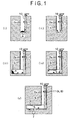
- the construction method according to Claim 1 of the present invention is a method, which is applied to construction of the underground galleries in the stratum disposal site of the waste matter and the mountain tunnels or the like, and in which the air carrying pipeline is arranged in the vertical shaft or the inclined shaft, and by using the air carrying pipeline and a carrying container (a so-called capsule transport line), the carrying-out of the excavation chips from the vertical shaft, the inclined shaft or the underground gallery to the ground, and the carrying-in of the materials and equipment including the spray concrete for the vertical shaft, the inclined shaft or the underground gallery to the underground site are effected (See Fig. 1).
- other paths or other carrying means are also available for the carrying-out of the excavation chips or the carrying-in of the materials and equipment.
- a method of constructing underground galleries by using a vertical shaft or an inclined shaft specifically, a method of constructing underground galleries, wherein the vertical shaft or inclined shaft itself constructed by excavation is used as an air carrying pipeline, and by using the air carrying pipeline, excavation chips from the underground gallery are carried out to the ground or materials and equipment for the underground gallery are carried in to the underground site.
- the air carrying pipeline is also used in the underground galleries for both of the carrying-out of the excavation chips and the carrying-in of the materials and equipment, or alternatively, either of the carrying-out of the excavation chips or the carrying-in of the materials and equipment.
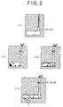
- the construction method according to Claim 2 of the present invention is a method, which is applied to construction of the underground galleries in the stratum disposal site of the waste matter and the mountain tunnels or the like, and in which the air carrying pipeline is constructed in such a manner that the vertical shaft or the inclined shaft for air carrying is constructed by excavation and a lining material and a membrane or the like respectively adapted to bear a strength and an air-tightness are then placed on the inner side wall of the vertical shaft or the inclined shaft, and by using the vertical shaft-and-air carrying pipeline and the carrying container (the so-called capsule transport line), the carrying-out of the excavation chips from the vertical shaft, the inclined shaft or the underground gallery to the ground, and the carrying-in of the materials and equipment including the spray concrete for the vertical shaft, the inclined shaft or the underground gallery to the underground site are effected (See Fig. 2).
- other paths or other carrying means are also available for the carrying-out of the excavation chips or the carrying-in of the materials and equipment in the underground galleries.
- a stratum disposal method of performing stratum disposal of waste matter in an underground disposal space specifically, a stratum disposal method, wherein an air carrying pipeline is arranged in an access vertical shaft or an access inclined shaft extending to an underground gallery, and by using the air carrying pipeline, the waste matter is carried in to the underground gallery for positioning and burying of the waste matter in the disposal space.
- the stratum disposal method according to Claim 3 of the present invention is a method, which is applied to disposal of the waste matter (the so-called overpack) such as radioactive wastes, for instance, by positioning and burying the waste matter, together with the buffer material, in the underground disposal space (a disposal gallery or disposal holes provided for the disposal gallery or the like), and in which the air carrying pipeline is arranged in the access vertical shaft or the access inclined shaft, and by using the air carrying pipeline and the carrying container (the so-called capsule transport line), the carrying-in of the waste matter to the underground gallery is effected (See Fig. 1).
- the air carrying pipeline and an automatic remote control positioning apparatus or the like may be used for the carrying of the waste matter to the disposal space to ensure that the waste matter is positioned and buried, together with the buffer material, in the disposal space.
- a stratum disposal method of performing stratum disposal of waste matter in an underground disposal space specifically, a stratum disposal method, wherein a vertical shaft or an inclined shaft itself constructed by excavation is used as an air carrying pipeline, and by using the air carrying pipeline, the waste matter is carried in to the underground gallery, for positioning and burying of the waste matter in the disposal space.
- the stratum disposal method according to Claim 4 of the present invention is a method, which is applied to disposal of the waste matter (the so-called overpack) such as the radioactive waste, for instance, by positioning and burying the waste matter, together with the buffer material, in the underground disposal space (the disposal gallery or the disposal holes provided for the disposal gallery), and in which the air carrying pipeline is constructed in such a manner that the vertical shaft or the inclined shaft for air carrying is constructed by excavation and a lining material and a membrane or the like respectively adapted to bear a strength and an air-tightness are placed on the inner side wall of the vertical shaft or the inclined shaft, and by using the vertical shaft-and-air carrying pipeline and the carrying container (the so-called capsule transport line), the carrying-in of the waste matter to the underground gallery is effected (See Fig. 2).
- the air carrying pipeline and the automatic remote control positioning apparatus or the like may be used for the carrying of the waste matter to the disposal space to ensure that the waste matter is positioned and buried, together with the buffer material, in the disposal
- the stratum disposal method in the stratum disposal method according to Claim 3 or 4, there is provided the stratum disposal method, wherein a carrying matter obtained by integrating the waste matter and the buffer material together is carried by pneumatic transfer, and is positioned and buried in a disposal space.
- the waste matter itself may be carried by pneumatic transfer or the carrying container with the waste matter stored therein may be also carried by pneumatic transfer
- the waste matter and the buffer material are stored in an integrating container, and the pneumatic transfer of the integrating container is effected with the integrating container stored in the carrying container or with the integrating container as the carrying container to position and bury the integrating container in the disposal space.
- the stratum disposal method in the stratum disposal method according to Claim 1, 2, 3, 4 or 5, there is provided the stratum disposal method, wherein the air carrying pipeline has, at a lower part, an air valve which permits the inflow of air into the pipeline and checks the outflow of air to the outside of the pipeline.
- a pneumatic transfer system while use is made of systems such as a suction system, wherein an exhaust device is arranged at an upper part of the air carrying pipeline, a press-in system, wherein an exhaust device is arranged at a lower part of the air carrying pipeline, and a system, wherein the exhaust device is arranged at both of the upper and lower parts of the air carrying pipeline, a pneumatic transfer system having the air valve of check valve type at the lower part of the air carrying pipeline is effective in performing supply of air into the pipeline or ventilation of the underground facilities and the tunnels efficiently in a valve opened condition, and also enables a pneumatic damper effect to be obtained in a valve closed condition.
- the damper effect is expected to be active, with the result that the safety is secured.
- the vertical shaft is a shaft constructed in a vertical position by excavation
- the inclined shaft includes a linear-shaped or partly curved shaft constructed in an inclined position by excavation.
- the pneumatic transfer system is used to carry out and carry in the carrying matter using a difference between pneumatic pressures at the upper and lower sides of the carrying matter, 1 ⁇ it is allowable to dispense with the conventional wire rope so that any restriction by a depth is eliminated to ensure that carrying even to a greater depth is executable, 2 ⁇ a carrying speed may be increased as compared with a conventional wire rope system, 3 ⁇ the transfer system requires only the differential pressure management, leading to an increase in carrying reliability, 4 ⁇ a transfer system mechanism is simple, so that high resistance to troubles is obtainable, and maintenance or management thereof also becomes facilitated, and 5 ⁇ there is no necessity of a precise carrying machine, resulting in an increase in economical efficiency.
- the carrying-out of the excavation chips or the like and the carrying-in of the materials and equipment or the like in construction of the stratum disposal site and the mountain tunnels or the like, and the carrying-in of the waste mater in the stratum disposal site and the positioning of the waste matter and the buffer material in the stratum disposal site may be effected safely, quickly and reliably at low cost.
- the air carrying pipeline is also serviceable as a ventilating vertical shaft, and thus requires no arrangement of other ventilation systems, leading to an increase in economical efficiency.
- the air carrying pipeline having the strength and the air-tightness may be constructed easily only by placing the lining material and the membrane or the like on the inner side wall of the vertical shaft or the like, and 2 ⁇ a compact transfer system may be given to ensure that a diameter reduction of the vertical shaft or the like is attainable.
- the carrying container is put to practical use in the stratum disposal of the radioactive waste matter, and the waste matter and the buffer material are integrated together at the ground facilities.
- Fig. 1 shows a construction stage and an operation stage in order when an air carrying pipeline is placed in an access vertical shaft of a stratum disposal site.
- Fig. 2 shows a construction stage and an operation stage in order when an individual vertical shaft is used as the air carrying pipeline.
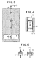
- Fig. 3 shows an outline of a pneumatic transfer system for use in the present invention.
- transfer of the waste matter for positioning may take place also using an automatic remote control positioning apparatus or the like. Or alternatively, it is also allowable to apply the air carrying pipeline 10 to the transfer of the waste matter for positioning in such a manner as to place the air carrying pipeline 10 also in the disposal gallery 3.
- the air carrying pipeline 10 is also serviceable as an exhaust shaft for ventilation of the underground facilities as will be described later, and thus requires no arrangement of other ventilation systems, leading to an increase in economical efficiency.
- the transfer of the waste matter for positioning in this case may take place also using the automatic remote control positioning apparatus or the like. Or alternatively, it is also allowable to apply the air carrying pipeline 10 to the transfer of the waste matter for positioning in such a manner as to place the air carrying pipeline 10 also in the disposal gallery 3.
- the air carrying pipeline having the strength and the air-tightness may be constructed only by placing the lining material and the membrane on the inner side wall of the vertical shaft.
- the compact transfer system may be given to ensure that a vertical shaft diameter reduction is attainable. The above advantages lead to an increase in economical efficiency.
- the vertical shaft 12 itself is also serviceable as the exhaust shaft for ventilation of the underground facilities as will be described later, and thus requires no arrangement of other ventilation systems, leading to an increase in economical efficiency.
- Figs. 3 to 5 show an embodiment of the air carrying pipeline 13 applied to the above case [B], and the air carrying pipeline 13 having the strength and the air-tightness is constructed by giving a lining material (such as concrete) 14 and a membrane (such as a stainless steel plate) 15 to an inner wall surface of the individual vertical shaft 12 constructed by excavation of a bedrock.
- a lining material such as concrete
- a membrane such as a stainless steel plate
- the air carrying pipeline 10 applied to the above case [A] is constructed by connecting steel pipe units together.
- An exhaust device 16 such as a blower is placed at an upper part of the air carrying pipeline 13 (or 10), and an air valve 17 is provided at a lower part thereof to control a carrying speed (an ascend speed and a descend speed) of the carrying container 11 by managing a difference between pneumatic pressures at the upper and lower sides of the carrying container 11 in such a manner as to effect the exhaust of air through the upper part and the suction of air through the lower part.
- the illustrated embodiment employs the negative pressure suction system
- the present invention is not limited to the above system, and a positive pressure press-in system with the blower or the like arranged at the lower part or a system with the blower or the like arranged at both of the upper and lower parts is also available.
- the air valve 17 is a kind of check valve and has a structure in which an opened condition is automatically given by the flow of air created at the time of carrying to ensure that the inflow of air from the underground facilities to the air carrying pipeline 13 is permitted, while a closed condition is automatically given by the reverse flow of air created at the time of system troubles or spontaneous falling to ensure that the outflow of air from the air carrying pipeline 13 to the underground facilities is prevented.
- the air valve 17 is opened automatically to effect the suction of air in the underground facilities for the exhaust to the ground, thereby enabling the ventilation in an administrative area of the underground facilities, as shown in Fig. 6.
- the individual vertical shaft 12 for carrying is also serviceable as the ventilating vertical shaft, and thus requires no arrangement of other ventilating systems, leading to an increase in economical efficiency.
- the air carrying pipeline 13 has also, at the upper and lower parts, detachable devices 18.
- the upper and lower parts of the air carrying pipeline 13 are respectively composed of steel pipes, and loading and unloading of the carrying container 11 or the like are effected in such a manner as to horizontally slide movable steel pipes for the above steel pipes using a traverse carriage and so on.
- Fig. 7 shows an embodiment of a carrying container-11 carrying-in process.
- the carrying container 11 with the materials and equipment, the waste matter or the buffer material or the like stored therein is inserted into the upper detachable device 18, and this upper detachable device 18 is then set at the upper part of the air carrying pipeline 13.
- the exhaust device 16 is operated to carry the carrying container 11 to the underground site, while managing the difference between the pneumatic pressures at the upper and lower sides of the carrying container 11.
- the lower detachable device 18 is detached from the lower part of the air carrying pipeline 13 to take out the carrying container 11 from the lower detachable device 18.
- Figs. 8 to 10 show various kinds of carrying matter forms.
- Figs. 8 and 9 show a case where the carrying of the waste matter A (overpack) and the buffer material (bentonite-contained mixed soil) B that are integrated together is effected, and the integrated waste matter A and buffer material B are positioned and buried.
- the waste matter A and the buffer material B are stored in an integrating container 20 at the ground facilities, and the carrying of the integrating container 20 is effected with the integrating container 20 further inserted into the carrying container 11.
- the waste matter A and the buffer material B are stored in the integrating container 20 at the ground facilities, and the carrying of the integrating container 20 is effected as it is with the integrating container 20 as the carrying container 11.
- the carrying matter form is not limited to the above forms, and it is also allowable to carry the waste matter A as it is without using the carrying container, as shown in Fig. 10. Further, the carrying of the waste matter A may be also effected with the waste matter A stored in the carrying container 11. In this case, the carrying of the buffer material B is effected separately with the buffer material B stored in the carrying container 11.
- spacers 21 such as wheels mounted to an outer circumference of the carrying container 11 as shown in Fig. 8 are effective in preventing the membrane of the air carrying pipeline from being damaged by the container during the carrying, leading to an increase in pneumatic transfer system durability. Further, a seal material is provided on the outer circumference of the carrying container 11 as needed.
- the waste matter A and the buffer material B individually by pneumatic transfer, without being limited to the carrying of the waste matter A and the buffer material B that are integrated together.
- the carrying of the waste matter A is effected as it is as shown in Fig. 10
- a further inside diameter reduction of the individual vertical shaft 12 or the like is obtainable.
- the carrying of the waste matter A and the buffer material B is effected with an upper buffer material B 1 , the waste matter A and a lower buffer material B 2 stored in three pieces of carrying containers 11 respectively, for instance, as shown in Fig. 12.
- the positioning is effected in such a manner that the lower buffer material B 2 is firstly positioned in the disposal hole 7, the waste material A is then positioned, and the upper buffer material B 1 is then positioned on the waste matter A.
- the carrying of the excavation chips or the materials and equipment including the spray concrete may be effected with the excavation chips or the materials and equipment stored in the carrying container 11.
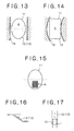
- Fig. 13 shows an embodiment of a pneumatic transfer system that is independent of a vertical accuracy of the vertical shaft 12. It is possible to attain the carrying independent of an accuracy of excavation to a perpendicularity of the vertical shaft in such a manner as to provide a structure in which the carrying matter such as the carrying container 11 and the waste matter A makes contact with the membrane 15 around the carrying matter only through a plane including a section perpendicular to the vertical shaft 12, in other words, form the carrying matter in a spherical or oval shape, for instance.
- the carrying of the carrying matter may be effected safely in such a manner as to form the carrying matter in the spherical or oval shape or the like.
- the increased stability during the carrying and at the time of landing is provided by locating the center of gravity of the carrying matter at a position lower than a point of contact of the carrying matter with the membrane in such a manner as to place the waste matter A at the lower part of the carrying container 11, as shown in Fig. 15.
- the individual vertical shaft 12 for carrying need not extending perpendicularly, and may be an inclined or partially curved shaft (with a curve whose radius of curvature is as much as permitting passage of the carrying container or the like), as shown in Fig. 16.
- the carrying in a spontaneous fall condition may be also effected.
- a method of carrying in the spontaneous fall condition it is also allowable to increase the damper effect in such a manner as to fill the vertical shaft with liquid such as water.
- the vertical shaft damper effect provides a high failsafe against the fall of the carrying matter, the further increased safety may be provided by gradually reducing the lower part diameter of the vertical shaft 12, as shown in Fig. 17.
- the differential pressure management applied to a case where the carrying matter is lightweight (the carrying device is capable of being lifted with the atmospheric pressure) is limited to the suction system (with the negative pressure).
- the differential pressure management applied to a case where the carrying matter is heavy is limited to the press-in system (with the positive pressure).
- the present invention is not limited to the stratum disposal site, and it is allowable to apply the pneumatic transfer system of the present invention also to construction of the tunnels such as the mountain tunnels. While the stratum disposal of the radioactive waste matter in the mode of positioning with the disposal holes has been described, it is to be understood that the present invention is not limited to the above positioning mode, and it is, of course, allowable to apply the present invention to other positioning modes. It is also to be understood that the present invention is not limited to the burying disposal of radioactive waste matter, and it is also allowable to apply the present invention to the burying disposal of other waste matters.
- the present invention has the above arrangements, and therefore, the following effects may be obtained.
Landscapes
- Engineering & Computer Science (AREA)
- Mining & Mineral Resources (AREA)
- Geology (AREA)
- Life Sciences & Earth Sciences (AREA)
- General Life Sciences & Earth Sciences (AREA)
- Geochemistry & Mineralogy (AREA)
- Environmental & Geological Engineering (AREA)
- Physics & Mathematics (AREA)
- General Engineering & Computer Science (AREA)
- High Energy & Nuclear Physics (AREA)
- Mechanical Engineering (AREA)
- Processing Of Solid Wastes (AREA)
- Lining And Supports For Tunnels (AREA)
- Refuse Collection And Transfer (AREA)
Applications Claiming Priority (3)
| Application Number | Priority Date | Filing Date | Title |
|---|---|---|---|
| JP2001344537 | 2001-11-09 | ||
| JP2001344537A JP3945225B2 (ja) | 2001-11-09 | 2001-11-09 | 空気搬送システムによる地層処分方法 |
| PCT/JP2002/011672 WO2003040523A1 (fr) | 2001-11-09 | 2002-11-08 | Procede de construction de galeries souterraines par utilisation d'un systeme de transfert pneumatique, et procede de stockage permanent de strate |
Publications (2)
| Publication Number | Publication Date |
|---|---|
| EP1443177A1 true EP1443177A1 (de) | 2004-08-04 |
| EP1443177A4 EP1443177A4 (de) | 2005-04-13 |
Family
ID=19158050
Family Applications (1)
| Application Number | Title | Priority Date | Filing Date |
|---|---|---|---|
| EP02775513A Withdrawn EP1443177A4 (de) | 2001-11-09 | 2002-11-08 | Verfahren zur herstellung unterirdischer stollen durch verwendung eines pneumatischen transfersystems und zwischenschichtentsorgungsverfahren |
Country Status (5)
| Country | Link |
|---|---|
| US (1) | US7063657B2 (de) |
| EP (1) | EP1443177A4 (de) |
| JP (1) | JP3945225B2 (de) |
| CA (1) | CA2466208A1 (de) |
| WO (1) | WO2003040523A1 (de) |
Cited By (9)
| Publication number | Priority date | Publication date | Assignee | Title |
|---|---|---|---|---|
| WO2010023650A1 (en) * | 2008-09-01 | 2010-03-04 | Avner And Yossi Civil Engineering And Projects Ltd. | Method and arrangement for detection and destruction of tunnels |
| WO2019218085A1 (en) * | 2018-05-17 | 2019-11-21 | Hydrostor Inc. | A hydrostatically compensated compressed gas energy storage system |
| US10760739B2 (en) | 2017-02-01 | 2020-09-01 | Hydrostor Inc. | Hydrostatically compensated compressed gas energy storage system |
| US11274792B2 (en) | 2017-03-09 | 2022-03-15 | Hydrostor Inc. | Thermal storage in pressurized fluid for compressed air energy storage systems |
| US11519393B2 (en) | 2019-01-15 | 2022-12-06 | Hydrostor Inc. | Compressed gas energy storage system |
| US11835023B2 (en) | 2019-02-27 | 2023-12-05 | Hydrostor Inc. | Hydrostatically compensated caes system having an elevated compensation liquid reservoir |
| US12276462B2 (en) | 2019-02-08 | 2025-04-15 | Hydrostor Inc. | Three section configuration for compressed air energy storage systems |
| US12297056B2 (en) | 2018-05-17 | 2025-05-13 | Hydrostor Inc. | Construction elements and maintenance methods for compressed air energy storage systems |
| US12584589B2 (en) | 2021-04-29 | 2026-03-24 | Hydrostor Inc. | Inhibiting the champagne effect in hydrostatically compensated CAES systems |
Families Citing this family (19)
| Publication number | Priority date | Publication date | Assignee | Title |
|---|---|---|---|---|
| AU2004207151B2 (en) * | 2003-01-27 | 2008-12-04 | Redpath Canada Limited | Method and apparatus for raise bore drilling and lining a bore hole |
| RU2004105195A (ru) * | 2004-02-25 | 2005-08-10 | Лев Николаевич Максимов (RU) | Способ подземного хранения экологически опасных веществ и устройство для его осуществления |
| US7661910B2 (en) * | 2006-05-18 | 2010-02-16 | Ross Guenther | Hydraulic elevation apparatus and method |
| US8104998B2 (en) * | 2006-05-18 | 2012-01-31 | Ross Guenther | Hydraulic elevation apparatus and method |
| US20120096702A1 (en) * | 2007-09-14 | 2012-04-26 | Alan Kingsley | Automated construction system |
| JP5331993B2 (ja) * | 2008-10-03 | 2013-10-30 | 鹿島建設株式会社 | 廃棄物の空気カプセル輸送方法 |
| EP2449213B1 (de) * | 2009-06-30 | 2021-10-13 | Technological Resources PTY. Limited | Unterirdischer bergbau |
| JP6323663B2 (ja) * | 2014-03-13 | 2018-05-16 | 株式会社大林組 | 人工バリア構造及びオーバーパックの回収方法 |
| JP6500333B2 (ja) * | 2014-03-13 | 2019-04-17 | 株式会社大林組 | 人工バリア構造及びオーバーパックの回収方法 |
| CN104141500B (zh) * | 2014-04-11 | 2016-08-24 | 中国水利水电第十一工程局有限公司 | 一种板结砂砾石地层洞室施工方法 |
| JP6454987B2 (ja) * | 2014-06-05 | 2019-01-23 | 株式会社大林組 | 廃棄体の回収方法 |
| JP6180060B1 (ja) * | 2016-11-10 | 2017-08-16 | 有限会社モリ | 廃棄物の処分方法 |
| CN108439907A (zh) * | 2018-04-27 | 2018-08-24 | 天津城建大学 | 一种水泥基渣土混凝土的制备工艺 |
| CN108561184B (zh) * | 2018-04-30 | 2019-04-19 | 西安科技大学 | 一种建造在矿井井下的能源储库群及其建造方法 |
| US10878972B2 (en) * | 2019-02-21 | 2020-12-29 | Deep Isolation, Inc. | Hazardous material repository systems and methods |
| CN113266124A (zh) * | 2021-04-16 | 2021-08-17 | 华东勘测设计院(福建)有限公司 | 一种排烟竖井结构及其施工方法 |
| CN117005909B (zh) * | 2023-08-21 | 2025-08-19 | 中国矿业大学 | 一种煤基固废处置与压缩空气储能方法 |
| WO2025085394A1 (en) * | 2023-10-15 | 2025-04-24 | David Hussey | Borehole pneumatic elevator for underground delivery system |
| KR102665799B1 (ko) * | 2023-12-05 | 2024-05-17 | 한국원자력환경공단 | 심층처분시설에 처분된 사용후핵연료의 밀반출 감시시스템 및 방법 |
Family Cites Families (13)
| Publication number | Priority date | Publication date | Assignee | Title |
|---|---|---|---|---|
| US4184792A (en) * | 1976-11-29 | 1980-01-22 | Turnbo August Z | Vacuum-tube mass-transit system |
| SU1151502A1 (en) * | 1978-12-25 | 1985-04-23 | Karagandinskij Polt Institut | Pneumatic mine hoist |
| US4316682A (en) * | 1980-02-25 | 1982-02-23 | Atlantic Richfield Company | Ore carrier |
| FR2526574A1 (fr) * | 1982-05-05 | 1983-11-10 | Commissariat Energie Atomique | Procede d'evacuation de dechets radioactifs et installation geologique pour l'evacuation de ces dechets |
| JPH0631878B2 (ja) * | 1988-11-29 | 1994-04-27 | 三井建設株式会社 | カプセルを大深部地下へ移送する方法 |
| JPH04326954A (ja) * | 1991-04-25 | 1992-11-16 | Mitsui Constr Co Ltd | 建築現場用廃材処理装置 |
| JP2997969B2 (ja) * | 1992-06-16 | 2000-01-11 | 三井造船株式会社 | 地下大深度域における物品輸送システム |
| RU2081327C1 (ru) * | 1992-11-04 | 1997-06-10 | Андрей Степанович Морин | Пневматический подъемник |
| JP3009985B2 (ja) | 1993-10-06 | 2000-02-14 | 住友金属工業株式会社 | トンネル工事用車両の鉛直搬送装置及び鉛直搬送方法 |
| JPH10290968A (ja) * | 1997-04-21 | 1998-11-04 | Ishikawajima Harima Heavy Ind Co Ltd | 廃棄物埋設用遮水緩衝材 |
| JP3418556B2 (ja) * | 1998-07-28 | 2003-06-23 | 住友金属工業株式会社 | カプセル輸送設備 |
| JP3803211B2 (ja) * | 1999-07-26 | 2006-08-02 | 鹿島建設株式会社 | カプセル輸送設備 |
| JP2001158532A (ja) * | 1999-12-02 | 2001-06-12 | Kansai Sekkei Kk | カプセル輸送設備 |
-
2001
- 2001-11-09 JP JP2001344537A patent/JP3945225B2/ja not_active Expired - Fee Related
-
2002
- 2002-11-08 WO PCT/JP2002/011672 patent/WO2003040523A1/ja not_active Ceased
- 2002-11-08 EP EP02775513A patent/EP1443177A4/de not_active Withdrawn
- 2002-11-08 US US10/494,648 patent/US7063657B2/en not_active Expired - Fee Related
- 2002-11-08 CA CA002466208A patent/CA2466208A1/en not_active Abandoned
Non-Patent Citations (2)
| Title |
|---|
| No further relevant documents disclosed * |
| See also references of WO03040523A1 * |
Cited By (18)
| Publication number | Priority date | Publication date | Assignee | Title |
|---|---|---|---|---|
| WO2010023650A1 (en) * | 2008-09-01 | 2010-03-04 | Avner And Yossi Civil Engineering And Projects Ltd. | Method and arrangement for detection and destruction of tunnels |
| US11473724B2 (en) | 2017-02-01 | 2022-10-18 | Hydrostor Inc. | Hydrostatically compensated compressed gas energy storage system |
| US10760739B2 (en) | 2017-02-01 | 2020-09-01 | Hydrostor Inc. | Hydrostatically compensated compressed gas energy storage system |
| US10859207B2 (en) | 2017-02-01 | 2020-12-08 | Hydrostor Inc. | Hydrostatically compensated compressed gas energy storage system |
| US11767950B2 (en) | 2017-02-01 | 2023-09-26 | Hydrostor Inc. | Hydrostatically compensated compressed gas energy storage system |
| US12222068B2 (en) | 2017-03-09 | 2025-02-11 | Hydrostor Inc. | Thermal storage in pressurized fluid for compressed air energy storage systems |
| US11274792B2 (en) | 2017-03-09 | 2022-03-15 | Hydrostor Inc. | Thermal storage in pressurized fluid for compressed air energy storage systems |
| US11644150B2 (en) | 2017-03-09 | 2023-05-09 | Hydrostor Inc. | Thermal storage in pressurized fluid for compressed air energy storage systems |
| US11821584B2 (en) | 2017-03-09 | 2023-11-21 | Hydrostor Inc. | Thermal storage in pressurized fluid for compressed air energy storage systems |
| US20210207771A1 (en) * | 2018-05-17 | 2021-07-08 | Hydrostor Inc. | Hydrostatically compensated compressed gas energy storage system |
| WO2019218085A1 (en) * | 2018-05-17 | 2019-11-21 | Hydrostor Inc. | A hydrostatically compensated compressed gas energy storage system |
| US12297056B2 (en) | 2018-05-17 | 2025-05-13 | Hydrostor Inc. | Construction elements and maintenance methods for compressed air energy storage systems |
| US12366326B2 (en) * | 2018-05-17 | 2025-07-22 | Hydrostor Inc. | Reuse of construction shafts in compressed air energy storage systems |
| US11519393B2 (en) | 2019-01-15 | 2022-12-06 | Hydrostor Inc. | Compressed gas energy storage system |
| US12292037B2 (en) | 2019-01-15 | 2025-05-06 | Hydrostor Inc. | Compressed gas energy storage system |
| US12276462B2 (en) | 2019-02-08 | 2025-04-15 | Hydrostor Inc. | Three section configuration for compressed air energy storage systems |
| US11835023B2 (en) | 2019-02-27 | 2023-12-05 | Hydrostor Inc. | Hydrostatically compensated caes system having an elevated compensation liquid reservoir |
| US12584589B2 (en) | 2021-04-29 | 2026-03-24 | Hydrostor Inc. | Inhibiting the champagne effect in hydrostatically compensated CAES systems |
Also Published As
| Publication number | Publication date |
|---|---|
| WO2003040523A1 (fr) | 2003-05-15 |
| JP2003148097A (ja) | 2003-05-21 |
| CA2466208A1 (en) | 2003-05-15 |
| EP1443177A4 (de) | 2005-04-13 |
| US7063657B2 (en) | 2006-06-20 |
| JP3945225B2 (ja) | 2007-07-18 |
| US20050004416A1 (en) | 2005-01-06 |
Similar Documents
| Publication | Publication Date | Title |
|---|---|---|
| US7063657B2 (en) | Method of constructing underground gallery by using pneumatic transfer system and stratum disposal method | |
| US20120163919A1 (en) | Method for erecting an underground construction | |
| CN114855820A (zh) | 一种异型深基坑多圆环内支撑拆除施工方法 | |
| CN113136887B (zh) | 一种压气干沉井施工工艺 | |
| CN110439590A (zh) | 隧道施工方法 | |
| JPS6229671B2 (de) | ||
| CN210797545U (zh) | 一种桩基钢筋笼接长施工的加固装置 | |
| CN110400649B (zh) | 一种低中水平放射性废物岩洞处置的方法及结构 | |
| CN116838364A (zh) | 一种土压平衡式顶管管内土方接力式倒运方法及运输装置 | |
| CN217632432U (zh) | 向上硬岩掘进装置 | |
| US5746540A (en) | Method of isolating a nuclear reactor or other large structures | |
| CN107860555A (zh) | 一种用于水下垂直发射试验的试验水池 | |
| CN116104121A (zh) | 锚杆基础施工方法 | |
| Pettersson et al. | Final repository for spent nuclear fuel in granite-the KBS-3V concept in Sweden and Finland | |
| Baumgartner et al. | Engineering for a disposal facility using the in-room emplacement method | |
| CN217129589U (zh) | 一种超深竖井浮力与提升机联合提矿系统 | |
| Thorsager et al. | KBS-3H. Summary report of work done during Basic Design | |
| CN216008587U (zh) | 井筒管道布置装置 | |
| CN105378221B (zh) | 使部件或材料移动至矿井钻探系统的高度并且在其高度内移动的方法 | |
| Kosugi et al. | Applicability of pneumatic capsule pipeline to radioactive waste disposal facility | |
| CN112502634A (zh) | 一种基于黄土层的干钻掘进方法及设备 | |
| Kronberg | KBS-3H Preparations, assembly and installation of the Multi Purpose Test | |
| CN220267704U (zh) | 一种适用于暗挖隧道crd法四导洞开挖施工的隧道洞口施工平台 | |
| CN119914352B (zh) | 一种多功能隧道施工辅助设施及其设计方法 | |
| Wang et al. | Pipe Jacking Construction Measures |
Legal Events
| Date | Code | Title | Description |
|---|---|---|---|
| PUAI | Public reference made under article 153(3) epc to a published international application that has entered the european phase |
Free format text: ORIGINAL CODE: 0009012 |
|
| 17P | Request for examination filed |
Effective date: 20040510 |
|
| AK | Designated contracting states |
Kind code of ref document: A1 Designated state(s): AT BE BG CH CY CZ DE DK EE ES FI FR GB GR IE IT LI LU MC NL PT SE SK TR |
|
| A4 | Supplementary search report drawn up and despatched |
Effective date: 20050224 |
|
| RIC1 | Information provided on ipc code assigned before grant |
Ipc: 7G 21F 9/36 B Ipc: 7E 21D 9/13 B Ipc: 7E 21D 1/00 B Ipc: 7G 21F 9/34 B Ipc: 7E 21D 9/12 A Ipc: 7E 21F 17/16 B |
|
| 17Q | First examination report despatched |
Effective date: 20070626 |
|
| STAA | Information on the status of an ep patent application or granted ep patent |
Free format text: STATUS: THE APPLICATION IS DEEMED TO BE WITHDRAWN |
|
| 18D | Application deemed to be withdrawn |
Effective date: 20100601 |