EP1443295B1 - Pistole mit Sperrvorrichtung - Google Patents
Pistole mit Sperrvorrichtung Download PDFInfo
- Publication number
- EP1443295B1 EP1443295B1 EP03450269A EP03450269A EP1443295B1 EP 1443295 B1 EP1443295 B1 EP 1443295B1 EP 03450269 A EP03450269 A EP 03450269A EP 03450269 A EP03450269 A EP 03450269A EP 1443295 B1 EP1443295 B1 EP 1443295B1
- Authority
- EP
- European Patent Office
- Prior art keywords
- pistol
- drive rod
- trigger
- shaft
- blocking
- Prior art date
- Legal status (The legal status is an assumption and is not a legal conclusion. Google has not performed a legal analysis and makes no representation as to the accuracy of the status listed.)
- Expired - Lifetime
Links
- 230000033001 locomotion Effects 0.000 claims description 31
- 230000000903 blocking effect Effects 0.000 claims description 11
- 238000010304 firing Methods 0.000 claims description 6
- 239000002184 metal Substances 0.000 claims description 3
- 241001433879 Camarea Species 0.000 claims 1
- 230000004323 axial length Effects 0.000 claims 1
- 238000007373 indentation Methods 0.000 claims 1
- 239000000463 material Substances 0.000 description 6
- 230000006378 damage Effects 0.000 description 4
- 230000005540 biological transmission Effects 0.000 description 2
- 238000006243 chemical reaction Methods 0.000 description 1
- 238000010276 construction Methods 0.000 description 1
- 230000003993 interaction Effects 0.000 description 1
- 238000004519 manufacturing process Methods 0.000 description 1
Images


Classifications
-
- F—MECHANICAL ENGINEERING; LIGHTING; HEATING; WEAPONS; BLASTING
- F41—WEAPONS
- F41A—FUNCTIONAL FEATURES OR DETAILS COMMON TO BOTH SMALLARMS AND ORDNANCE, e.g. CANNONS; MOUNTINGS FOR SMALLARMS OR ORDNANCE
- F41A17/00—Safety arrangements, e.g. safeties
- F41A17/02—Key-operated safeties
Definitions
- the invention relates to a locking device for a pistol with a trigger, a trigger mechanism and an actuated by this firing pin, hammer or the like.
- the locking device arranged in the handle of the weapon cylinder lock, the lock cylinder is rotatable with a key and a transmission mechanism of the rods , Levers, threads and the like. comprising, whereby a blocking element from a position in which it is outside the path of movement of a part of the trigger mechanism of the gun, can be moved to a position in which it projects into the path of movement of this part.
- a locking device which is provided in the lower part of a rebuilt magazine and pushes a locking pin through aligned recesses in the rear wall of the magazine and the rear wall of the magazine shaft in the movement path of the trigger mechanism or not.
- This device is complicated, expensive and degrades the efficiency of the weapon, since with increased weight, the number of cartridges in the magazine is reduced.
- this device does not really accomplish its purpose, since it is possible to destroy the magazine without damaging the weapon and subsequently using the weapon with a standard magazine.
- Another locking device is from the WO 02/070978 A known to the applicant.
- the cylinder lock and at least parts of the transmission mechanism are arranged behind the magazine shaft.
- a slotted guide with helical movement path is provided, by which the rotary motion of the cylinder lock is converted into a linear movement, which is transmitted via a rod to a blocking element which, depending on the position of the cylinder lock, the trigger mechanism locks or releases.
- This device works reliably and can not be disabled by unauthorized persons without damaging the weapon. However, it has been shown that it is possible by targeted damage to the weapon to disable the locking device without significantly reducing the functionality of the weapon. Although it is no longer possible to possess such a repaired pistol unsuspicious or even bring in the (legal) traffic, but it can be used illegally. It is necessary to saw in the area of the rotary rod to the back of the handle and so cut the rotary rod. In addition, the slide guide is expensive to manufacture and in need of care.
- the actuating rod transmits the blocking movement or release movement only by rotation and that it is preferably over at least substantially its entire length surrounded by a freely rotatable against her, loose-fitting shell of resistant material, preferably hard metal.
- a freely rotatable against her, loose-fitting shell of resistant material preferably hard metal.
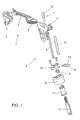
- a locking device according to the invention is shown in an exploded view.
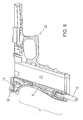
- the entire device is in the assembled state in the grip of a gun 22 behind the magazine shaft 21, this is already out of the WO 02/070978 A whose Fig. 1 in the present application as Fig. 8 is included, known and needs no further explanation here.
- FIG. 8 From the Fig. 8 the position of a device 1 according to the invention in a gun 22 can be seen, although the device shown there corresponds to the prior art.
- This figure is also a nose 23 of a firing pin 17 ( Fig. 2 ) in contact with the associated actuator 24 of the trigger mechanism 2 ( Fig. 1 ).
- a trigger mechanism 2 for a gun 22 has a trigger 3 (trigger guard) and a trigger slide 4.
- a control block 5 the withdrawal movement, reinforced by a trigger spring 6 in the clamping movement and the release movement for a firing pin 17 is implemented.
- This mechanism has been known for some time and has also proven itself. The invention will be explained below with reference to this mechanism, without being limited to use with this mechanism.
- a blocking shaft 7 is now rotatably arranged in the region of the withdrawal movement of the trigger rod 4.
- the locking shaft 7 has at its lower end a receptacle for a drive rod 8, with which it is rotatably connected.
- the upper end of the locking shaft 7 carries a kind of cam 19, for example in the form of a semicircle.
- the other, lower, end of the drive rod 8 is inserted in the receptacle of a Anschlagstükkes 9, which is rotatably mounted in the recess of a lock receptacle 10.
- the lower end face of the lock receptacle 10 is formed substantially flush with the bottom of the handle of the gun and has a receptacle for a rotor 11 which can be rotated by a matching key 12 in the lock receptacle 10.
- the locking shaft 7 has at its upper end a cam-like training 19, which will come back to below.
- the stop piece 9 has, offset from each other in height, two cam-like discs, of which the lower of the height is still in the lock holder 10, while the upper is arranged above.
- the lower cam cooperates with stops in the lock receptacle and limits the rotation of the stop piece and thus the key and the lock shaft.
- the upper cam is located in a recess of an indicator 13 and depending on the angular position of the stop piece, a signal edge 14 of the indicator 13 is removed from the axis of rotation of the stop piece or attracted to him.
- a sleeve 16 loosely surrounding it is arranged, which preferably consists of extremely resistant material, for example hard metal, as will be explained in the following.
- Fig. 2 shows the assembled device of the Fig. 1 and in addition to this, a striker 17 and, indicated in the area of the indicator 13, the casing of a handle piece 18.
- Fig. 12 illustrates the locking device 1 according to the invention in the locked position, a position in which the full part of the cam portion 19 of the locking shaft. 7 is directed to a projection or a shoulder 20 of the slide valve 4 and prevents any movement of the trigger slide 4 in the withdrawal direction. This is especially the top view in Fig. 2 to be taken clearly.
- the sleeve 16 which sits loosely on the drive rod 8, now has the purpose when in the area between the indicator 13 and the (not shown) closure, as far as the sleeve 16, the weapon imprints to destroy the drive rod or in their releasing position to fix, so he pushes with the saw on the sleeve 16 and rotates them freely with each sawing movement over the drive rod 8, without being able to saw through them.
- the sleeve 16 can destroy and with it the drive rod 8.
- the free mobility of the sleeve 16 to the drive rod 8 is in the side elevation of Fig. 2 indicated by the circular arrow F.
- the Fig. 3 shows this mechanism in the same views as the Fig. 2 but with the locking device in the open, unlocked position.
- the difference can be seen in particular in the plan view, where the distance between the shoulder 20 of the trigger slide 4 and the cam portion 19 of the locking shaft 7 can be seen. This distance is sufficient to tension when releasing the trigger movement of the trigger slide 4, the pistol, release the firing pin and so to release the shot.
- the indicator 14 is in the in Fig. 3 shown completely retracted inside the handle, in Fig. 2 , in the locked position, the display surface 14 protrudes significantly over the surrounding surface of the handle 18, so that even in the dark only by the Holding the gun on the handle can be detected whether the locking mechanism is in the locked or the open position.
- the Fig. 4 shows the device of Fig. 3 , wherein the locking device 1 is again in the open position, but it is deducted the trigger mechanism, the trigger slide 4 in its rearmost position, the firing pin 17 just released.
- the trigger slide 4 has enough space even in its rearmost position so as not to collide with the flattened side of the cam portion 19 of the locking shaft 7, so that the functionality of the weapon is completely given.
- FIGS. 5, 6 and 7 show details of the drive rod 8, namely in particular their storage on the one hand in the locking shaft 7, on the other hand in the stop piece. 9
- the Fig. 6 shows a section along the line VI-VI of Fig. 5 , This area is not only polygonal, but also spherical, so that the inclination of the axis of the drive rod 8 with respect to the axis of rotation of the stop piece 9 does not matter. In addition, an axial displaceability is ensured by the polygonal cylindrical receptacle in the stop piece 9.
- the drive rod 8, the torque or rotation of the stop piece 9 transmits to the locking element 7, in the illustrated embodiment of Fig. 1 on both ends of a hexagon transformed or machined area.
- these areas are formed in sections through the axis of spherical, so that even when not aligned axis rotational movements can be transmitted. It is the same or a similar shape as is the case with hex wrenches, which allow the turning of corresponding Allen screws without the need to align the axes.
- Fig. 6 the polygonal-cylindrical shape of the receptacle is illustrated in the stop piece 9
- Fig. 7 the main emphasis is placed on the polygonal-spherical nature of the end of the drive rod 8.
- the invention is not limited to the illustrated embodiment, but may be variously modified. It is essential that the movement between the locked position and the open position of the rotary movement of the key to the movement of the actual locking element, in the embodiment shown, the locking shaft 7, pure rotational movements, through the complicated and vulnerable implementations of the rotational movement in a linear movement , In particular, a conversion of the movement about an axis in an axial movement, are avoided.
- the arrangement of the sleeve 16 as a Aufsägeschutz is a valuable design, which ensures in a simple and extremely reliable manner that manipulation of the locking device is possible only after extensive destruction of the weapon.
Landscapes
- Engineering & Computer Science (AREA)
- General Engineering & Computer Science (AREA)
- Toys (AREA)
- Portable Nailing Machines And Staplers (AREA)
Description
- Die Erfindung betrifft eine Sperrvorrichtung für eine Pistole mit einem Abzug, einem Abzugsmechanismus und einem durch diesen betätigten Schlagbolzen, Hammer od.dgl., wobei die Sperrvorrichtung ein im Griff der Waffe angeordnetes Zylinderschloß, dessen Schließzylinder mit einem Schlüssel verdrehbar ist und einen Übertragungsmechanismus der Stangen, Hebeln, Gewinde u.dgl. aufweist, umfaßt, womit ein Sperrelement von einer Lage, in der es sich außerhalb der Bewegungsbahn eines Teiles des Abzugsmechanismus der Pistole befindet, in eine Lage bewegt werden kann, in der es in die Bewegungsbahn dieses Teiles ragt.
- Aus der
DE 89 04 112 U ist eine Sperrvorrichtung bekannt, die im unteren Teil eines umgebauten Magazins vorgesehen ist und einen Sperrbolzen durch fluchtende Ausnehmungen in der hinteren Wand des Magazins und der hinteren Wand des Magazinschachtes in die Bewegungsbahn des Abzugsmechanismus schiebt oder auch nicht. Diese Vorrichtung ist kompliziert, teuer und die Funktionstüchtigkeit der Waffe herabsetzend, da bei erhöhtem Gewicht die Anzahl der Patronen im Magazin reduziert wird. Zu guter Letzt erfüllt diese Vorrichtung ihren Zweck nicht wirklich, da es möglich ist, das Magazin zu zerstören, ohne dabei die Waffe zu beschädigen und in der Folge die Waffe mit einem normalen Magazin zu verwenden. - Eine andere Sperrvorrichtung ist aus der
WO 02/070978 A - Diese Vorrichtung arbeitet zuverlässig und kann durch Unbefugte ohne Beschädigung der Waffe nicht deaktiviert werden. Es hat sich aber gezeigt, dass es durch zielgerichtete Beschädigung der Waffe möglich ist, die Sperrvorrichtung zu deaktivieren, ohne die Funktionalität der Waffe entscheidend zu mindern. Es ist zwar nicht mehr möglich, eine so reparierte Pistole unverdächtig zu besitzen oder gar in den (legalen) Verkehr zu bringen, doch kann sie illegalerweise verwendet werden. Es ist dazu notwendig, im Bereich der Drehstange den Rücken des Griffes anzusägen und so die Drehstange zu durchtrennen. Dazu kommt, dass die Kulissenführung aufwendig in der Herstellung und pflegebedürftig ist.
- Es ist das Ziel der vorliegenden Erfindung, diese Probleme zu beheben und eine weiter verbesserte, insbesondere nicht ohne auffällige Zerstörungen manipulierbare Sperrvorrichtung für Pistolen zu schaffen.
- Erfindungsgemäß werden diese Ziele dadurch erreicht, dass die Betätigungsstange die Sperrbewegung bzw. Freigabebewegung nur durch Drehung überträgt und dass sie bevorzugt über zumindest im wesentlichen ihre ganzen Länge von einer ihr gegenüber frei drehbaren, lose sitzenden Hülle aus widerstandsfähigem Material, bevorzugt Hartmetall, umgeben ist. Auf diese Weise vermeidet man alle aufwendigen und anfälligen getriebeartigen Vorrichtungen, die die Drehbewegung des Schlüssels in eine translatorische Bewegung umsetzten. Darüber hinaus ist es bei Versuchen, die Betätigungsstange abzusägen, nicht mehr möglich, bis zu ihr zu kommen, da sich beim Sägen das Hartmetallröhrchen mit der Sägebewegung mitdreht, ohne beschädigt zu werden. So kann die Sperrvorrichtung nicht mehr durch eine unauffällige Beschädigung der äußeren Rückwand des Griffes außer Betrieb genommen werden.
- Die Erfindung ist in der Zeichnung näher erläutert. Dabei zeigt
- die
Fig. 1 eine erfindungsgemäße Sperrvorrichtung in einer Explosionsskizze, - die
Fig. 2 die Vorrichtung derFig. 1 zusammenbaut und in Abzugsmechanismus eine Pistole integriert in gesperrter Lage, - die
Fig. 3 die Vorrichtung derFig. 2 in gleicher Ansicht, aber in freigegebener Lage, - die
Fig. 4 die Ansicht derFig. 3 , aber mit abgezogenem Abzugsbügel, - die
Fig. 5, 6 und 7 Details und - die
Fig. 8 eine schematische Gesamtansicht. - Aus
Fig. 1 ist eine erfindungsgemäße Sperrvorrichtung in einer Explosionsskizze dargestellt. Die gesamte Vorrichtung befindet sich im zusammengebauten Zustand im Griff einer Pistole 22 hinter dem Magazinschacht 21, dies ist bereits aus derWO 02/070978 A Fig. 1 in der vorliegenden Anmeldung alsFig. 8 enthalten ist, bekannt und benötigt hier keine weitere Erläuterung mehr. - Aus der
Fig. 8 ist die Lage einer erfindungsgemäßen Vorrichtung 1 in einer Pistole 22 ersichtlich, wenn auch die dort gezeigte Vorrichtung dem Stand der Technik entspricht. In dieser Figur ist auch eine Nase 23 eines Schlagbolzens 17 (Fig. 2 ) im Kontakt mit dem zugehörigen Betätigungsorgan 24 des Abzugsmechanismus 2 (Fig. 1 ) dargestellt. - Der Aufbau der in ihrer Gesamtheit mit 1 bezeichneten Vorrichtung ist folgender: Ein Abzugsmechanismus 2 für eine Pistole 22 weist ein Züngel 3 (Abzugsbügel) und einen Abzugsschieber 4 auf. In einem Steuerblock 5 wird die Abzugsbewegung, verstärkt durch eine Abzugsfeder 6 in die Spannbewegung und die Freigabebewegung für einen Schlagbolzen 17 umgesetzt. Dieser Mechanismus ist seit längerem bekannt und hat sich auch bewährt. Die Erfindung wird im folgenden anhand dieses Mechanismus erläutert, ohne dass sie auf die Verwendung mit diesem Mechanismus beschränkt wäre. Erfindungsgemäß ist nun im Bereich der Abzugsbewegung der Abzugstange 4 eine Sperrwelle 7 drehbar angeordnet. Die Sperrwelle 7 weist an ihrem unteren Ende eine Aufnahme für eine Antriebsstange 8 auf, mit der sie drehfest verbunden ist. Das obere Ende der Sperrwelle 7 trägt eine Art Nockenscheibe 19, beispielsweise in Form eines Halbkreises.
- Das andere, untere, Ende der Antriebsstange 8 steckt in der Aufnahme eines Anschlagstükkes 9, das in der Ausnehmung einer Schloßaufnahme 10 drehbar gelagert ist. Die untere Stirnfläche der Schloßaufnahme 10 ist im wesentlichen fluchtend mit dem Boden des Griffes der Pistole ausgebildet und hat eine Aufnahme für einen Rotor 11, der durch einen passenden Schlüssel 12 in der Schloßaufnahme 10 verdreht werden kann.
- Beim Verdrehen des Schlüssels 12 dreht sich nicht nur der Rotor 11 und das Anschlagstück 9, sondern auch die Antriebstange 8 und in konsequenter Weise die Sperrwelle 7 gleichermaßen mit. Die Sperrwelle 7 hat an ihrem oberen Ende eine nockenartige Ausbildung 19, auf die weiter unten noch zurückgekommen wird.
- Das Anschlagstück 9 weist, in der Höhe zueinander versetzt, zwei nockenartige Scheiben auf, von denen sich die untere der Höhe nach noch in der Schloßaufnahme 10 befindet, während die obere darüber angeordnet ist. Die untere Nockenscheibe wirkt mit Anschlägen in der Schloßaufnahme zusammen und begrenzt die Verdrehung des Anschlagstückes und damit des Schlüssels und der Sperrwelle. Die obere Nockenscheibe liegt in einer Ausnehmung eines Anzeigers 13 und je nach Winkellage des Anschlagstückes wird eine Signalkante 14 des Anzeigers 13 von der Drehachse des Anschlagstückes entfernt oder zu ihm hingezogen.
- Die Führung des Anzeigers 13 und die axiale Sicherung des Anschlagstückes 9 übernimmt eine Schloßkappe 15, die passend mit der Schloßaufnahme 10 verschraubt ist.
- Über dem größten Teil der Länge der Antriebstange 8 ist eine sie locker umgebende Hülse 16 angeordnet, die bevorzugt aus extrem widerstandsfähigen Material, beispielsweise Hartmetall, besteht, wie in der Folge noch zu erläutern sein wird.
- Die
Fig. 2 zeigt die zusammengebaute Vorrichtung derFig. 1 und zusätzlich dazu einen Schlagbolzen 17 und, im Bereich des Anzeigers 13 angedeutet, die Hülle eines Griffstükkes 18. Die Fig. 12 stellt die erfindungsgemäße Sperrvorrichtung 1 in der gesperrten Position dar, eine Position, bei der der volle Teil des Nockenabschnittes 19 der Sperrwelle 7 zu einem Vorsprung bzw. einer Schulter 20 des Zugschiebers 4 gerichtet ist und jede Bewegung des Abzugschiebers 4 in Abzugsrichtung verhindert. Dies ist insbesondere aus der Draufsicht inFig. 2 deutlich zu entnehmen. - Die Hülse 16, die locker über der Antriebsstange 8 sitzt, hat nun den Zweck, wenn im Bereich zwischen dem Anzeiger 13 und dem (nicht dargestellten) Verschluß, soweit reicht die Hülse 16, die Waffe aufsägt, um die Antriebstange zu zerstören oder in ihrer freigebenden Position zu fixieren, so stößt er mit der Säge auf die Hülse 16 und dreht diese bei jeder Sägebewegung frei über der Antriebstange 8, ohne sie dabei durchsägen zu können. Dies wird einerseits durch das Freie aufgefädelt sein, der Hülse 16 auf der Antriebstange 8 bewirkt, andererseits dadurch, dass die Hülse 16 bevorzugt aus extrem harten Material besteht. Man erreicht damit einen Schutz gegen Manipulation und Mißbrauch, der nur dadurch zu beseitigen ist, dass die Waffe im hinteren Bereich des Griffes großflächig zerstört wird, dass man mit einer Zange, einem Bolzenschneider od.dgl. die Hülse 16 zerstören kann und mit ihr auch die Antriebstange 8. Die freie Beweglichkeit der Hülse 16 um die Antriebstange 8 ist im Seitenriß der
Fig. 2 durch den Kreispfeil F angedeutet. - Die
Fig. 3 zeigt diesen Mechanismus in den gleichen Ansichten wie dieFig. 2 , allerdings mit der Sperrvorrichtung in der offenen, ungesperrten Position. - Der Unterschied ist insbesondere in der Draufsicht zu erkennen, wo der Abstand zwischen der Schulter 20 des Abzugschiebers 4 und dem Nockenabschnitt 19 der Sperrwelle 7 erkennbar ist. Dieser Abstand ist ausreichend, um beim Vollführen der Abzugsbewegung des Abzugschiebers 4 die Pistole zu spannen, den Schlagbolzen freizugeben und so den Schuß zu lösen.
- Der Anzeiger 14 ist in der in
Fig. 3 dargestellten Lage zur Gänze ins Innere des Griffes zurückgezogen, inFig. 2 , in der gesperrten Lage ragt die Anzeigefläche 14 deutlich über die umgebende Oberfläche des Griffstückes 18 vor, so dass auch im Finstern nur durch das Halten der Pistole am Griffstück erkannt werden kann, ob der Sperrmechanismus in der gesperrten oder der offenen Position ist. - Die
Fig. 4 zeigt die Vorrichtung derFig. 3 , wobei die Sperrvorrichtung 1 wiederum in der offenen Position ist, es ist aber der Abzugmechanismus abgezogen, der Abzugschieber 4 in seiner hintersten Position, der Schlagbolzen 17 gerade freigegeben. - Man erkennt im Aufriß, aber auch in der Draufsicht, dass der Abzugschieber 4 auch in seiner hintersten Lage Platz genug hat, um nicht mit der abgeflachten Seite des Nockenabschnittes 19 der Sperrwelle 7 zu kollidieren, so dass die Funktionsfähigkeit der Waffe vollständig gegeben ist.
- Die
Fig. 5, 6 und 7 zeigen Details der Antriebstange 8, nämlich insbesondere ihre Lagerung einerseits in der Sperrwelle 7, andererseits im Anschlagstück 9. - Die
Fig. 6 zeigt einen Schnitt entlang der Linie VI-VI derFig. 5 . Man erkennt die beiden nockenförmigen Scheiben des Anschlagstückes 8 und den zu einem Sechseck umgeformten bzw. bearbeiteten untersten Bereich der Antriebstange 8. Dieser Bereich ist nicht nur polygonal, sondern auch sphärisch ausgebildet, so dass die Schrägstellung der Achse der Antriebstange 8 bezüglich der Drehachse des Anschlagstückes 9 keine Rolle spielt. Darüber hinaus ist durch die polygonal-zylindrische Aufnahme im Anschlagstück 9 auch eine axiale Verschieblichkeit gesichert. - Dazu wird noch näher ausgeführt: Die Antriebstange 8, die Drehmomente bzw. Verdrehungen vom Anschlagstück 9 auf das Sperrelement 7 überträgt, weist im gezeigten Ausführungsbeispiel von
Fig. 1 auf beiden Enden einen zu einem Sechseck umgeformten bzw. bearbeiteten Bereich auf. Zusätzlich zur in jedem Achsschnitt polygonalen Form sind diese Bereiche in Schnitten durch die Achse sphärisch ausgebildet, so dass auch bei nicht fluchtender Achse Drehbewegungen übertragen werden können. Es handelt sich dabei um die gleiche oder eine ähnliche Form, wie sie bei Imbusschlüsseln vorkommt, die das Verdrehen entsprechender Imbusschrauben ermöglichen, ohne dass die Achsen fluchten müssen. Während inFig. 6 die polygonal-zylindrische Form der Aufnahme im Anschlagstück 9 verdeutlicht ist, ist inFig. 7 das Hauptaugenmerk auf die polygonal-sphärische Beschaffenheit des Endes der Antriebstange 8 gelegt. - An Hand des oberen Endes der Antriebstange 8, das mit der Sperrwelle 7 zusammenarbeitet und das gleich ausgebildet ist, wird dieses Zusammenwirken klar. Die polygonalsphärische Ausbildung ist in
Fig. 7 ebenso zu sehen, wie der axiale Freiraum, der die Längenanpassung der Vorrichtung an Toleranzen problemlos ermöglicht. - Die Erfindung ist nicht auf das dargestellte Ausführungsbeispiel beschränkt, sondern kann verschiedentlich abgewandelt werden. Wesentlich ist, dass die Bewegung zwischen der gesperrten Lage und der offenen Lage von der Drehbewegung des Schlüssels bis zur Bewegung des eigentlichen Sperrelementes, im gezeigten Ausführungsbeispiel die Sperrwelle 7, reine Drehbewegungen sind, durch die komplizierte und anfällige Umsetzungen von der Drehbewegung in eine lineare Bewegung, insbesondere eine Umsetzung von der Bewegung um eine Achse in eine axiale Bewegung, vermieden sind. Die Anordnung der Hülse 16 als ein Aufsägeschutz ist eine wertvolle Ausgestaltung, durch die auf einfache und extrem zuverlässige Weise sichergestellt wird, dass eine Manipulation der Sperrvorrichtung erst nach weitgehender Zerstörung der Waffe möglich ist.
- Als Material für den erfindungsgemäßen Sperrmechanismus können alle Materialien verwendet werden, die bei Handfeuerwaffen üblich sind bzw. Materialien, die beim Schloßbau üblich sind, ihre Auswahl stellt für den Fachmann in Kenntnis der Erfindung kein Problem dar.
Claims (6)
- Pistole mit Sperrvorrichtung und mit einem Abzug (3), einem Abzugsmechanismus (4) und einem durch diesen betätigten Schlagbolzen (17), Hammer od.dgl., wobei der Sperrmechanismus ein im Griff der Pistole angeordnetes Zylinderschloß (10, 11) aufweist, dessen Schließzylinder mit einem Schlüssel (12) verdrehbar ist und wobei ein Übertragungsmechanismus (9, 8) ein Sperrelement (7) von einer Lage, in der es sich außerhalb der Bewegungsbahn eines Teiles (20) des Abzugsmechanismus (4) der Pistole befindet, in eine Lage bringt, in der es in die Bewegungsbahn dieses Teiles (20) ragt, wobei das Zylinderschloß und der Übertragungsmechanismus hinter dem Magazinschacht (21) der Pistole (22) angeordnet sind, dadurch gekennzeichnet, dass das Sperrelement (7) und der Übertragungsmechanismus (9, 8) reine Drehbewegungen ausfiihren.
- Pistole nach Anspruch 1, dadurch gekennzeichnet, dass das Sperrelement (7) einen Nockenbereich (19) aufweist, der je nach Winkellage des als Sperrwelle ausgebildeten Sperrelementes in die Bewegungsbahn des Teiles (20) ragt oder nicht.
- Pistole nach Anspruch 1 oder 2, dadurch gekennzeichnet, dass der Übertragungsmechanismus eine Antriebstange (8) umfaßt und dass um die Antriebstange (8) frei drehbar und über einen wesentlichen Teil ihrer axialen Länge reichend, eine Hülse (16) angeordnet ist.
- Pistole nach einem der voranstehenden Ansprüche, dadurch gekennzeichnet, dass die Hülse (16) aus Hartmetall besteht.
- Pistole nach einem der voranstehenden Ansprüche, dadurch gekennzeichnet, dass die Antriebstange (8) an zumindest einem Ende (8') polygonal-sphärisch ausgebildet ist und in einer komplementär ausgebildeten polygonal-zylindrischen Vertiefung (7', 9') des Nachbarteiles, Sperrwelle (7) und/oder Anschlagstück (9) ragt.
- Pistole nach einem der voranstehenden Ansprüche, dadurch gekennzeichnet, dass die Sperrwelle (7) drehbar im Griffstück gelagert ist.
Priority Applications (1)
| Application Number | Priority Date | Filing Date | Title |
|---|---|---|---|
| AT03450269T ATE412870T1 (de) | 2003-01-31 | 2003-12-03 | Pistole mit sperrvorrichtung |
Applications Claiming Priority (2)
| Application Number | Priority Date | Filing Date | Title |
|---|---|---|---|
| AT1522003 | 2003-01-31 | ||
| AT0015203A AT412125B (de) | 2003-01-31 | 2003-01-31 | Sperrvorrichtung für eine pistole |
Publications (2)
| Publication Number | Publication Date |
|---|---|
| EP1443295A1 EP1443295A1 (de) | 2004-08-04 |
| EP1443295B1 true EP1443295B1 (de) | 2008-10-29 |
Family
ID=31192759
Family Applications (1)
| Application Number | Title | Priority Date | Filing Date |
|---|---|---|---|
| EP03450269A Expired - Lifetime EP1443295B1 (de) | 2003-01-31 | 2003-12-03 | Pistole mit Sperrvorrichtung |
Country Status (4)
| Country | Link |
|---|---|
| US (1) | US7051468B2 (de) |
| EP (1) | EP1443295B1 (de) |
| AT (2) | AT412125B (de) |
| DE (1) | DE50310696D1 (de) |
Cited By (2)
| Publication number | Priority date | Publication date | Assignee | Title |
|---|---|---|---|---|
| WO2014032067A1 (de) | 2012-08-29 | 2014-03-06 | Wuerkner Gerald | Sperrvorrichtung für eine schusswaffe und schusswaffe |
| WO2015066744A1 (de) | 2013-11-05 | 2015-05-14 | Würkner Gerald | Elektromechanische sperrvorrichtung für eine schusswaffe, um eine benutzung nur vom dazu berechtigten benutzer zu ermöglichen |
Families Citing this family (20)
| Publication number | Priority date | Publication date | Assignee | Title |
|---|---|---|---|---|
| DE102004025720A1 (de) * | 2004-05-26 | 2005-12-22 | Heckler & Koch Gmbh | Schaltelement zur Waffensicherung |
| DE102004055861B3 (de) * | 2004-11-19 | 2006-06-29 | Carl Walther Gmbh | Absperr-Vorrichtung für Pistolen |
| DE102006005117B4 (de) * | 2006-02-04 | 2012-05-10 | Carl Walther Gmbh | Schlüssel-Vorrichtung für Schusswaffen |
| US8112929B2 (en) | 2006-02-04 | 2012-02-14 | Carl Walther Gmbh | Key device for guns |
| US7543403B1 (en) * | 2006-07-19 | 2009-06-09 | Schaefer Ryan T | Firearm magazine safety lock |
| ITBS20090225A1 (it) * | 2009-12-16 | 2011-06-17 | Beretta Armi Spa | Pistola con aggancio per correggiolo |
| US9222744B2 (en) * | 2013-05-17 | 2015-12-29 | Robert Louis Beck | Apparatus and method for safe handling of striker-fired firearms |
| US9658015B2 (en) | 2014-09-22 | 2017-05-23 | Benjamin Alicea, JR. | Trigger blocking system for a firearm |
| US10422601B2 (en) * | 2016-07-21 | 2019-09-24 | James Harris | Locking box magazine safety device |
| US10228204B1 (en) * | 2018-01-19 | 2019-03-12 | Craig Healy | Mechanical firearm safety system |
| EP3514474B1 (de) * | 2018-01-22 | 2020-08-26 | Rade Tecnologías, S.L | Sicherheitsvorrichtung und sicherheitsverfahren für feuerwaffen |
| BR102019009671B1 (pt) | 2018-05-15 | 2023-12-26 | Glock Technology Gmbh | Arma de fogo, em particular, pistola, com um dispositivo para desmontagem |
| EP3916339B1 (de) * | 2019-01-21 | 2024-12-18 | Rade Tecnologías, S. L. | Vorrichtung und verfahren zum sichern einer schusswaffe |
| US11692783B2 (en) * | 2019-09-18 | 2023-07-04 | LodeStar Firearms, Inc. | Firearm safety mechanisms, visual safety indicators, and related techniques |
| US11920880B2 (en) | 2019-09-18 | 2024-03-05 | LodeStar Firearms, Inc. | Firearm safety mechanisms, visual safety indicators, and related techniques |
| US11933558B2 (en) | 2019-09-18 | 2024-03-19 | LodeStar Firearms, Inc. | Firearm safety mechanisms, visual safety indicators, and related techniques |
| US11933560B2 (en) | 2019-09-18 | 2024-03-19 | LodeStar Firearms, Inc. | Firearm safety mechanisms, visual safety indicators, and related techniques |
| US11578939B2 (en) | 2020-02-12 | 2023-02-14 | Sturm, Ruger & Company, Inc. | Safety mechanism for firearms |
| US11709028B1 (en) | 2020-10-28 | 2023-07-25 | Vigilant Gear, Llc | Safety selector assembly for a firearm |
| US11656041B1 (en) | 2020-11-24 | 2023-05-23 | Vigilant Gear, Llc | Unfinished firearm |
Family Cites Families (14)
| Publication number | Priority date | Publication date | Assignee | Title |
|---|---|---|---|---|
| US2945316A (en) * | 1958-05-09 | 1960-07-19 | Harrington & Richardson Inc | Safety lock for firearms |
| US3258871A (en) * | 1965-08-04 | 1966-07-05 | Noble Mfg Co Inc | Key operated safety for firearms |
| FI781653A7 (fi) * | 1978-05-24 | 1979-11-25 | Alpo Kaerkkaeinen | Vapenlaos |
| US4532729A (en) * | 1980-09-02 | 1985-08-06 | Francis Von Muller | Firearm magazine lock |
| US4754568A (en) * | 1985-10-23 | 1988-07-05 | Brandt Raymond W | Rotating safety mechanism for projectile weapons |
| DE8904112U1 (de) | 1989-04-04 | 1989-07-06 | Czech, Rudolf | Sicherheitsvorrichtung zum Abschließen von Schlaghebelpistolen |
| US5081779A (en) * | 1991-06-11 | 1992-01-21 | Pack Harold R | Firearm safety lock |
| US5361525A (en) * | 1993-12-27 | 1994-11-08 | Bowes Kenneth E | Gun safety lock |
| US6141896A (en) * | 1998-04-27 | 2000-11-07 | The Marlin Firearms Company | Lockable firearm safety |
| US6405471B1 (en) * | 1998-12-11 | 2002-06-18 | Ernst Mauch | Safety lock for an automatic weapon |
| US6256917B1 (en) * | 1999-07-15 | 2001-07-10 | Ra Brands, L.L.C. | Lockable safety for firearms |
| US6510639B2 (en) * | 2001-01-05 | 2003-01-28 | Mcmoore William A. | Firearm safety lock |
| ITBS20010001A1 (it) * | 2001-01-11 | 2002-07-11 | Beretta Armi Spa | Dispositivo di sicura per pistole |
| AT412823B (de) | 2001-03-07 | 2005-07-25 | Glock Gaston | Sperrvorrichtung für eine handfeuerwaffe |
-
2003
- 2003-01-31 AT AT0015203A patent/AT412125B/de not_active IP Right Cessation
- 2003-12-03 EP EP03450269A patent/EP1443295B1/de not_active Expired - Lifetime
- 2003-12-03 AT AT03450269T patent/ATE412870T1/de active
- 2003-12-03 DE DE50310696T patent/DE50310696D1/de not_active Expired - Lifetime
-
2004
- 2004-01-14 US US10/757,075 patent/US7051468B2/en not_active Expired - Lifetime
Cited By (2)
| Publication number | Priority date | Publication date | Assignee | Title |
|---|---|---|---|---|
| WO2014032067A1 (de) | 2012-08-29 | 2014-03-06 | Wuerkner Gerald | Sperrvorrichtung für eine schusswaffe und schusswaffe |
| WO2015066744A1 (de) | 2013-11-05 | 2015-05-14 | Würkner Gerald | Elektromechanische sperrvorrichtung für eine schusswaffe, um eine benutzung nur vom dazu berechtigten benutzer zu ermöglichen |
Also Published As
| Publication number | Publication date |
|---|---|
| EP1443295A1 (de) | 2004-08-04 |
| US20050115130A1 (en) | 2005-06-02 |
| ATA1522003A (de) | 2004-02-15 |
| US7051468B2 (en) | 2006-05-30 |
| DE50310696D1 (de) | 2008-12-11 |
| AT412125B (de) | 2004-09-27 |
| ATE412870T1 (de) | 2008-11-15 |
Similar Documents
| Publication | Publication Date | Title |
|---|---|---|
| AT412125B (de) | Sperrvorrichtung für eine pistole | |
| EP0740122B1 (de) | Abzugsperrendes Waffenschloss | |
| DE4122414C1 (de) | Schließzylinder | |
| DE10108710B4 (de) | Handfeuerwaffe | |
| EP2261447B1 (de) | Vorhangschloss | |
| AT511571B1 (de) | Sperrvorrichtung für eine Schusswaffe um eine Benutzung nur von dazu berechtigten Besitzer zu ermöglichen | |
| DE3302631C2 (de) | Sicherheitsschalter mit Fehlschließsicherung | |
| DE1553916A1 (de) | Einzellader-Gewehr | |
| DE10194835B4 (de) | Hebelverschluss | |
| EP1077174A2 (de) | Klobenschloss | |
| EP0072851B1 (de) | Sicherungseinrichtung für handfeuerwaffen | |
| DE29610293U1 (de) | Karabinerhaken | |
| AT412823B (de) | Sperrvorrichtung für eine handfeuerwaffe | |
| DE102012219821A1 (de) | Adapteranordnung zum Gewindebohren | |
| EP3247289B1 (de) | Handgriffvorrichtung | |
| DE2240878C3 (de) | Revolver | |
| DE9307702U1 (de) | Sicherungsvorrichtung | |
| DE102010015463B4 (de) | Schwenkhebelverschluss mit Drehverhinderung für die Betätigungswelle | |
| EP4112856B1 (de) | Schloss mit einem von einem betätigungselement drehbaren riegel | |
| DE69204044T2 (de) | Sicherheitsschloss für eine Haustüre oder dgl. | |
| DE3322292C2 (de) | Sicherheitsschalter mit Fehlschließsicherung | |
| CH717174A2 (de) | Schliessvorrichtung für ein Gewehr. | |
| EP0239855A1 (de) | Schloss für eine Tür, ein Fenster oder dergleichen | |
| DE202011105411U1 (de) | Schwenkhebelverschluss | |
| DE602004006061T2 (de) | Panik-Stangengriff für Einsteckschlösser |
Legal Events
| Date | Code | Title | Description |
|---|---|---|---|
| PUAI | Public reference made under article 153(3) epc to a published international application that has entered the european phase |
Free format text: ORIGINAL CODE: 0009012 |
|
| AK | Designated contracting states |
Kind code of ref document: A1 Designated state(s): AT BE BG CH CY CZ DE DK EE ES FI FR GB GR HU IE IT LI LU MC NL PT RO SE SI SK TR |
|
| AX | Request for extension of the european patent |
Extension state: AL LT LV MK |
|
| 17P | Request for examination filed |
Effective date: 20050204 |
|
| AKX | Designation fees paid |
Designated state(s): AT BE BG CH CY CZ DE DK EE ES FI FR GB GR HU IE IT LI LU MC NL PT RO SE SI SK TR |
|
| RTI1 | Title (correction) |
Free format text: PISTOL WITH SAFETY MECHANISM |
|
| GRAP | Despatch of communication of intention to grant a patent |
Free format text: ORIGINAL CODE: EPIDOSNIGR1 |
|
| GRAS | Grant fee paid |
Free format text: ORIGINAL CODE: EPIDOSNIGR3 |
|
| GRAA | (expected) grant |
Free format text: ORIGINAL CODE: 0009210 |
|
| AK | Designated contracting states |
Kind code of ref document: B1 Designated state(s): AT BE BG CH CY CZ DE DK EE ES FI FR GB GR HU IE IT LI LU MC NL PT RO SE SI SK TR |
|
| REG | Reference to a national code |
Ref country code: GB Ref legal event code: FG4D Free format text: NOT ENGLISH |
|
| REG | Reference to a national code |
Ref country code: CH Ref legal event code: EP |
|
| REG | Reference to a national code |
Ref country code: IE Ref legal event code: FG4D Free format text: LANGUAGE OF EP DOCUMENT: GERMAN |
|
| REF | Corresponds to: |
Ref document number: 50310696 Country of ref document: DE Date of ref document: 20081211 Kind code of ref document: P |
|
| NLV1 | Nl: lapsed or annulled due to failure to fulfill the requirements of art. 29p and 29m of the patents act | ||
| PG25 | Lapsed in a contracting state [announced via postgrant information from national office to epo] |
Ref country code: BG Free format text: LAPSE BECAUSE OF FAILURE TO SUBMIT A TRANSLATION OF THE DESCRIPTION OR TO PAY THE FEE WITHIN THE PRESCRIBED TIME-LIMIT Effective date: 20090129 Ref country code: ES Free format text: LAPSE BECAUSE OF FAILURE TO SUBMIT A TRANSLATION OF THE DESCRIPTION OR TO PAY THE FEE WITHIN THE PRESCRIBED TIME-LIMIT Effective date: 20090209 |
|
| PG25 | Lapsed in a contracting state [announced via postgrant information from national office to epo] |
Ref country code: SI Free format text: LAPSE BECAUSE OF FAILURE TO SUBMIT A TRANSLATION OF THE DESCRIPTION OR TO PAY THE FEE WITHIN THE PRESCRIBED TIME-LIMIT Effective date: 20081029 Ref country code: FI Free format text: LAPSE BECAUSE OF FAILURE TO SUBMIT A TRANSLATION OF THE DESCRIPTION OR TO PAY THE FEE WITHIN THE PRESCRIBED TIME-LIMIT Effective date: 20081029 Ref country code: PT Free format text: LAPSE BECAUSE OF FAILURE TO SUBMIT A TRANSLATION OF THE DESCRIPTION OR TO PAY THE FEE WITHIN THE PRESCRIBED TIME-LIMIT Effective date: 20090330 Ref country code: NL Free format text: LAPSE BECAUSE OF FAILURE TO SUBMIT A TRANSLATION OF THE DESCRIPTION OR TO PAY THE FEE WITHIN THE PRESCRIBED TIME-LIMIT Effective date: 20081029 |
|
| BERE | Be: lapsed |
Owner name: GASTON GLOCK Effective date: 20081231 |
|
| REG | Reference to a national code |
Ref country code: IE Ref legal event code: FD4D |
|
| PG25 | Lapsed in a contracting state [announced via postgrant information from national office to epo] |
Ref country code: RO Free format text: LAPSE BECAUSE OF FAILURE TO SUBMIT A TRANSLATION OF THE DESCRIPTION OR TO PAY THE FEE WITHIN THE PRESCRIBED TIME-LIMIT Effective date: 20081029 Ref country code: MC Free format text: LAPSE BECAUSE OF NON-PAYMENT OF DUE FEES Effective date: 20081231 Ref country code: IE Free format text: LAPSE BECAUSE OF FAILURE TO SUBMIT A TRANSLATION OF THE DESCRIPTION OR TO PAY THE FEE WITHIN THE PRESCRIBED TIME-LIMIT Effective date: 20081029 Ref country code: EE Free format text: LAPSE BECAUSE OF FAILURE TO SUBMIT A TRANSLATION OF THE DESCRIPTION OR TO PAY THE FEE WITHIN THE PRESCRIBED TIME-LIMIT Effective date: 20081029 Ref country code: DK Free format text: LAPSE BECAUSE OF FAILURE TO SUBMIT A TRANSLATION OF THE DESCRIPTION OR TO PAY THE FEE WITHIN THE PRESCRIBED TIME-LIMIT Effective date: 20081029 |
|
| REG | Reference to a national code |
Ref country code: CH Ref legal event code: PL |
|
| PG25 | Lapsed in a contracting state [announced via postgrant information from national office to epo] |
Ref country code: SE Free format text: LAPSE BECAUSE OF FAILURE TO SUBMIT A TRANSLATION OF THE DESCRIPTION OR TO PAY THE FEE WITHIN THE PRESCRIBED TIME-LIMIT Effective date: 20090129 Ref country code: CZ Free format text: LAPSE BECAUSE OF FAILURE TO SUBMIT A TRANSLATION OF THE DESCRIPTION OR TO PAY THE FEE WITHIN THE PRESCRIBED TIME-LIMIT Effective date: 20081029 Ref country code: IT Free format text: LAPSE BECAUSE OF FAILURE TO SUBMIT A TRANSLATION OF THE DESCRIPTION OR TO PAY THE FEE WITHIN THE PRESCRIBED TIME-LIMIT Effective date: 20081029 |
|
| PLBE | No opposition filed within time limit |
Free format text: ORIGINAL CODE: 0009261 |
|
| STAA | Information on the status of an ep patent application or granted ep patent |
Free format text: STATUS: NO OPPOSITION FILED WITHIN TIME LIMIT |
|
| GBPC | Gb: european patent ceased through non-payment of renewal fee |
Effective date: 20090129 |
|
| PG25 | Lapsed in a contracting state [announced via postgrant information from national office to epo] |
Ref country code: SK Free format text: LAPSE BECAUSE OF FAILURE TO SUBMIT A TRANSLATION OF THE DESCRIPTION OR TO PAY THE FEE WITHIN THE PRESCRIBED TIME-LIMIT Effective date: 20081029 Ref country code: BE Free format text: LAPSE BECAUSE OF NON-PAYMENT OF DUE FEES Effective date: 20081231 |
|
| REG | Reference to a national code |
Ref country code: FR Ref legal event code: ST Effective date: 20090831 |
|
| 26N | No opposition filed |
Effective date: 20090730 |
|
| PG25 | Lapsed in a contracting state [announced via postgrant information from national office to epo] |
Ref country code: LI Free format text: LAPSE BECAUSE OF NON-PAYMENT OF DUE FEES Effective date: 20081231 Ref country code: CH Free format text: LAPSE BECAUSE OF NON-PAYMENT OF DUE FEES Effective date: 20081231 |
|
| PG25 | Lapsed in a contracting state [announced via postgrant information from national office to epo] |
Ref country code: GB Free format text: LAPSE BECAUSE OF NON-PAYMENT OF DUE FEES Effective date: 20090129 |
|
| PG25 | Lapsed in a contracting state [announced via postgrant information from national office to epo] |
Ref country code: FR Free format text: LAPSE BECAUSE OF NON-PAYMENT OF DUE FEES Effective date: 20081231 |
|
| PG25 | Lapsed in a contracting state [announced via postgrant information from national office to epo] |
Ref country code: LU Free format text: LAPSE BECAUSE OF NON-PAYMENT OF DUE FEES Effective date: 20081203 Ref country code: HU Free format text: LAPSE BECAUSE OF FAILURE TO SUBMIT A TRANSLATION OF THE DESCRIPTION OR TO PAY THE FEE WITHIN THE PRESCRIBED TIME-LIMIT Effective date: 20090430 Ref country code: CY Free format text: LAPSE BECAUSE OF FAILURE TO SUBMIT A TRANSLATION OF THE DESCRIPTION OR TO PAY THE FEE WITHIN THE PRESCRIBED TIME-LIMIT Effective date: 20081029 |
|
| PG25 | Lapsed in a contracting state [announced via postgrant information from national office to epo] |
Ref country code: TR Free format text: LAPSE BECAUSE OF FAILURE TO SUBMIT A TRANSLATION OF THE DESCRIPTION OR TO PAY THE FEE WITHIN THE PRESCRIBED TIME-LIMIT Effective date: 20081029 |
|
| PG25 | Lapsed in a contracting state [announced via postgrant information from national office to epo] |
Ref country code: GR Free format text: LAPSE BECAUSE OF FAILURE TO SUBMIT A TRANSLATION OF THE DESCRIPTION OR TO PAY THE FEE WITHIN THE PRESCRIBED TIME-LIMIT Effective date: 20090130 |
|
| REG | Reference to a national code |
Ref country code: DE Ref legal event code: R082 Ref document number: 50310696 Country of ref document: DE Representative=s name: VOSSIUS & PARTNER PATENTANWAELTE RECHTSANWAELT, DE Ref country code: DE Ref legal event code: R081 Ref document number: 50310696 Country of ref document: DE Owner name: VALUE PRIVATSTIFTUNG, AT Free format text: FORMER OWNER: GASTON GLOCK, VELDEN, AT |
|
| REG | Reference to a national code |
Ref country code: AT Ref legal event code: PC Ref document number: 412870 Country of ref document: AT Kind code of ref document: T Owner name: VALUE PRIVATSTIFTUNG, AT Effective date: 20190306 |
|
| PGFP | Annual fee paid to national office [announced via postgrant information from national office to epo] |
Ref country code: AT Payment date: 20221215 Year of fee payment: 20 |
|
| PGFP | Annual fee paid to national office [announced via postgrant information from national office to epo] |
Ref country code: DE Payment date: 20221228 Year of fee payment: 20 |
|
| P01 | Opt-out of the competence of the unified patent court (upc) registered |
Effective date: 20230601 |
|
| REG | Reference to a national code |
Ref country code: DE Ref legal event code: R071 Ref document number: 50310696 Country of ref document: DE |
|
| REG | Reference to a national code |
Ref country code: AT Ref legal event code: MK07 Ref document number: 412870 Country of ref document: AT Kind code of ref document: T Effective date: 20231203 |