EP1443300A2 - Lenkbarer Taststift - Google Patents
Lenkbarer Taststift Download PDFInfo
- Publication number
- EP1443300A2 EP1443300A2 EP03100524A EP03100524A EP1443300A2 EP 1443300 A2 EP1443300 A2 EP 1443300A2 EP 03100524 A EP03100524 A EP 03100524A EP 03100524 A EP03100524 A EP 03100524A EP 1443300 A2 EP1443300 A2 EP 1443300A2
- Authority
- EP
- European Patent Office
- Prior art keywords
- probe
- movable member
- actuator
- axis
- movable
- Prior art date
- Legal status (The legal status is an assumption and is not a legal conclusion. Google has not performed a legal analysis and makes no representation as to the accuracy of the status listed.)
- Granted
Links
Images




Classifications
-
- G—PHYSICS
- G01—MEASURING; TESTING
- G01B—MEASURING LENGTH, THICKNESS OR SIMILAR LINEAR DIMENSIONS; MEASURING ANGLES; MEASURING AREAS; MEASURING IRREGULARITIES OF SURFACES OR CONTOURS
- G01B5/00—Measuring arrangements characterised by the use of mechanical techniques
- G01B5/004—Measuring arrangements characterised by the use of mechanical techniques for measuring coordinates of points
- G01B5/008—Measuring arrangements characterised by the use of mechanical techniques for measuring coordinates of points using coordinate measuring machines
- G01B5/012—Contact-making feeler heads therefor
Definitions
- the invention relates to a directional probe in space according to a multiplicity of directions.
- This probe is intended for be used more particularly, but not exclusively, in a manual or automatic measuring machine, or in a machine tool such as a milling machine, for three-dimensional measurement of a workpiece or being machined.
- Trigger probes are measuring instruments widely, but not only, used on production lines mechanical parts for exact verification of dimensions or surfaces of mechanical parts. Trigger probes are also used for three-dimensional measurement of complex shaped parts, in order to reproduce or model them.
- trigger probes include a part fixed, intended to be fixed on a measuring machine or on a machine tool, and a movable key, comprising a sphere at the end of a rod elongated and intended to be brought into contact with the part to be measured.
- trigger probes are fixed on the mobile arm of a machine whose position in space can be precisely determined using a manual measuring system or automatic, such as position encoders arranged on the axes of the machine.
- the movable arm is moved in space to bring the probe measurement key into contact with the workpiece or the surface to be measured.
- a deflection force is then applied to the key, taking it out of its initial rest position.
- a sensor reacts to the slightest movement of the key generating a signal electric which is sent either to the user, in the form of a light signal, either to the machine control software which thus determines using the measurement system data the contact point coordinates in a given frame of reference.
- sensors are used in the prior art. electromechanical or optical or displacement sensors based on different principles, for example sensors including gauges of constraint.
- connection between the key and the fixed part of the probe is usually carried out according to the principle of the connection of Boys, that is for example by three cylindrical pins resting on six spheres to define six points of contact between the fixed member and the key.
- Boys that is for example by three cylindrical pins resting on six spheres to define six points of contact between the fixed member and the key.
- two- and one-dimensional probes we also know two- and one-dimensional probes.
- the axes of rotation are indexed, in the direction that they predict a sufficiently large but finite number of positions of predetermined and exactly reproducible rest. This arrangement avoids having to recalibrate the measuring machine after each change the orientation of the key.
- the axes allowing the orientation of the probe are locked in one of the indexed positions provided.
- the operator must manually unlock the axes, by acting on a dial or on a lever provided for this purpose, orient the probe as required, and lock the axes again by repositioning the dial or lever in the initial locking position.
- These maneuvers can cause positioning errors, for example following a involuntary movement of the first axis, when positioning of the second.
- An object of the present invention is to provide a probe to trigger, orientable in a multiplicity of indexed directions, whose operation is easier than in the probes of the prior art.
- Another object of the present invention is to provide a trigger probe without the limitations of the prior art.
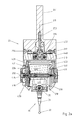
- the first embodiment of the invention shown in the FIGS. 1a to 1e is a trigger probe 20 comprising a part fixed 250, shown in detail in Figure 1b, intended to be fixed to the arm mobile of a measuring machine, by the threaded rod 251 or by another known fixing means.
- the fixed part 250 carries on its lower face 24 spheres 256, regularly arranged along a circumference and partially protruding downwards.
- the spheres 256 define 24 indexed positions and spaced 15 degrees apart for the first axis of rotation of the probe, as it is explained below. Obviously we could use a number different from spheres according to the number of indexed positions desired.
- the movable element 210 shown in Figures 1c and 1d, carries on its upper face three cylindrical pins 217.
- the flat spring 215 presses the movable member 210 against the fixed member 250.
- each of the pins 217 presses on two of the spheres 256, the six points of resulting contacts determining the relative position of elements 250 and 210 precisely and reproducibly.
- the movable element 210 can assume 24 indexed positions, spaced 15 degrees apart, around the first axis of rotation 211, which corresponds to the geometric axis of the probe.
- the same result could have been obtained by others equivalent arrangements, for example by placing the spheres on the movable element and the pins on the fixed element, or by replacing spherical or cylindrical surfaces of pins or spheres by inclined planes, or using six cylindrical pins that do not have each one point of contact with one of the spheres.
- the release mechanism 300 shown in Figures 1d and 1e allows the rotation of the movable element 210 around the axis 211.
- the transmission 300 consists of a toothed wheel 301, driven by the four racks 305, and by the helical inclined surfaces 302.
- the racks 305 rotate the toothed wheel 301 and the inclined planes 302 which are united to it, and which, sliding on their supports (not shown on the figures), axially separate the fixed element 250 from the movable element 210. In the separated position the spheres 256 protrude above the pins 217 without touching them, and rotation around the axis 211 is possible.
- the bearing force of pins 217 on spheres 256 must be high enough to prevent accidental movement of the mobile part 210 during the measurement.
- a reduction ratio of 1: 2 includes a operating force at buttons 310 of approximately 15 N, i.e. 1.5 Kgf approximately, that the user can exercise without great difficulty.
- the stroke of the buttons 310 remains contained, with this reduction ratio, at a few millimeters.
- buttons 310 While the buttons 310 are pressed in the direction radial, the operator can rotate the movable element 210 around the axis 211, by acting on the same buttons in tangential direction. This operation is very intuitive and can easily be carried out with two fingers with one hand. In this condition, the distance between the spheres 256 and the pins 217 is sufficient to avoid any contact or friction of the indexing surfaces, thus preserving positioning accuracy in indexed position. It is therefore not necessary to release the buttons 310 to switch from unlocking to rotation of the probe then to lock again the probe.
- the reduction ratio and the friction coefficients of materials used are chosen so that the transmission 300 is reversible, so that the movable element 210 spontaneously returns to position indexed, once the buttons 310 are released, thus avoiding a accidental use in free position.
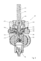
- the first mobile element 210 is connected to a second element mobile 220, able to rotate about the axis of rotation 212, perpendicular to the first axis of rotation 211, to which is fixed a mobile key 30 of known type, as can be seen in the figure 2a.
- the second mobile element 220 is pressed against the first movable element 210, in the axial direction defined by the axis of rotation 212, by the compression spring 225.
- a ring of spheres 226 is produced on a vertical face of the mobile element 220 and interacts with three cylindrical pins (not shown in the figure) placed on the face adjacent to the first movable member 210, to define a number predefined indexing position exactly reproducible, so analogous to that explained above for the rotation of the first element mobile 210.
- the release and rotation system 400 of the second element mobile 220 is shown in Figure 2b.
- the clearance is carried out by pressing the two buttons 411 and 410.
- the axial force applied to the button 410 which can slide axially around the part 470 is transmitted by the two levers 430 and 450 and the horizontal arm 440, is multiplied and applied to the spring 225 by the pin 461 and the rod 460, in order to compress it, which removes the contact force between 220 and 210.
- the dimensions of the arms of the levers 430 are chosen, 450 to obtain a reduction ratio of the operating force of 1: 2, as for the first movable element 210.
- a second spring 475, stored between button 410, part 470 pushes axially to the right in Figure 2a the second movable member 220 allowing its rotation.
- the button 410 When the button 410 is pressed the second mobile element 220 is moved to the right of Figure 2a, so that the pins and indexing spheres 226 no longer touch each other, and the second element mobile 220 can rotate around axis 212.
- the rotation is printed by the operator through the button 410 which is angularly secured to the part 470 by a pin not visible in the figures.
- Button 411 opposite button 410, has a dual function provide a finger support surface to exert a force opposite to that applied to the button 410 and to facilitate the rotation of the element 220 with two fingers.
- the button 411 is in fact angularly secured to the element 220 and is rotated therewith. The use of two forces essentially in opposition avoids transmitting forces on the support of the probe, and to move the entire probe.
- buttons 410 on the second mobile element 220 by the intermediate of the rod 460 is substantially aligned and opposite to the force exerted by the spring 225, which ensures rectilinear movements and without jamming.
- the electrical signal generated by key 30 is sent either to the user, in the form of a light signal emitted by the light diode 50 ( Figure 1a), or to the machine control software which thus determines using the measurement system data, the coordinates of the point of contact in a given repository.
- the lower part of the probe 20 has one or more protective elements 218, protruding from the probe body, the function of which is to protect the shock indexing mechanism against the workpiece measure or against the support table.
- Protective element 218 can be a bead machined directly in the metal shell 217, or else an additional element made of a material capable of absorbing shocks, for example for example rubber or elastomer.
- the second mobile element 220 can assume, in this mode of realization, 7 indexed positions spaced 15 degrees apart, for a total angle of 90 degrees. This angle, in combination with the 360 degrees of possible rotation for the first rotation element 210, allows to orient the key 30 in a number of directions uniformly distributed in half a space. It would however be possible to carry out the device of the invention with a generic number of indexed positions and any gaps between them.
- Figures 4, 5a and 5b illustrate a second embodiment of the invention, in which the release mechanism 300 of the first axis 211 is produced with four pairs of identical rods and symmetrical 320.
- each pair of rods 320 is articulated with respect to a central point 323 and external forces applied to the buttons 310 are transmitted to said central points 323, when the two ends of the two links of a pair press one on the fixed element 250, and the other on the first movable element 210.
- the reduction ratio between the force axial exerted on the movable element 210 and the radial operating force applied to the buttons 310 is proportional to the tangent of the half angle opening between the rods 320. This results in a reduction ratio increasing with the spacing between the elements 250 and 210 and the angle between the rods 320. This variability in the reduction ratio is advantageous because the force required to keep the buttons pressed at the end of the stroke is minimal, which facilitates the fine orientation operation of the key 30.
- buttons 310 When the buttons 310 are fully pressed, the gap between the spheres 226 and the pins to them juxtaposed is maintained, and the spheres and pins can never come into contact between them or with other elements of the probe mechanism. In this condition the wear of the indexing surfaces is minimized essential, and the indexing precision is maintained over time.
- the force resulting on the first movable element 210 via the rods 320 is substantially axial with respect to the axis of rotation 211, either substantially aligned and opposite to the force exerted by the spring 215, which ensures rectilinear movements and without jamming.
- the operator pushes asymmetrically on only one of the buttons 310 the horizontal component of the resulting force produces friction high between the rod 253 and the sleeve 219 preventing the release of the first movable element 210. This advantageous characteristic allows to avoid inadvertent and involuntary manipulations.
- buttons 310 are surrounded by a protective membrane annular rubber or elastomer 330, which has the function of protect the internal mechanism from dirt and dust, but also prevent heat transmission from the operator's hands to internal indexing mechanism, which would have harmful consequences for indexing accuracy.
- the buttons 410 and 411, serving upon rotation and release of the second axis 212, are also made of preferably a synthetic material with good properties thermal insulation.
- a window 30 is provided on the support element 250 for reading the angle of rotation relative to the first axis 211 on a scale engraved or printed on the first movable element 210, as is can appreciate it in Figures 5a and 5b.
- the angle of rotation relative to the second axis 212 can be read on the two windows 40 cut out from the outer crown of the button 411 and visible in Figures 5a and 5c. Two windows are required in this case to allow optimal visibility in all possible orientations of the probe.
- the trigger button 30 reacts to the slightest contact with the surface of the part to be measured by generating an electrical pulse.
- the pulse is transmitted, via a processing circuit electronics not shown, at connector 70, for connection with the control device of the measuring machine, and the indicator light 50.
- the indicator lamp comprises in this embodiment a light diode, but could include other light emitters as an alternative known, such as, for example, electroluminescent elements in sheet form or in wire.
- the light diode is surmounted by an optical diffuser of light, allowing to see the light emitted in a large range angles of observation.
- the indicator 50 is replaced by several indicator lights, placed in different places of the feeler, so that at least one indicator is visible from each angle possible observation.
- the indicator 50 includes one or more light conductors for emitting light produced by one or more light sources from different areas of the probe surface, so that the light indication is visible from every possible viewing angle.
- the device of the invention could also be produced without having use of an indexing mechanism, but with simple mechanisms to friction allowing the axes to be blocked in an infinite number of orientations.
- the invention also includes an embodiment in which the rotation and disengagement of the axes are actuated by actuators automatic, for example electric motors and / or solenoids.
- the rotation of the axes of the probe is ensured by servomotors comprising encoders for measuring the angles of orientation of the button.
- servomotors comprising encoders for measuring the angles of orientation of the button.
- the indexing mechanism described above can be preserved, or deleted if the positioning accuracy of the servomotors is sufficient for envisaged applications.
Landscapes
- Physics & Mathematics (AREA)
- General Physics & Mathematics (AREA)
- A Measuring Device Byusing Mechanical Method (AREA)
- Length Measuring Devices With Unspecified Measuring Means (AREA)
- Machine Tool Sensing Apparatuses (AREA)
Priority Applications (5)
| Application Number | Priority Date | Filing Date | Title |
|---|---|---|---|
| EP03100524A EP1443300B1 (de) | 2003-01-29 | 2003-03-03 | Lenkbarer Taststift |
| CNB2003101195422A CN100374813C (zh) | 2003-01-29 | 2003-11-28 | 可调整的探头 |
| US10/760,781 US6907673B2 (en) | 2003-01-29 | 2004-01-20 | Adjustable probe |
| JP2004020003A JP3954579B2 (ja) | 2003-01-29 | 2004-01-28 | 可変方向トリガプローブ |
| HK04109162.9A HK1066270B (en) | 2003-01-29 | 2004-11-19 | Adjustable probe |
Applications Claiming Priority (3)
| Application Number | Priority Date | Filing Date | Title |
|---|---|---|---|
| EP03001836 | 2003-01-29 | ||
| EP03001836A EP1443299B1 (de) | 2003-01-29 | 2003-01-29 | Taststift mit einstellbarer Orientierung |
| EP03100524A EP1443300B1 (de) | 2003-01-29 | 2003-03-03 | Lenkbarer Taststift |
Publications (3)
| Publication Number | Publication Date |
|---|---|
| EP1443300A2 true EP1443300A2 (de) | 2004-08-04 |
| EP1443300A3 EP1443300A3 (de) | 2005-02-02 |
| EP1443300B1 EP1443300B1 (de) | 2010-02-24 |
Family
ID=32658190
Family Applications (1)
| Application Number | Title | Priority Date | Filing Date |
|---|---|---|---|
| EP03100524A Expired - Lifetime EP1443300B1 (de) | 2003-01-29 | 2003-03-03 | Lenkbarer Taststift |
Country Status (4)
| Country | Link |
|---|---|
| US (1) | US6907673B2 (de) |
| EP (1) | EP1443300B1 (de) |
| JP (1) | JP3954579B2 (de) |
| CN (1) | CN100374813C (de) |
Families Citing this family (13)
| Publication number | Priority date | Publication date | Assignee | Title |
|---|---|---|---|---|
| EP1443301B1 (de) * | 2003-01-29 | 2010-02-10 | Tesa SA | Lenkbarer Taststift |
| GB0322115D0 (en) | 2003-09-22 | 2003-10-22 | Renishaw Plc | Method of error compensation |
| EP1617171B1 (de) * | 2004-07-12 | 2007-12-12 | Tesa S.A. | Taster zur Messung in drei Dimensionen |
| EP2028439A1 (de) * | 2007-07-26 | 2009-02-25 | Renishaw plc | Abschaltbares Messgerät |
| TWI468696B (zh) * | 2009-08-12 | 2015-01-11 | Hon Hai Prec Ind Co Ltd | 微調裝置 |
| TWI458938B (zh) | 2011-01-19 | 2014-11-01 | Renishaw Plc | 用於機械工具裝置之類比量測探針 |
| WO2013007285A1 (de) * | 2011-07-08 | 2013-01-17 | Carl Zeiss Industrielle Messtechnik Gmbh | Korrektur und/oder vermeidung von fehlern bei der messung von koordinaten eines werkstücks |
| EP2629048B1 (de) * | 2012-02-20 | 2018-10-24 | Tesa Sa | Messtaster |
| ES2784149T3 (es) | 2012-03-22 | 2020-09-22 | Balance Systems Srl | Dispositivo de medida que incluye galga para piezas de trabajo |
| DE102016226087B4 (de) * | 2016-12-22 | 2023-02-16 | Carl Zeiss Industrielle Messtechnik Gmbh | Dreh-Schwenk-Sensorsystem für ein Koordinatenmessgerät |
| CN106926058A (zh) * | 2017-03-24 | 2017-07-07 | 苏州麦凯斯威传感技术有限公司 | 三分量接触式传感器 |
| WO2022175656A1 (en) | 2021-02-17 | 2022-08-25 | Renishaw Plc | Articulated head |
| CN117109486B (zh) * | 2023-10-23 | 2024-01-23 | 北京华力兴科技发展有限责任公司 | 一种x射线测厚仪探头 |
Family Cites Families (20)
| Publication number | Priority date | Publication date | Assignee | Title |
|---|---|---|---|---|
| GB1593050A (en) * | 1976-09-30 | 1981-07-15 | Renishaw Electrical Ltd | Contact sensing probe |
| IT1088539B (it) * | 1976-12-24 | 1985-06-10 | Rolls Royce | Sonda per l'uso in apparecchi di misura |
| GB1597842A (en) * | 1977-02-07 | 1981-09-09 | Rolls Royce | Indexing mechanism |
| DE2712181C3 (de) * | 1977-03-19 | 1981-01-22 | Fa. Carl Zeiss, 7920 Heidenheim | Tastsystem |
| US4510693A (en) * | 1982-06-14 | 1985-04-16 | Gte Valeron Corporation | Probe with stylus adjustment |
| CH672370A5 (de) * | 1987-09-15 | 1989-11-15 | Tesa Sa | |
| DE3740070A1 (de) * | 1987-11-26 | 1989-06-08 | Zeiss Carl Fa | Dreh-schwenk-einrichtung fuer tastkoepfe von koordinatenmessgeraeten |
| US4979284A (en) * | 1987-12-05 | 1990-12-25 | Renishaw Plc | Apparatus for changing a sensing device |
| DE69003149T2 (de) * | 1989-04-14 | 1994-01-05 | Renishaw Plc | Tastkopf. |
| EP0392699B1 (de) * | 1989-04-14 | 1993-09-22 | Renishaw plc | Tastkopf |
| US5209131A (en) * | 1989-11-03 | 1993-05-11 | Rank Taylor Hobson | Metrology |
| US5339535A (en) * | 1990-02-23 | 1994-08-23 | Renishaw Metrology Limited | Touch probe |
| JPH08509299A (ja) * | 1994-02-18 | 1996-10-01 | レニショウ パブリック リミテッド カンパニー | 測定プローブ |
| CN2221772Y (zh) * | 1994-12-23 | 1996-03-06 | 蓝绿江 | 三维测头 |
| DE19501178C2 (de) * | 1995-01-17 | 1996-05-02 | Klingelnberg Soehne | Schwenkbarer Zwei-Koordinaten-Tastkopf mit horizontaler Hauptachse |
| DE69617148T3 (de) * | 1995-09-25 | 2005-11-10 | Mitutoyo Corp., Kawasaki | Fühlerprobe |
| DE19703690A1 (de) * | 1996-04-15 | 1997-10-16 | Zeiss Carl Fa | Meßeinrichtung zur Vermessung von Werkstücken |
| CN2300088Y (zh) * | 1997-04-17 | 1998-12-09 | 中国人民解放军国防科学技术大学 | 活塞外轮廓测量仪 |
| DE10006753A1 (de) * | 2000-02-15 | 2001-08-16 | Zeiss Carl | Dreh-Schwenkeinrichtung für den Tastkopf eines Koordinatenmeßgerätes |
| EP1443301B1 (de) * | 2003-01-29 | 2010-02-10 | Tesa SA | Lenkbarer Taststift |
-
2003
- 2003-03-03 EP EP03100524A patent/EP1443300B1/de not_active Expired - Lifetime
- 2003-11-28 CN CNB2003101195422A patent/CN100374813C/zh not_active Expired - Lifetime
-
2004
- 2004-01-20 US US10/760,781 patent/US6907673B2/en not_active Expired - Lifetime
- 2004-01-28 JP JP2004020003A patent/JP3954579B2/ja not_active Expired - Fee Related
Also Published As
| Publication number | Publication date |
|---|---|
| HK1066270A1 (zh) | 2005-03-18 |
| JP3954579B2 (ja) | 2007-08-08 |
| EP1443300A3 (de) | 2005-02-02 |
| CN100374813C (zh) | 2008-03-12 |
| CN1517668A (zh) | 2004-08-04 |
| EP1443300B1 (de) | 2010-02-24 |
| JP2004233359A (ja) | 2004-08-19 |
| US20040148792A1 (en) | 2004-08-05 |
| US6907673B2 (en) | 2005-06-21 |
Similar Documents
| Publication | Publication Date | Title |
|---|---|---|
| EP1443301B1 (de) | Lenkbarer Taststift | |
| EP1443299B1 (de) | Taststift mit einstellbarer Orientierung | |
| EP1443302B1 (de) | Lenkbarer Taststift | |
| EP1443300B1 (de) | Lenkbarer Taststift | |
| EP1617171B1 (de) | Taster zur Messung in drei Dimensionen | |
| EP1666833B1 (de) | Motorisierter und orientierbarer Messkopf | |
| CA3105716C (fr) | Bras de mesure avec extremite multifonction | |
| CA3105634C (fr) | Bras de mesure avec extremite multifonction | |
| CA3105643C (fr) | Bras de mesure avec extremite multifonction | |
| CA3105644C (fr) | Bras de mesure avec extremite multifonction | |
| CA3105639C (fr) | Bras de mesure avec extremite multifonction | |
| EP1666832B1 (de) | Motorisierter orientierbarer Messkopf | |
| EP1617172B1 (de) | Lenkbarer Taststift | |
| EP1672309B1 (de) | Motorisierter und orientierbarer Messkopf | |
| EP1646934A1 (de) | Eingabeeinheit für computer oder dergleichen | |
| EP1977304A1 (de) | Verbesserungen an eingabeperipheriegeräten für computer oder dergleichen | |
| FR2912232A1 (fr) | Souris optique 3d suspendu | |
| HK1066269B (en) | Adjustable probe |
Legal Events
| Date | Code | Title | Description |
|---|---|---|---|
| PUAI | Public reference made under article 153(3) epc to a published international application that has entered the european phase |
Free format text: ORIGINAL CODE: 0009012 |
|
| AK | Designated contracting states |
Kind code of ref document: A2 Designated state(s): AT BE BG CH CY CZ DE DK EE ES FI FR GB GR HU IE IT LI LU MC NL PT RO SE SI SK TR |
|
| AX | Request for extension of the european patent |
Extension state: AL LT LV MK |
|
| PUAL | Search report despatched |
Free format text: ORIGINAL CODE: 0009013 |
|
| AK | Designated contracting states |
Kind code of ref document: A3 Designated state(s): AT BE BG CH CY CZ DE DK EE ES FI FR GB GR HU IE IT LI LU MC NL PT RO SE SI SK TR |
|
| AX | Request for extension of the european patent |
Extension state: AL LT LV MK |
|
| RIC1 | Information provided on ipc code assigned before grant |
Ipc: 7G 01B 11/00 B Ipc: 7G 01B 7/012 B Ipc: 7G 01B 5/012 A Ipc: 7G 01B 21/04 B |
|
| 17P | Request for examination filed |
Effective date: 20050711 |
|
| RBV | Designated contracting states (corrected) |
Designated state(s): AT BE BG CH CY CZ DE DK EE ES FI FR GB GR HU IE IT LI LU MC NL PT RO SE SI SK TR |
|
| AKX | Designation fees paid |
Designated state(s): CH DE FR GB LI |
|
| 17Q | First examination report despatched |
Effective date: 20070808 |
|
| GRAP | Despatch of communication of intention to grant a patent |
Free format text: ORIGINAL CODE: EPIDOSNIGR1 |
|
| GRAS | Grant fee paid |
Free format text: ORIGINAL CODE: EPIDOSNIGR3 |
|
| GRAA | (expected) grant |
Free format text: ORIGINAL CODE: 0009210 |
|
| AK | Designated contracting states |
Kind code of ref document: B1 Designated state(s): CH DE FR GB LI |
|
| REG | Reference to a national code |
Ref country code: GB Ref legal event code: FG4D Free format text: NOT ENGLISH |
|
| REG | Reference to a national code |
Ref country code: CH Ref legal event code: EP |
|
| REG | Reference to a national code |
Ref country code: CH Ref legal event code: NV Representative=s name: PATENTS & TECHNOLOGY SURVEYS SA |
|
| REF | Corresponds to: |
Ref document number: 60331408 Country of ref document: DE Date of ref document: 20100408 Kind code of ref document: P |
|
| PLBE | No opposition filed within time limit |
Free format text: ORIGINAL CODE: 0009261 |
|
| STAA | Information on the status of an ep patent application or granted ep patent |
Free format text: STATUS: NO OPPOSITION FILED WITHIN TIME LIMIT |
|
| 26N | No opposition filed |
Effective date: 20101125 |
|
| REG | Reference to a national code |
Ref country code: CH Ref legal event code: PFA Owner name: TESA SA Free format text: TESA SA#BUGNON 38#1020 RENENS (CH) -TRANSFER TO- TESA SA#BUGNON 38#1020 RENENS (CH) |
|
| PGFP | Annual fee paid to national office [announced via postgrant information from national office to epo] |
Ref country code: CH Payment date: 20140319 Year of fee payment: 12 |
|
| PGFP | Annual fee paid to national office [announced via postgrant information from national office to epo] |
Ref country code: FR Payment date: 20140319 Year of fee payment: 12 |
|
| REG | Reference to a national code |
Ref country code: CH Ref legal event code: PL |
|
| REG | Reference to a national code |
Ref country code: FR Ref legal event code: ST Effective date: 20151130 |
|
| PG25 | Lapsed in a contracting state [announced via postgrant information from national office to epo] |
Ref country code: LI Free format text: LAPSE BECAUSE OF NON-PAYMENT OF DUE FEES Effective date: 20150331 Ref country code: CH Free format text: LAPSE BECAUSE OF NON-PAYMENT OF DUE FEES Effective date: 20150331 |
|
| PG25 | Lapsed in a contracting state [announced via postgrant information from national office to epo] |
Ref country code: FR Free format text: LAPSE BECAUSE OF NON-PAYMENT OF DUE FEES Effective date: 20150331 |
|
| REG | Reference to a national code |
Ref country code: DE Ref legal event code: R084 Ref document number: 60331408 Country of ref document: DE |
|
| PGFP | Annual fee paid to national office [announced via postgrant information from national office to epo] |
Ref country code: GB Payment date: 20170322 Year of fee payment: 15 |
|
| GBPC | Gb: european patent ceased through non-payment of renewal fee |
Effective date: 20180303 |
|
| PG25 | Lapsed in a contracting state [announced via postgrant information from national office to epo] |
Ref country code: GB Free format text: LAPSE BECAUSE OF NON-PAYMENT OF DUE FEES Effective date: 20180303 |
|
| REG | Reference to a national code |
Ref country code: DE Ref legal event code: R082 Ref document number: 60331408 Country of ref document: DE Representative=s name: BECK & ROESSIG - EUROPEAN PATENT ATTORNEYS, DE |
|
| PGFP | Annual fee paid to national office [announced via postgrant information from national office to epo] |
Ref country code: DE Payment date: 20220322 Year of fee payment: 20 |
|
| REG | Reference to a national code |
Ref country code: DE Ref legal event code: R071 Ref document number: 60331408 Country of ref document: DE |