EP1443431A1 - Bauproduktionsinformationsintegrationssystem - Google Patents
Bauproduktionsinformationsintegrationssystem Download PDFInfo
- Publication number
- EP1443431A1 EP1443431A1 EP02802715A EP02802715A EP1443431A1 EP 1443431 A1 EP1443431 A1 EP 1443431A1 EP 02802715 A EP02802715 A EP 02802715A EP 02802715 A EP02802715 A EP 02802715A EP 1443431 A1 EP1443431 A1 EP 1443431A1
- Authority
- EP
- European Patent Office
- Prior art keywords
- cad
- information
- building
- equipment
- data
- Prior art date
- Legal status (The legal status is an assumption and is not a legal conclusion. Google has not performed a legal analysis and makes no representation as to the accuracy of the status listed.)
- Withdrawn
Links
Images




Classifications
-
- G—PHYSICS
- G06—COMPUTING OR CALCULATING; COUNTING
- G06F—ELECTRIC DIGITAL DATA PROCESSING
- G06F30/00—Computer-aided design [CAD]
- G06F30/10—Geometric CAD
- G06F30/13—Architectural design, e.g. computer-aided architectural design [CAAD] related to design of buildings, bridges, landscapes, production plants or roads
-
- Y—GENERAL TAGGING OF NEW TECHNOLOGICAL DEVELOPMENTS; GENERAL TAGGING OF CROSS-SECTIONAL TECHNOLOGIES SPANNING OVER SEVERAL SECTIONS OF THE IPC; TECHNICAL SUBJECTS COVERED BY FORMER USPC CROSS-REFERENCE ART COLLECTIONS [XRACs] AND DIGESTS
- Y10—TECHNICAL SUBJECTS COVERED BY FORMER USPC
- Y10S—TECHNICAL SUBJECTS COVERED BY FORMER USPC CROSS-REFERENCE ART COLLECTIONS [XRACs] AND DIGESTS
- Y10S707/00—Data processing: database and file management or data structures
- Y10S707/99951—File or database maintenance
- Y10S707/99952—Coherency, e.g. same view to multiple users
- Y10S707/99953—Recoverability
-
- Y—GENERAL TAGGING OF NEW TECHNOLOGICAL DEVELOPMENTS; GENERAL TAGGING OF CROSS-SECTIONAL TECHNOLOGIES SPANNING OVER SEVERAL SECTIONS OF THE IPC; TECHNICAL SUBJECTS COVERED BY FORMER USPC CROSS-REFERENCE ART COLLECTIONS [XRACs] AND DIGESTS
- Y10—TECHNICAL SUBJECTS COVERED BY FORMER USPC
- Y10S—TECHNICAL SUBJECTS COVERED BY FORMER USPC CROSS-REFERENCE ART COLLECTIONS [XRACs] AND DIGESTS
- Y10S707/00—Data processing: database and file management or data structures
- Y10S707/99951—File or database maintenance
- Y10S707/99956—File allocation
-
- Y—GENERAL TAGGING OF NEW TECHNOLOGICAL DEVELOPMENTS; GENERAL TAGGING OF CROSS-SECTIONAL TECHNOLOGIES SPANNING OVER SEVERAL SECTIONS OF THE IPC; TECHNICAL SUBJECTS COVERED BY FORMER USPC CROSS-REFERENCE ART COLLECTIONS [XRACs] AND DIGESTS
- Y10—TECHNICAL SUBJECTS COVERED BY FORMER USPC
- Y10S—TECHNICAL SUBJECTS COVERED BY FORMER USPC CROSS-REFERENCE ART COLLECTIONS [XRACs] AND DIGESTS
- Y10S715/00—Data processing: presentation processing of document, operator interface processing, and screen saver display processing
- Y10S715/961—Operator interface with visual structure or function dictated by intended use
- Y10S715/964—CAD or CAM, e.g. interactive design tools
Definitions
- the present invention relates to an integrated building production information system capable of making the work solution of a design department and an execution department more rational and more efficient by electronicizing key jobs (integration, estimation, procurement, profit-and-loss management and the like) of the production side in a field of construction.
- the present invention relates to a database CAD (computer-aided design) system which can aim at making more efficient and more laborsaving the work of preparing design drawings and specifications and at improving the productivity and quality by making it possible for personal computers using CAD software connected with a database to grasp necessary quantities and share necessary data for design among the personal computers, by integrating specifications and quantities in a design work using CAD's performed by each personal computer, and by unifying the data flow from design information to estimation and execution information.
- CAD computer-aided design
- execution design drawings and specifications representing the contents of estimation and contract have contained a too small amount of information and a too large amount of pending contents to perform execution as they are.
- drawings of the building side such as plan detail drawings, skeleton drawings and the like to be prepared by building CAD apparatuses are made by the respective building CAD apparatuses.
- the prepared drawings have the data formats of the respective dedicated CAD apparatuses, they are converted into the DXF format and converted from each unique layer of these dedicated CAD apparatuses into the layer of the synthetic CAD apparatus.
- the prepared drawings have the data formats of the respective dedicated CAD apparatuses, they are converted into the DXF format and converted from each unique layer of these dedicated CAD apparatuses into the layer of the synthetic CAD apparatus.
- a processing synthetic CAD apparatus in a synthetic CAD apparatus can handle uniformly drawings made by a building CAD apparatus or an equipment CAD apparatus.
- a synthetic CAD apparatus converts the data format and layer of a changed drawing and passes the converted drawing data to another building CAD apparatus or equipment CAD apparatus, which can perform a necessary change on the basis of the changed drawing data by means of each dedicated CAD.
- the changed drawing is converted in the synthetic CAD apparatus side and is combined with a layer according to a synthetic drawing and outputted to a display device or a plotter.
- said synthetic drawing preparation system of Japanese Patent Laid-Open Publication No. Hei 8-235,243 is a system for securing the compatibility in a job of making a synthetic drawing at an execution stage but is not a system for securing the compatibility at a design stage. Securing the compatibility at an execution stage results in having many pending matters, and redo and readjustment occur even in the course of execution as described above and the rationalization is hindered in various aspects by entering the next process as leaving necessary information not definitely determined.
- pattern data of a drawing but does not inheritably use the attribute of a design drawing.
- the linkage of such pattern data is low in the degree of freedom and the CAD data of a design drawing can be utilized in making a synthetic drawing in the next process as pattern data, but since the attribute of it is not utilized, the data cannot be utilized in calculation of quantities to be estimated.
- said synthetic drawing preparation system of Japanese Patent Laid-Open Publication No. Hei 8-235,243 is a system which fully performs a layer management of drawing data and converts the layer of drawing data into a layer configuration convenient for a synthetic drawing on the basis of a predetermined rule of layer conversion, but the layer rule is not often strictly observed and an effective result cannot be often obtained.
- management based on layer is effective for an object but is often ineffective for another object, and in case of using a layer management for another object, such a system performs conversion but often cannot effectively distribute data.
- the synthetic drawing preparation system of Japanese Patent Laid-Open Publication No. Hei 8-235,243 is supposed as a system primarily handling two-dimensional matters and cannot perform examination from an optional direction in confirming the compatibility and is difficult to estimate exactly the quantities.
- the work of a conventional CAD system is only the exchange of pattern data in the DWG format or DXF format and exchanges data having no attribute from beginning to end.
- the present invention aims at solving said disadvantages of the prior art, and a first object of the invention is to realize improving the quality of a design drawing and provide an integrated building production information system in which information is unified by developing a function of linking CAD information and high-quality data being excellent in compatibility made at an execution design stage can be obtained as a result that the compatibility can be spontaneously obtained or that the efficiency of collation work can be improved.
- a second object of the invention is to shorten the whole process and provide an integrated building production information system in which a work of making data compatible can be easily advanced further in a short time, and, therefore, the whole process is shortened and furthermore, the compatible data can be diverted and utilized at the estimation and execution stages after the execution design stage and the efficiency of building production can be comprehensively improved.
- a first feature of the present invention in order to achieve the above-mentioned objects provides as its main purport an integrated building production information system comprising a design CAD based on software of building, structure and equipment, and a database built in the outside separately from this design CAD, said database making an integrated DB-CAD system of building, structure and equipment as an execution-linked system in DB-CAD's sharing data of a standard database, wherein said integrated building production information system stores the information made compatible by three-dimensional superposition at the time of design into the shared database (DB) of the integrated DB-CAD system and further receives and links information of this shared database to external systems such as a skeleton drawing CAD, reinforcing bar and steel frame systems and the like and makes execution information.
- DB shared database
- design CAD's are based on different software products according to the respective features of building, structure and equipment (building: Graphisoft, structure: AutoCAD, and equipment: CADWe'll CAPE) and databases share MDB data of Microsoft Access being a standard database of Kajima, and since a database made of CAD data is not shared but a database disconnected separately from CAD is made in the outside and shared in such a way, it is enough to develop only an interface part for connecting a CAD software product with a database and exchanging information between them.
- an execution-linked system for estimating quantities and making execution drawings
- DB-CAD database CAD
- receives information of a shared database diverts design data to the execution-linked system and thereby links these data to a skeleton drawing CAD or reinforcing bar and steel frame systems, and performs consistently operations to the estimation of quantities and the preparation of execution drawings, and thereby makes it possible to improve the efficiency of work and reduce the expense of estimation/preparation of execution drawings.
- information of the shared database is excellent in compatibility due to integrated utilization of DB-CAD's of building, structure and equipment systems, and can be made higher in degree of definite settlement by making execution design drawings, and makes it possible to take information of an execution side into design at an early stage and improve the compatibility and linkage between design drawings and execution drawings.
- a branch office or the like can manage for itself the quantities to be the core of a building by utilizing the estimated quantities; and by incorporating information of the execution side into design at an early stage and performing a high-compatibility design being high in degree of definite settlement, it is possible to reduce redoing jobs caused by design and site works spent for improving the degree of definite settlement of design.
- a skeleton drawing can also be automatically made on the basis of said synthetic drawing, the reliability of it is high.
- data is utilized as an equipment execution original drawing, which is diverted to an equipment execution drawing by a cooperative company and can be utilized in a job in which execution has been started.
- the sorting by attribute is effective without depending on layer.
- the contents described in a DB are linked to a CAD of an execution system
- since the linked contents are reproduced by a CAD software function at the linked side there is the merit that work can be performed in a layer configuration convenient for the linked side regardless of the layer configuration at the original CAD software side.
- the original CAD software side can also do with a layer configuration convenient to itself and does not need to consider the layer configuration of the linked side.
- the linkage through DB has a merit that it can be performed regardless of layer configuration.
- the system performs superposition of plans by a two-dimensional CAD software product, superposition of plan sections and elevation sections at predetermined positions by a three-dimensional CAD software product and further new superposition of three-dimensional objects by a three-dimensional CAD software product, said superposition having been used up to now as means for securing the compatibility; and the three-dimensional superposition has the following merits.
- the present invention makes it possible to immediately find incompatibility by viewing a part to be verified from an optional direction out of 360°.
- a conventional superposition method of plan sections and elevation sections cut out by a three-dimensional CAD has specified in advance the positions of sections to be superposed, cut out these sections by CAD's of the respective systems and then checked the superposed part.
- the present invention provides and reproduces three-dimensional information as data of DB or data in the IFC format from building and equipment DB's to a three-dimensional building CAD.
- a second feature of the present invention provides as its purport an integrated building production information system, wherein a design CAD makes a building model virtually reproducing a building to be actually built after now inside a computer software product using a personal computer-based three-dimensional CAD programmed so that a shape made on CAD software and an attribute being its own property are linked with each other on the CAD software, and stores building specifications such as the specifications, dimensions, quantities, heights and the like of a structural skeleton, finish, fittings, equipment piping, ducts, and machines and instruments as attribute data into the shared database.
- a design CAD makes a virtual building model (virtually reproducing a building to be actually built from now in a piece of computer software) by means of a personal computer-based three-dimensional CAD having an obj ect function (programmed so that an object drawn on a piece of CAD software behaves having an attribute being its own property within the CAD software) and has such attributes as the specifications, dimensions, quantities, heights (position information) and the like of a structural skeleton, finish, fittings, equipment piping, ducts, and machines and instruments stored in a shared database, by reading and reproducing the information by means of the CAD software of the execution side it is possible to reproduce attribute information as well as pattern information, save a labor of repetitive input, and continue working in a layer configuration convenient to its own CAD software.
- the linkage of a shape made on such object-oriented CAD software to its attribute in the CAD software means that when the shape is changed the quantity is also changed at the same time.
- a building has a wall and in case of providing a window in this building, the window has the property of making a hole in the wall.
- the linkage is a sequence of changes that when the window is changed in size the hole is also changed in size (the wall is also changed in area).
- the linkage In case of equipment, for example, in case of piping, the linkage has use, piping material and size as attribute, and in case of branching, it generates a joint having a shape adapted to its material and size and makes it impossible to join pipes having different uses with each other.
- two-dimensional plane data are superposed and the incompatibility in height has been judged by a person.
- a contrivance for making it easy to find the incompatibility in height by performing a layer classification by height information, giving symbols to and classifying in advance layers such as a ceiling surface, ceiling inside, wall surface, floor surface and the like, and performing a layer change on the superposed drawings.
- the present invention makes it possible to confirm the compatibility from an optional direction in a short time by newly superposing three-dimensional objects as they are as a means for storing compatible information.
- a system of the invention makes it possible to reproduce attribute information as well as pattern information, save a labor of repetitive input and continue working in a layer configuration convenient to its own CAD software by reading and reproducing information stored in a shared database by means of a CAD software product of the execution side.
- a third feature of the present invention provides an integrated building production information system having the following matters as its purport.
- Design CAD's are built in the outside separately from design CAD's and these design CAD's are based on building, structure and equipment software products.
- the databases make it possible to grasp and share the quantities by sorting data of a standard database into character information and pattern information by means of a design CAD on a personal computer, unify specifications and quantities and unify data flows from design information to estimation and execution information.
- the invention makes an integrated DB-CAD database of building, structure and equipment as an execution-linked system in DB-CAD's, and links and integrates with one another the database CAD's comprising three DB-CAD's including a building DB-CAD related to finish, fittings and the like, an equipment DB-CAD related to machines and instruments, piping, ducts, wiring and the like, and a structure DB-CAD related to columns, beams, slabs and the like.
- a means for linking and integrating these DB-CAD's with one another provides equipment 3-D information (three-dimensional information of equipment) from the equipment DB-CAD to the building DB-CAD, returns 3-D interference information from the building DB-CAD to the equipment DB-CAD, and provides plan information (plan drawing, room area, room name, ceiling height and floor height) and skeleton information such as building shape information, building member information, building section information and the like at the beginning of making drawings, between the structure DB-CAD and the equipment DB-CAD, said means provides such skeleton information as building shape information, building member information, building section information and the like from the structure DB-CAD to the equipment DB-CAD, and returns skeleton opening (sleeve) information such as information of making a hole in said skeleton information from the equipment DB-CAD to the structure DB-CAD, and between the building DB-CAD and the structure DB-CAD, said means transfers reciprocally such skeleton information as building shape information,
- a fourth feature of the present invention provides as its purport an integrated building production information system for realizing the linkage of data between different CAD software products, further transferring reciprocally data described with character information (DB information), realizing the exchange of three-dimensional data with attribute, and making the information reading CAD side reproduce the attribute and pattern on the basis of this information.
- DB information character information
- the present invention intending to realize the data linkage between different CAD software products, makes it possible to take in information and secure the compatibility by means of a method which performs the guarantee of compatibility and the unification of data, makes a means of three-dimensional superposition, and, therefore, reciprocally transfers data described with character information (DB information) and realizes the exchange of three-dimensional data with attribute and makes the data reading CAD side reproduce the attribute and pattern on the basis of the information.
- DB information character information
- the linkage of the building DB-CAD with the structure DB-CAD make it possible to secure the compatibility of skeleton;
- the linkage of the building DB-CAD with the equipment DB-CAD makes it possible to confirm and secure the compatibility of the contents of equipment with a building plan, and reproduce a building plan at the start of drawing figures;
- the linkage of the structure DB-CAD with the equipment DB-CAD makes it possible to reproduce the skeleton at the beginning of drawing figures and return the skeleton opening information to the structure DB-CAD.
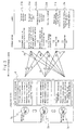
- Figure 1 is an explanatory diagram showing an embodiment of an integrated building production information system of the present invention, and numbers 1, 2 and 3 in this figure are respectively a building CAD, a structure CAD and an equipment CAD as design CAD's, and are based on different software products according to their respective features.
- databases DB-CAD (building) 1a, DB-CAD (structure) 2a and DB-CAD (equipment) 3a built in the outside separately from these design CAD's including building CAD 1, structure CAD 2 and equipment CAD 3.
- the exchange of data between a CAD and an external DB is ordinarily performed as text data obtained by being converted into the CSV (comma separated value) format, and an interface making it possible to directly write/read from building CAD 1 to a specific DB-CAD (building) 1a utilizing the Access Link function of specific software is used.
- the design model can be utilized as a skeleton drawing preparation model, but the effect of attributes possessed by an object in this DB-CAD (building) 1a is in that building elements such as columns, beams, openings and the like are collected and various attributes such as areas, specifications and the like are stored in a specific DB due to a fact that building CAD 1 is linked with the specific DB. Therefore, when a model corresponding to each stage of design has been made, at the same time it is possible to grasp a floor area, finished areas of a wall, ceiling and the like, and the quantity of parts and further rough estimation and the like. A designer can advance a rational design meeting the requirements of a customer as considering these data. On the other hand, an estimation department can effectively utilize these numerical data. It is possible not only to directly input these data into an estimation system but also to utilize them in checking data from an estimation office.
- DB-CAD structure 2a
- structure CAD 2a when a drawing is made by structure CAD 2, its drawing information is automatically stored as character data into a DB through a building model, and contrarily when data of the DB is changed, the change is automatically reflected in an associated drawing.
- General information of a building information about materials and member section information out of structural design information of input data contents into DB-CAD (structure) 2a are stored as an ACCESS file at the time of input.
- information about the shape of a building and the arrangement of members is kept as a three-dimensional model of CAD at the time of an input operation.
- a database in which information about the shape of a building and information about the arrangement of members are stored as a three-dimensional model of CAD at the time of input and structure CAD 2 which outputs the information stored as said three-dimensional model of CAD to a file of said specific format through batch processing at the time of linking with an external system are provided and the whole structure design information is standardized into a fixed form.
- a structure design department can unify structure design information and pursue the improvement in efficiency of design work by utilizing a skeleton database CAD having files of a specific format of this system being a three-dimensional CAD. And at a design stage, the result of planning is automatically inputted into a skeleton database and thereby, original data for a structure computation can be generated. Since the compatibility between various drawings of structural design and structural computation can automatically be obtained through a three-dimensional model of CAD and a skeleton database, the efficiency of design work can be improved.
- output drawings there are a framing plan, framing elevation (automatically made) and a detailed reinforcing bar drawing (automatically made), and additionally, there are a detailed steel frame drawing (automatically made), a section list (semi-automatically made) and a skeleton DB output, and further there is also prepared a layout function for making various mixed drawings.
- DB-CAD (equipment) 3a is composed of equipment CAD 3 for preparing equipment drawings and a DB combined with each other, inputs and stores specifications of machines and instruments by means of equipment CAD 3, associates drawing information of a design drawing with machine and instrument information of a specific DB, outputs one or plural pieces of arrangement information of machines and instruments, quantity information of materials and equipment opening information from a design drawing into its own DB, and takes out one or plural pieces of data for drawings, specifications, estimation and execution.
- the system passes the information of specifications, arrangement and quantities of machines and instruments and the quantity information of materials as character-based information to an adjustment and estimation system, and diverts a design drawing as pattern (drawing) information to an execution drawing or a completed building drawing.
- DB-CAD (equipment) 3a has a job registering function, a machine and instrument specifications registering and editing function and a various output data preparing function
- equipment CAD 3 has a function of referring machine and instrument specifications information registered at its own DB, a function of linking machines and instruments registered at its own DB with symbols, a function of outputting arrangement information of machines and instruments to its own DB, a function of outputting equipment opening information into its own DB, a function of outputting the quantities of materials, and a function of adding attributes necessary for outputting the quantities.
- An integrated DB-CAD obtained by integrating these means stores compatible information into the shared database 4, and further an execution system 5 available on the market receives information of this shared database 4, links the received information to a skeleton drawing CAD or a reinforcing bar and steel frame system on the market for a bill of quantities 6, a synthetic drawing and skeleton drawing 7, a reinforcement quantity execution drawing 8, a steel frame quantity execution drawing 9 and the like.
- the shared database 4 has three CAD's including building CAD 1 related to finish, fittings and the like, structure CAD 2 related to columns, beams, slabs and the like, and equipment CAD 3 related to machines and instruments, piping, ducts, wiring and the like, and links and integrates these CAD's with one another.
- the present invention links with one another three DB-CAD's including DB-CAD (building) 1a related to finish and fittings, DB-CAD (equipment) 3a related to machines and instruments, piping, ducts, wiring and the like, and DB-CAD (structure) 2a related to columns, beams and slabs, as described above.
- DB-CAD building
- DB-CAD equipment
- structure structure
- this mutual linkage provides equipment 3-D information (three-dimensional information of equipment) from DB-CAD (equipment) 3a to DB-CAD (building) 1a and returns 3-D interference information from DB-CAD (building) 1a to DB-CAD (equipment) 3a, and provides plan information (plan, room area, room name, ceiling height and floor height) and skeleton information such as building shape information, building member information, building section information and the like at the beginning of making drawings.
- this mutual linkage provides skeleton information such as building shape information, building member information, building section information and the like from DB-CAD (structure) 2a to DB-CAD (equipment) 3a and returns skeleton opening (sleeve) information such as information of making a hole in said skeleton information from DB-CAD (equipment) 3a to DB-CAD (structure) 2a, and between DB-CAD (building) 1a and DB-CAD (structure) 2a, this mutual linkage exchanges skeleton information such as building shape information, building member information, building section information and the like, and makes them mutually confirm this skeleton information.
- a set of 4 segments seen by human eyes can be recognized as a column function, but is considered simply as a set of lines or a tetragon on CAD.
- the present invention makes it possible to identify the kind, material, size and the like of a column by providing it with attributes as CAD.
- each system outputs all information of center (symbols, and the coordinates of the starting point and end point). It outputs the center information for each drawing.
- the reading side determines definitely the position of center and vector of the opposite party from the points of intersection of three centers of the opposite party (two parallel lines and one line crossing them, for example, X1, X2, Y1), and adjusts and arranges members comparing them with its own center.
- This correspondence is applied, for example, in case that a building side and a structure side respectively make models in a one-to-one correspondence.
- the system provides equipment 3-D information (three-dimensional information of equipment) from DB-CAD (equipment) 3a to DB-CAD (building) 1a and contrarily returns 3-D interference information from DB-CAD (building) 1a to DB-CAD (equipment) 3a.
- said interference information indicating what part and what part interfere with each other in case that the building side reviews objects described in such a form that equipment is reproduced in the DB-CAD (building) 1a side from DB-CAD (equipment) 3a through a database, the equipment side corrects again the defective part.
- DB-CAD (building) 1a takes these data into DB-CAD (building) 1a and generates data of three-dimensional equipment members. Due to this it is possible to effectively confirm the state of installation of equipment members or check the interference of them with building members on DB-CAD (building) 1a.
- a method of making said equipment 3-D data by means of a personal computer is performed in the following manner, for example.
- equipment 3-D data is made at a specified location.
- This data is linked with DB-CAD (building) 1a.
- DB-CAD (building) 1a makes it possible to check the interference of equipment members taken in through the 3-D linkage with building members such as columns, beams, walls, ceilings and the like for each region. Further, the system outputs information including the figure numbers (ID), file names, file paths and the like of the equipment members extracted by this interference checking in the form of a text file from DB-CAD (building) 1a to the outside.
- ID figure numbers
- file names file paths and the like of the equipment members extracted by this interference checking in the form of a text file from DB-CAD (building) 1a to the outside.
- the user selects "Link/Link with piping ducts/Read equipment DB" of the menu bar and then reads MDB received from a person in charge of equipment design, confirms "Drawing name” and "Floor”, and selects "Objective member” to be read.
- a member of DB-CAD (equipment) 3a is arranged on the basis of an optional intersecting point of a center.
- a layer screen for taking in an equipment member becomes a screen for indicating the interference checking between an equipment member and a building member, and the user selects "Link/Piping ducts/Interference check" of the menu bar, selects "Building member to be checked” and “Equipment member to be checked”, and presses "Interference check”.
- "Members” and “ID's” of a building member and an equipment member interfering with each other are displayed on "Interference ID" of the screen.
- the method (1) executes an interference data input command reads interference information outputted from DB-CAD (building) 1a and then (2) displays an interference information confirmation screen, and (3) displays the total number of interfering members on each floor in the interference information confirmation screen. (4) An operator selects a floor to be confirmed and presses a confirm button. (5) When the confirm button is executed, drawing data to be confirmed is automatically opened and an interfering member is displayed in a different color.
- plan information including a plan, room area, room name, ceiling height, floor height, skeleton information and the like at the start of making drawings is provided from DB-CAD (building) 1a to DB-CAD (equipment) 3a, and the DB-CAD (equipment) 3a side can make drawings on the basis of this information.
- Such a linkage of building information to equipment makes it possible to cut out plan data (DWG data) of each floor from three-dimensional modeling data made by DB-CAD (building) 1a and put the cut-out data into DB-CAD (equipment) 3a.
- Taking in building information with IFC data is performed by outputting skeleton information including room areas, room names, ceiling heights, floor heights, columns, beams, slabs, walls and the like made by DB-CAD (building) 1a as IFC data and reading these data into DB-CAD (equipment) 3a.
- IFC Industry Foundation Classes
- IFC Industry Foundation Classes
- the linkage between DB-CAD (structure) 2a and DB-CAD (equipment) 3a provides skeleton information through a structure DB converter 26 from DB-CAD (structure) 2a to DB-CAD (equipment) 3a, and generates a three-dimensional structural skeleton drawing in a CAD for preparing equipment drawings of DB-CAD (equipment) 3a.
- the structure DB converter 26 plays a role of generating a structural skeleton on an equipment CAD.
- structure data converted by the structure DB converter 26 is read by DB-CAD (equipment) 3a.
- the operator returns sleeve or equipment opening information such as information of making a hole in said skeleton information from DB-CAD (equipment) 3a to DB-CAD (structure) 2a.
- opening information (sleeve information) of piping or a duct in a beam, floor and wall to DB-CAD (structure) 2a and examines some reinforcement of the opening.
- the operator writes a sleeve into a steel frame section called a framing elevation being in DB-CAD (structure) 2a.
- the operator makes the equipment side read again the information of sleeve and opening outputted from DB-CAD (equipment) 3a and writes a beam sleeve into its framing elevation and thereby can perform checking.
- a procedure of preparing sleeve or equipment opening information comprises the steps of 1) preparing a building drawing for drawing a sleeve or equipment opening figure; 2) arranging sleeves or equipment openings (preparing a synthetic sleeve drawing of electric, sanitary and air conditioning equipment); 3) setting drawing information (setting a drawing path, a sleeve path and the like); 4) adding information of sleeve division (equipment division and class); and 5) outputting sleeve or equipment opening information (making SL-DAT.mdb).
- a drawing information setting method comprises the steps of (1) starting a job by setting air-conditioning equipment or sanitary equipment in menu "Setting” - "Equipment change", (2) opening a sleeve or equipment opening information output drawing file by means of menu “File” - “Open” or icon “Open”, (3) displaying dialog “Equipment DB-CAD drawing information” using icon “Drawing information setting”, (4) specifying necessary items including “Equipment DB path", “Structure DB path”, the kind of drawing and the like, where the kind of drawing is a sleeve drawing, and (5) pressing button "Refer to structure DB", referring a structure DB and making it possible to confirm a floor order in order to specify "Floor” and "Floor order”.
- this method comprises the steps of (1) displaying dialog "Member insertion” by means of menu “Air conditioning” - “Member” - “Insert” or icon “Equipment and member insertion”; (2) selecting tag “Sleeve”, entering necessary items including a member to be inserted, class 1 or 2 facing and the like and pressing the "OK” button; (3) specifying the position of insertion since “Specify the position of insertion (straight pipe)” is displayed in a command input bar; (4) specifying the end point since "Specify the end point (straight pipe)” is displayed in the command input bar; (5) determining the direction and pressing "Enter” since “Determine the direction (Enter: end of selection and Shift + left click: change)” is displayed, where thus a sleeve is inserted; (6) next, pressing icon “Addition of sleeve division”; (7) selecting a sleeve and then pressing "Enter” since
- this method comprises the steps of (1) activating a machine and instrument DB, selecting "Sleeve or equipment opening output” from a menu for editing an objective work and displaying dialog "Sleeve or equipment opening output”; (2) specifying a location where data is to be saved and pressing the "Execution” button since a dialog is displayed; (3) pressing the "Yes” button, if satisfied, since a confirmation message is displayed; (4) pressing the "OK” button since an end message is displayed, where the edit menu screen comes back and the output job is ended.
- This method lets a skeleton drawing preparation CAD or a steel frame CAD read a database file (SL-DAT.mdb) made by the above-mentioned job and automatically generates sleeve or equipment opening information.
- An operation of making a framing elevation is performed by analyzing a sleeve or equipment opening database (SL-DAT.mdb) made by DB-CAD (equipment) 3a and automatically superposing sleeve data on the framing elevation.
- S-DAT.mdb equipment opening database
- DB-CAD equipment opening database
- a framing elevation making method is composed in the following manner. (1) The method opens a framing elevation made by DB-CAD (structure) 2a.
- a structure DB has a systematized folder configuration for storing various data. Data of a framing elevation are stored as DWG data in a FRAME folder under a MODEL folder.
- the content of LAYFRM*.dwg is described in Drawing.mdb in an MDB folder.
- a certain dialog is opened by double-clicking Drawing. mdb.
- the method opens PlanFrameTbl in this. (4) The operator can confirm the relation between DWG file name (FrameNo) of a drawing and the drawing name (what number of framing elevations?) by means of this table.
- All the DWG file names in this table are described by names of three-dimensional data. A drawing is selected by substituting these data names for two-dimensional data names. For example, in a drawing of the lower figure, a D-center framing elevation is described as FRAME7.dwg but in this case, data opened by equipment is LAYFRM*.dwg. (FRAME.DWG and LAYFRM*.dwg correspond to each other on a one-to-one base. (5) When the content can be confirmed, the framing elevation of a structure to be an object is opened. (6) A framing elevation making command is executed.
- a sleeve DB path and a structure DB path are specified.
- the sleeve DB path specifies a folder set in a drawing information setting screen of a sleeve drawing.
- the structure DB path specifies an MDB folder of a structure DB converted for a sleeve drawing. The operator specifies a folder by pressing a reference button and, if the setting is performed, presses "OK".
- a procedure of linkage of "equipment ⁇ structure" outputs data of a skeleton penetrating region such as a piping, duct and the like inputted by a person in charge of equipment using equipment DB-CAD.
- a skeleton penetrating region such as a piping, duct and the like inputted by a person in charge of equipment using equipment DB-CAD.
- the system mainly transfers reciprocally skeleton information (building shape information, building member information, building section information and the like) [structural skeleton part] and finally performs "Superposition” and thereby checks whether or not the respective pieces of skeleton information coincide completely with each other.
- the structural skeletons called by both of the building and structure sides are different from each other in that the skeleton of the building side is more decorated in comparison with the skeleton of the structure side.
- the building side must consider the existence of facing concrete or finishing concrete on a wall surface and further consider such details of an opening as the fit of a sash and the like, but it is enough as the structure side to consider simply the existence of a large hole.
- the building side considers in more detail.
- DB-CAD (building) 1a reads and superposes information of DB-CAD (structure) 2a on the skeleton itself written by DB-CAD (building) 1a.
- a part drawn by the building side itself is red and a part taken from the structure side is blue, and a figure obtained by superposing them on each other is the figure having structural information that is also superposed on it on the building DB-CAD.
- a thin red part called "facing" of concrete of a wall can be checked in detail, where facing called by the building side is properly and clearly shown.
- DB-CAD (structure) 2a side obtains information from the DB-CAD (building) 1a side
- a red line in a figure composed in a screen is the core of a wall and there are yellow lines of the wall around the core
- a red part is a part on which a part from DB-CAD (building) 1a is superposed and this part has an opening such as a window and the like closely to C1, which opening is slipped and incompatible between the building side and the structure side.
- this shows a check drawing for the purpose of correcting a structure as collating a window slightly changed in size or position with the structure in course of boiling down the design rather than a drawing in which the window is incompatible in position.
- a person in charge of building outputs a three-dimensional building model inputted from the building DB-CAD as an IFC file.
- the person in charge of building takes in information of an IFC file of building by means of a "Building model input" command of the structure DB-CAD.
- member information (columns, beams, walls, wall openings, slabs and floor openings) of a building in the range of building defined by the structure DB-CAD is taken into the structure DB-CAD, and the figure of each member is automatically drawn by means of building information in each floor framing plan of the structure DB-CAD on the basis of member data of building.
- This figure drawing operation draws figures on a layer for building data of each floor framing plan differently from the case of input by the original structure DB-CAD.
- a person in charge of structure opens a framing plan of each floor, makes a "Building member display” command display the above-mentioned drawing and visually checks whether or not a building member is compatible with a structure member already inputted by a command of the structure DB-CAD. Since information regardless of structure such as information of wooden partitions and the like has also been displayed up to now, the collation of members has needed a long time but this function has improved the visual perceptibility by displaying only structural skeleton information out of building information.
- a structure member is often corrected adaptively to the building information, but in case of making the building information have priority, a person in charge of structure reports a location where the incompatibility occurs and the content of the incompatibility to a person in charge of building and confers with the person in charge of building on a measure to be taken.
- the person in charge of structure takes building opening information into a three-dimensional model of the structure DB-CAD by means of a "Building opening information input command, displays the building opening information on a framing plan and a framing elevation, collates this information with structural opening information already inputted and, if there is no problem, substitutes the building opening for the structure opening.
- a method of substitution can be selected from methods by individuals, plurals, all, each floor, plural floors and the like. According to this, the operator substitutes the wall opening arrangement data of the skeleton DB for the wall opening data of a key frame (three-dimensional model) of the structure DB-CAD and adds the substituted data to a wall opening section list of the skeleton DB.
- an operator receives MDB of DB-CAD (structure) 2a from a person in charge of structure design and selects "Link/Structure DB link/Structure DB read" of a menu bar.
- the operator reads MDB received from the person in charge of structure design, confirms "Structure DB file” and “Floor” and selects "Objective member” to be read, and inputs OK.
- a positional adjustment is performed on the basis of information of the respective centers of building and structure, and a hatched (painted) part of a structural member to be arranged, namely, taken in is displayed in blue, for example.
- a structural member interfering with a building member on a plan is displayed in red, for example.
- the operator selects an interfering member on the "Interference check” screen, the selected member is selected on the plan as well.
- the operator confirms the interfering part on the screen as "Check result” and confers with a person in charge of structure design on a measure to be taken.
- Figure 4 shows such confirmation of compatibility (superposition of data), which three-dimensionally performs display/checking.
- the linkage of building with structure makes it possible to secure the compatibility of skeleton; the linkage of building with equipment makes it possible to confirm and secure the compatibility of the contents of equipment with a building plan and reproduce the building plan at the beginning of drawing figures; and the linkage of structure with equipment makes it possible to reproduce a skeleton at the beginning of drawing figures and return skeleton opening information to the structure side.
- a new organization operates a system according to the present invention, as shown in Figure 2.
- the new organization organizationally integrates and systematically operates with each other a DB-CAD (database CAD) system handled by a design department and an execution-linked system (for estimating quantities and making execution drawings) handled by an execution department in a conventional organization.
- DB-CAD database CAD
- the new organization systematically utilizes DB-CAD (building) 1a, DB-CAD (structure) 2a and DB-CAD (equipment) 3a of building, structure and equipment systems, makes compatible execution design drawings and specifications through three-dimensional superposition and consistently performs jobs up to estimation of quantities and preparation of execution drawings by diverting design data to the execution-linked system, and thereby improves the efficiency of work and reduces the expense of estimation/preparation of execution drawings.
- execution design drawings and specifications make high the degree of definite settlement, takes information of the execution side into design at an early stage and makes high the compatibility and linkage between design drawings and execution drawings, and thereby further improves the productivity.
- Figure 3 shows such a data flow, and as information stored in a shared database 4, in DB-CAD (building) 1a there are mentioned fittings information, interior finish information, exterior finish information, partition wall information and steel frame fire resistive covering information; in DB-CAD (structure) 2a there are mentioned building shape information, member section information, member arrangement information and member material information; and in DB-CAD (equipment) 3a there are mentioned machine and instrument information, materials information, sleeve and opening information, equipment 3-D information and heat insulating, and heat insulating and covering information.
- DB-CAD (building) 1a there are mentioned fittings information, interior finish information, exterior finish information, partition wall information and steel frame fire resistive covering information
- DB-CAD (structure) 2a there are mentioned building shape information, member section information, member arrangement information and member material information
- DB-CAD (equipment) 3a there are mentioned machine and instrument information, materials information, sleeve and opening information, equipment 3-D information and heat insulating, and heat insulating and covering information
- the system takes out information of the specifications and quantities of A1 fittings, the specifications and quantities of interior finish, the specifications and quantities of exterior finish, the specifications and quantities of partition walls, and the specifications and quantities of fire resistive coverings of steel frames (columns and beams) from the shared DB, makes a fittings table, an interior finish table, an exterior finish table and a fire resistive coverings quantity table, and links them with the estimation system.
- a quantity estimation system building, equipment and skeleton
- DB-CAD structure 2a
- the system takes out information of the material specifications, section list and arrangement of S1 concrete members, makes a quantity table of concrete, reinforcing bars and forms, and links it with the estimation system.
- the result is an estimation quantity table 11a.
- the system takes out information of the specifications, quantities and estimation divisions of EM2 machines and instruments, the quantities and estimation divisions of materials, the shapes, sizes and uses (estimation divisions) of sleeves or openings, and the specifications, quantities and uses (estimation divisions) of heat insulating materials from the shared DB, makes a quantity table for each estimation item, a quantity table of sleeves and a quantity table of heat insulating coverings, and links them with the estimation system.
- the system takes out information of the material specifications, section list and arrangement of S3 steel frame members, the positions of column and beam reinforcing bars of S5 SRC, and the shapes, positions, sizes and uses of sleeves or openings of EM5 steel frames from the shared DB, and makes steel frame manufacturing drawings and calculates the execution quantity of steel frames.
- the result is a steel frame manufacturing drawing and execution quantity 14a.
- reinforcing bar CAD 15 and DB-CAD (structure) 2a the system takes out information of the material specifications, section list and arrangement of S4 RC members from the shared DB, and makes reinforcing bar drawings, processing notes and bar lists, and calculates the execution quantity of reinforcing bars. The result is reinforcing bar drawings, processing notes, bar lists and execution quantities 15a.
- the system takes out information of section lists and arrangement of S2 concrete and steel frame members, the shapes, positions and sizes of skeleton openings of A3 fittings, the shapes, positions and sizes of RC walls, the shapes, positions and sizes of facings of RC walls, and the shapes, positions sizes and uses of sleeves and openings of EM4 RC skeleton from the shared DB, and makes a skeleton drawing.
- the result is a skeleton drawing 13a.
- the system takes out information of A2 building plan section drawing data (two-dimensional) and EM3 equipment drawing data (two-dimensional) from the shared DB, and makes a synthetic drawing and a finish execution drawing.
- a part to be changed in a skeleton appearing in the synthetic drawing is changed by the skeleton drawing preparation CAD and thereby the accuracy of the skeleton drawing is improved.
- the result is the synthetic drawing and finish execution drawing 12a.
- equipment execution drawing preparation CAD 10 and DB-CAD (equipment) 3a the system takes out and links information of EM1 drawing data (in an original format) from the shared DB with a CAD for execution of equipment. And the system puts the data into the synthetic drawing and a layout drawing made by the present invention, performs a positional adjustment and improves the accuracy of an execution drawing. The result is an equipment execution drawing 10a.
- an integrated building production information system of the present invention makes it possible to first improve the quality of design drawings and next advance and easily perform a work of adjustment in a short time
- this system brings shortening of the whole process and, additionally to this, makes it possible to divert compatible data made at an execution design stage by a synthetic DB-CAD system to the processes at estimation and execution stages after that stage and comprehensively improve the efficiency of building production, and this system has the following effects.
- the system synthetically utilizes DB-CAD's of building, structure and equipment systems at an execution design stage, makes compatible execution design drawings and specifications by means of three-dimensional superposition and consistently performs jobs up to estimation of quantities and preparation of execution drawings by diverting design data to an execution-linked system, and thereby makes it possible to improve the efficiency of work and reduce the expense of estimation/preparation of execution drawings.
- the system can further improve the productivity by making high the degree of definite settlement of execution design drawings and specifications, taking information of an execution side at an early stage into design and making high the compatibility and linkage between design drawings and execution drawings.
- the system provides execution design drawings and specifications having a high degree of definite settlement and a high compatibility, and greatly improves the quality.
- degree of definite settlement is a job of a designer, this includes the approval of a customer and the like, and this cannot necessarily be made high by only the designer.
- the decision of a designer itself at a stage as early as possible requires a high capability and a concentrated work, and a manner of not postponing decidable matters brings the improvement in the whole productivity of building production. The responsibility for this lies greatly with the design stage being an upstream process.
- a system of the present invention is slightly higher in man-hour of design at the preparation stage of execution design in comparison with the prior art, but what is called left-off jobs of design frequently occurring up to now at the stage of supervision of construction work results in being reduced and can be settled in a range of adjustment of man-hour.
- a synthetic drawing efficiently made by data linkage adds an execution settlement and also makes clear a part to be decided by the building site at the execution stage. This makes it possible for the building site to mutually check various manufacturing drawings on the basis of this synthetic drawing and smoothly perform a construction management.
- the present invention utilizes data as an equipment execution original drawing and makes it possible for a cooperative company to divert the data to an equipment execution drawing and start the utilization of it in a job which has started execution.
Landscapes
- Engineering & Computer Science (AREA)
- Physics & Mathematics (AREA)
- Geometry (AREA)
- General Physics & Mathematics (AREA)
- Computer Hardware Design (AREA)
- Theoretical Computer Science (AREA)
- Civil Engineering (AREA)
- Structural Engineering (AREA)
- Computational Mathematics (AREA)
- Architecture (AREA)
- Mathematical Analysis (AREA)
- Mathematical Optimization (AREA)
- Pure & Applied Mathematics (AREA)
- Evolutionary Computation (AREA)
- General Engineering & Computer Science (AREA)
- Management, Administration, Business Operations System, And Electronic Commerce (AREA)
Applications Claiming Priority (5)
| Application Number | Priority Date | Filing Date | Title |
|---|---|---|---|
| JP2001342086 | 2001-11-07 | ||
| JP2001342086A JP3859487B2 (ja) | 2001-11-07 | 2001-11-07 | 統合データベースcadシステム |
| JP2002121540 | 2002-04-24 | ||
| JP2002121540A JP2003316835A (ja) | 2002-04-24 | 2002-04-24 | 建築生産情報統合システム |
| PCT/JP2002/011514 WO2003040969A1 (en) | 2001-11-07 | 2002-11-05 | Building production information integration system |
Publications (2)
| Publication Number | Publication Date |
|---|---|
| EP1443431A1 true EP1443431A1 (de) | 2004-08-04 |
| EP1443431A4 EP1443431A4 (de) | 2007-05-09 |
Family
ID=26624393
Family Applications (1)
| Application Number | Title | Priority Date | Filing Date |
|---|---|---|---|
| EP02802715A Withdrawn EP1443431A4 (de) | 2001-11-07 | 2002-11-05 | Bauproduktionsinformationsintegrationssystem |
Country Status (4)
| Country | Link |
|---|---|
| US (1) | US7130775B2 (de) |
| EP (1) | EP1443431A4 (de) |
| CN (1) | CN1306444C (de) |
| WO (1) | WO2003040969A1 (de) |
Cited By (3)
| Publication number | Priority date | Publication date | Assignee | Title |
|---|---|---|---|---|
| EP1930829A1 (de) * | 2006-12-05 | 2008-06-11 | Fujitsu Limited | CAD Vorrichtung, Verfahren und Computerprodukt zum Editieren von graphischen Daten |
| WO2008089191A1 (en) * | 2007-01-19 | 2008-07-24 | Honeywell International Inc. | Method and system for distinctively displaying selected floor with sufficient details in a three-dimensional building model |
| ITMI20091836A1 (it) * | 2009-10-23 | 2011-04-24 | Uppies Services S P A Y | Metodo e sistema di rilevamento e rappresentazione di modelli grafici e dati alfanumerici |
Families Citing this family (67)
| Publication number | Priority date | Publication date | Assignee | Title |
|---|---|---|---|---|
| DE60106301T2 (de) * | 2001-07-04 | 2005-10-20 | Okyz | Verfahren und system für die ausfuhr von datenverbänden zu zweidimensionalen oder dreidimensionalen geometrischen entitäten |
| JP4322615B2 (ja) * | 2003-09-30 | 2009-09-02 | 株式会社東芝 | 三次元配置調整cadシステムを備えた部品情報処理装置、部品情報処理方法および部品情報処理プログラム |
| US8751950B2 (en) * | 2004-08-17 | 2014-06-10 | Ice Edge Business Solutions Ltd. | Capturing a user's intent in design software |
| US20050071135A1 (en) | 2003-09-30 | 2005-03-31 | Vredenburgh David W. | Knowledge management system for computer-aided design modeling |
| CA2559321A1 (en) * | 2004-03-19 | 2005-09-29 | The Australian Steel Company (Operations) Pty Ltd | Method and system for scheduling reinforcing bars for use in reinforced products |
| US7277830B2 (en) * | 2004-08-17 | 2007-10-02 | Dirtt Environmental Solutions Ltd. | Capturing a user's design intent with resolvable objects |
| US8510672B2 (en) * | 2004-08-17 | 2013-08-13 | Dirtt Environmental Solutions Ltd | Automatically creating and modifying furniture layouts in design software |
| CA2577202C (en) * | 2004-08-17 | 2011-11-08 | Dirtt Environmental Solutions, Ltd. | Capturing a user's design intent with resolvable objects |
| CN100419767C (zh) * | 2004-09-20 | 2008-09-17 | 刘守奎 | 一种建筑物的工程建模方法 |
| US7599820B2 (en) * | 2005-06-23 | 2009-10-06 | Autodesk, Inc. | Graphical user interface for interactive construction of typical cross-section frameworks |
| US7728853B2 (en) * | 2005-11-15 | 2010-06-01 | Honeywell International Inc. | Systems and methods for changing view perspective in 3-D graphical displays of buildings with stepped rotation |
| US7705863B2 (en) * | 2005-11-15 | 2010-04-27 | Honeywell International Inc. | Systems and methods for rendering building spaces |
| US7788068B2 (en) * | 2006-01-31 | 2010-08-31 | Autodesk, Inc. | Transferring load information and result information between analysis and design software |
| CA2642553C (en) * | 2006-02-16 | 2016-04-19 | Dirtt Environmental Solutions, Ltd. | Integrating object-oriented design software with record-based cad software |
| WO2009100538A1 (en) | 2008-02-13 | 2009-08-20 | Dirtt Environmental Solutions, Ltd. | Rendering and modifying cad design entities in object-oriented applications |
| US20070219764A1 (en) * | 2006-03-15 | 2007-09-20 | Autodesk, Inc. | Synchronized Physical and Analytical Flow System Models |
| CN101460267A (zh) * | 2006-04-14 | 2009-06-17 | 基内西斯普公司 | 用于制造结构的方法和系统 |
| US20070255725A1 (en) * | 2006-04-26 | 2007-11-01 | New Wake Venture, Llc | Method and apparatus for organizing and presenting building system information |
| US8099260B2 (en) * | 2006-07-27 | 2012-01-17 | Autodesk, Inc. | Analysis error detection for a CAD model |
| US7856342B1 (en) * | 2006-10-02 | 2010-12-21 | Autodesk, Inc. | Automatic reinforcement modeling |
| US20080120068A1 (en) * | 2006-11-22 | 2008-05-22 | Jason Martin | Generating an analytical model of a building for use in thermal modeling and environmental analyses |
| US20080120069A1 (en) * | 2006-11-22 | 2008-05-22 | Jason Martin | Generating an analytical model of building for use in thermal modeling and environmental analyses |
| US20080238918A1 (en) * | 2007-04-02 | 2008-10-02 | Autodesk, Inc. | View-specific representation of reinforcement |
| EP1995673A1 (de) * | 2007-05-21 | 2008-11-26 | Archi. Con.Des Inventions (Uk) Limited | Computergestützte Designvorrichtung |
| US20080316206A1 (en) * | 2007-06-22 | 2008-12-25 | Jerry Jaynes | Drawing standards management and quality control |
| JP4780049B2 (ja) * | 2007-06-29 | 2011-09-28 | 富士ゼロックス株式会社 | 情報処理システム及び情報処理プログラム |
| US8001552B1 (en) | 2007-12-12 | 2011-08-16 | Bentley Systems, Incorporated | Model merger using an export map |
| US20090198539A1 (en) * | 2008-02-06 | 2009-08-06 | Leonard Buzz | Onscreen takeoff incorporating typical areas system, method and computer product |
| EP2252951B1 (de) | 2008-03-11 | 2021-05-05 | Ice Edge Business Solutions, Ltd. | Automatische erstellung und bearbeitung von möbelstückentwürfen in einer design-software |
| US20090244059A1 (en) * | 2008-03-26 | 2009-10-01 | Kulkarni Gaurav N | System and method for automatically generating virtual world environments based upon existing physical environments |
| CN101582069B (zh) * | 2008-05-16 | 2012-07-25 | 北京数码大方科技有限公司 | 多图管理方法和装置 |
| US8704821B2 (en) * | 2008-09-18 | 2014-04-22 | International Business Machines Corporation | System and method for managing virtual world environments based upon existing physical environments |
| CN101413348B (zh) * | 2008-11-28 | 2010-06-23 | 中冶京唐建设有限公司 | 钢结构三维扫描测控方法 |
| US20100138755A1 (en) * | 2008-12-03 | 2010-06-03 | Kulkarni Gaurav N | Use of a virtual world to manage a secured environment |
| US8914256B1 (en) * | 2009-01-21 | 2014-12-16 | Bentley Systems, Incorporated | Analytical space model for interfacing with energy analysis, facilities management or other analysis applications |
| US20100241477A1 (en) * | 2009-03-19 | 2010-09-23 | Scenario Design, Llc | Dimensioned modeling system |
| US20100241471A1 (en) * | 2009-03-19 | 2010-09-23 | Scenario Design, Llc | Integration system supporting dimensioned modeling system |
| WO2011003143A1 (en) * | 2009-07-07 | 2011-01-13 | Weeks Group Pty Ltd | A prefabricated structural building frame and method of making the same |
| US8843884B1 (en) * | 2009-11-23 | 2014-09-23 | Jason Adam Koerner | Interactive graphical construction of parametric components of typical cross section frameworks |
| US9245064B2 (en) | 2009-11-24 | 2016-01-26 | Ice Edge Business Solutions | Securely sharing design renderings over a network |
| US20130024836A1 (en) * | 2010-11-22 | 2013-01-24 | Jason Adam Koerner | Interactive Graphical Construction of Parametric Components of Typical Cross Section Frameworks |
| US9898862B2 (en) * | 2011-03-16 | 2018-02-20 | Oldcastle Buildingenvelope, Inc. | System and method for modeling buildings and building products |
| EP2718861A4 (de) | 2011-06-11 | 2015-03-18 | Dirtt Environmental Solutions | Automatische wiederverwendung von strukturbauteilen |
| US8878840B2 (en) | 2012-03-06 | 2014-11-04 | Autodesk, Inc. | Devices and methods for displaying a sub-section of a virtual model |
| FI20125644L (fi) * | 2012-06-12 | 2013-12-13 | Tekla Corp | Tietokoneavusteinen mallintaminen |
| US9305136B2 (en) * | 2012-08-02 | 2016-04-05 | Honeywell International Inc. | Determining a layout and wiring estimation for a heating, ventilation, and air conditioning system of a building |
| US20140330541A1 (en) * | 2013-05-01 | 2014-11-06 | Fluke Networks Inc. | Floor alignment in multi-floor building |
| JP6429380B2 (ja) * | 2014-12-24 | 2018-11-28 | 株式会社長谷工コーポレーション | 建物企画設計システムと方法 |
| JP6094933B1 (ja) | 2015-10-02 | 2017-03-15 | 株式会社ミスミ | 設計支援システム、設計支援プログラム及び設計支援方法 |
| CN105303931B (zh) * | 2015-12-04 | 2018-02-13 | 上海斐讯数据通信技术有限公司 | 三维认知训练系统及训练方法 |
| CN108074029A (zh) * | 2016-11-15 | 2018-05-25 | 北京地厚云图科技有限公司 | 交房管理方法和系统 |
| CN108122174A (zh) * | 2016-11-29 | 2018-06-05 | 北京地厚云图科技有限公司 | 工程分户验收管理方法 |
| CA3055953A1 (en) * | 2017-03-10 | 2018-09-13 | Patco, Llc | Smart plans |
| CN111241610A (zh) * | 2018-11-09 | 2020-06-05 | 阿里巴巴集团控股有限公司 | 三维建模方法、装置、计算设备和存储介质 |
| US10909698B2 (en) * | 2019-05-03 | 2021-02-02 | Procore Technologies, Inc. | Pattern matching tool |
| CN110502867A (zh) * | 2019-08-30 | 2019-11-26 | 华北理工大学 | 一种轻钢框架复合墙结构设计系统 |
| JP7442329B2 (ja) * | 2020-02-04 | 2024-03-04 | 株式会社トプコン | データ管理システム,管理方法,管理プログラム |
| US11610031B2 (en) * | 2020-04-02 | 2023-03-21 | Dassault Systemes Solidworks Corporation | 3D-link for sharing a 3D context of 3D computer- aided design (CAD) model |
| CN111798649B (zh) * | 2020-06-23 | 2021-05-18 | 深圳市富思源智慧消防股份有限公司 | 火灾自动报警平面图的消防构件编号方法、系统、智能终端和存储介质 |
| CN111753345B (zh) * | 2020-06-30 | 2024-03-12 | 广东天元建筑设计有限公司 | 装配式构件数据模型平面图生成方法、cad平台及存储介质 |
| CN112395677A (zh) * | 2020-11-19 | 2021-02-23 | 温岭市第一建筑工程有限公司 | 一种土建bim工程量模型的构建方法 |
| EP4437487A4 (de) | 2021-11-23 | 2025-09-24 | Strong Force Ee Portfolio 2022 Llc | Ki-basierte energierandplattform, systeme und verfahren |
| US11604905B1 (en) * | 2021-12-08 | 2023-03-14 | Tiver Built LLC | Smart render design tool and method |
| CN114611180B (zh) | 2022-05-12 | 2022-08-09 | 北京龙软科技股份有限公司 | 基于地质测量保障系统的矿山智能化管控平台建设方法 |
| JP2025017857A (ja) * | 2023-07-25 | 2025-02-06 | 野原グループ株式会社 | 施工管理システムおよび施工図作成方法 |
| CN116956423B (zh) * | 2023-07-27 | 2024-02-09 | 重庆市规划和自然资源调查监测院 | 一种基于房产分层分户图的自动建模方法及系统 |
| CN119418017B (zh) * | 2024-09-14 | 2025-12-09 | 中国葛洲坝集团三峡建设工程有限公司 | 一种基于cad的三维模型信息属性添加及输出方法 |
Family Cites Families (14)
| Publication number | Priority date | Publication date | Assignee | Title |
|---|---|---|---|---|
| EP0696775A1 (de) * | 1993-04-21 | 1996-02-14 | Hitachi, Ltd. | Rechnergestütztes Entwurfs- und Anfertigungssystem für Bauteilanordnung und Rohrverlegungsplanung |
| US5506984A (en) * | 1993-06-30 | 1996-04-09 | Digital Equipment Corporation | Method and system for data retrieval in a distributed system using linked location references on a plurality of nodes |
| JPH08190581A (ja) * | 1995-01-12 | 1996-07-23 | Misawa Homes Co Ltd | ユニット建物の設計方法およびユニット建物用cadシステム |
| US6542937B1 (en) * | 1998-02-27 | 2003-04-01 | Amada Company, Limited | Apparatus and method for transferring and editing sheet metal part data |
| JP2951312B1 (ja) * | 1998-04-03 | 1999-09-20 | 株式会社トヨタケーラム | チーム形式設計用cadシステム |
| US6850946B1 (en) * | 1999-05-26 | 2005-02-01 | Wireless Valley Communications, Inc. | Method and system for a building database manipulator |
| EP1256051A4 (de) * | 2000-01-25 | 2004-09-29 | Autodesk Inc | Vorrichtung und verfahren zum zugang zu architekturzeichnungen mittels internet sowie zur bearbeitung dieser zeichnungen |
| JP3685249B2 (ja) * | 2000-02-21 | 2005-08-17 | オリジナル設計株式会社 | 3次元構造物設計システム、3次元構造物設計方法およびその方法をコンピュータに実行させるプログラムを記録したコンピュータ読み取り可能な記録媒体 |
| JP2001243267A (ja) * | 2000-02-29 | 2001-09-07 | Kajima Corp | 建築データベースcadシステム |
| US6859768B1 (en) * | 2000-03-03 | 2005-02-22 | The Beck Technology | Computer-implemented automated building design and modeling and project cost estimation and scheduling system |
| US7174339B1 (en) * | 2000-03-07 | 2007-02-06 | Tririga Llc | Integrated business system for the design, execution, and management of projects |
| JP2001283050A (ja) | 2000-03-28 | 2001-10-12 | Daiwa House Ind Co Ltd | 住宅産業におけるユーザー参加型設計支援システム |
| JP2001357075A (ja) * | 2000-04-27 | 2001-12-26 | El-Con System Co Ltd | 二次元cadインターフェースを利用した物量割出しシステムとその方法 |
| JP3817689B2 (ja) * | 2001-02-08 | 2006-09-06 | 株式会社日立製作所 | Cad情報管理システムおよびcad情報管理方法 |
-
2002
- 2002-11-05 EP EP02802715A patent/EP1443431A4/de not_active Withdrawn
- 2002-11-05 CN CNB028136160A patent/CN1306444C/zh not_active Expired - Fee Related
- 2002-11-05 WO PCT/JP2002/011514 patent/WO2003040969A1/ja not_active Ceased
- 2002-11-05 US US10/474,967 patent/US7130775B2/en not_active Expired - Fee Related
Cited By (5)
| Publication number | Priority date | Publication date | Assignee | Title |
|---|---|---|---|---|
| EP1930829A1 (de) * | 2006-12-05 | 2008-06-11 | Fujitsu Limited | CAD Vorrichtung, Verfahren und Computerprodukt zum Editieren von graphischen Daten |
| WO2008089191A1 (en) * | 2007-01-19 | 2008-07-24 | Honeywell International Inc. | Method and system for distinctively displaying selected floor with sufficient details in a three-dimensional building model |
| US8233008B2 (en) | 2007-01-19 | 2012-07-31 | Honeywell International Inc. | Method and system for distinctively displaying selected floor with sufficient details in a three-dimensional building model |
| ITMI20091836A1 (it) * | 2009-10-23 | 2011-04-24 | Uppies Services S P A Y | Metodo e sistema di rilevamento e rappresentazione di modelli grafici e dati alfanumerici |
| EP2323051A1 (de) * | 2009-10-23 | 2011-05-18 | Y.UPPIES' SERVICES S.p.a. | Verfahren und System zur Erkennung und Anzeige graphischer Modelle und alphanumerischer Daten |
Also Published As
| Publication number | Publication date |
|---|---|
| US7130775B2 (en) | 2006-10-31 |
| WO2003040969A1 (en) | 2003-05-15 |
| US20040145614A1 (en) | 2004-07-29 |
| CN1524242A (zh) | 2004-08-25 |
| EP1443431A4 (de) | 2007-05-09 |
| CN1306444C (zh) | 2007-03-21 |
Similar Documents
| Publication | Publication Date | Title |
|---|---|---|
| US7130775B2 (en) | Integrated building production information system | |
| CN115470552B (zh) | 一种用于汽车厂房快速建造的bim深化方法 | |
| JP3859487B2 (ja) | 統合データベースcadシステム | |
| Staub-French et al. | 3D and 4D modeling for design and construction coordination: issues and lessons learned | |
| US6996503B2 (en) | System and method for take-off of materials using two-dimensional CAD interface | |
| JPH11328249A (ja) | 板金部品デ―タを転送しかつ編集するための装置及び方法 | |
| Choi et al. | Application of virtual assembly tools for improving product design | |
| KR20020011677A (ko) | 2차원 배관엔지니어링 도면을 3차원 캐드데이타로자동변환 및 모델제작하는 프로그램에 의한 설계방법 | |
| JP2003316835A (ja) | 建築生産情報統合システム | |
| KR100535314B1 (ko) | 건축 철골 구조물의 시공을 위한 제작도면의 자동 생성방법 및 시스템 | |
| Redmond | Revit 3d modeling optimizes substation design | |
| JP3263769B2 (ja) | プラント統合caeシステム | |
| CN121167844A (zh) | 一种基于bim二次开发的施工质量管理方法 | |
| Staub et al. | Industrial case study of electronic design, cost and schedule integration | |
| Alva et al. | Automated design of sheet metal punches for bending multiple parts in a single setup | |
| JP4203895B2 (ja) | 三次元キャド連携システム | |
| CN118709268A (zh) | 一种基于bim模型的模块化拆分方法和系统 | |
| Navon | COCSY I: CAM-Oriented CAD System | |
| CN103154995A (zh) | 工序图制作方法及工序图制作支援系统 | |
| Noh et al. | Concurrent and collaborative process planning for automotive general assembly | |
| Panova | BIM Standards for interaction between different specialists with MagiCAD software | |
| Monejo et al. | Assessment of the adoption of building information modelling (BIM) in the Nigerian construction industry | |
| Gao et al. | Case studies on the implementation and impacts of virtual design and construction (VDC) in Finland | |
| KR102927561B1 (ko) | Pc 기반 설계 관리 가능한 bim 에코 시스템 | |
| JP2001243267A (ja) | 建築データベースcadシステム |
Legal Events
| Date | Code | Title | Description |
|---|---|---|---|
| PUAI | Public reference made under article 153(3) epc to a published international application that has entered the european phase |
Free format text: ORIGINAL CODE: 0009012 |
|
| 17P | Request for examination filed |
Effective date: 20031018 |
|
| AK | Designated contracting states |
Kind code of ref document: A1 Designated state(s): AT BE BG CH CY CZ DE DK EE ES FI FR GB GR IE IT LI LU MC NL PT SE SK TR |
|
| A4 | Supplementary search report drawn up and despatched |
Effective date: 20070412 |
|
| 17Q | First examination report despatched |
Effective date: 20070716 |
|
| STAA | Information on the status of an ep patent application or granted ep patent |
Free format text: STATUS: THE APPLICATION IS DEEMED TO BE WITHDRAWN |
|
| 18D | Application deemed to be withdrawn |
Effective date: 20071127 |