EP1445043A1 - Vorrichtung und verfahren zum falzverbinden - Google Patents
Vorrichtung und verfahren zum falzverbinden Download PDFInfo
- Publication number
- EP1445043A1 EP1445043A1 EP02768145A EP02768145A EP1445043A1 EP 1445043 A1 EP1445043 A1 EP 1445043A1 EP 02768145 A EP02768145 A EP 02768145A EP 02768145 A EP02768145 A EP 02768145A EP 1445043 A1 EP1445043 A1 EP 1445043A1
- Authority
- EP
- European Patent Office
- Prior art keywords
- bending
- bent portion
- hemming
- axis
- bent
- Prior art date
- Legal status (The legal status is an assumption and is not a legal conclusion. Google has not performed a legal analysis and makes no representation as to the accuracy of the status listed.)
- Withdrawn
Links
Images



Classifications
-
- B—PERFORMING OPERATIONS; TRANSPORTING
- B21—MECHANICAL METAL-WORKING WITHOUT ESSENTIALLY REMOVING MATERIAL; PUNCHING METAL
- B21D—WORKING OR PROCESSING OF SHEET METAL OR METAL TUBES, RODS OR PROFILES WITHOUT ESSENTIALLY REMOVING MATERIAL; PUNCHING METAL
- B21D39/00—Application of procedures in order to connect objects or parts, e.g. coating with sheet metal otherwise than by plating; Tube expanders
- B21D39/02—Application of procedures in order to connect objects or parts, e.g. coating with sheet metal otherwise than by plating; Tube expanders of sheet metal by folding, e.g. connecting edges of a sheet to form a cylinder
-
- B—PERFORMING OPERATIONS; TRANSPORTING
- B21—MECHANICAL METAL-WORKING WITHOUT ESSENTIALLY REMOVING MATERIAL; PUNCHING METAL
- B21D—WORKING OR PROCESSING OF SHEET METAL OR METAL TUBES, RODS OR PROFILES WITHOUT ESSENTIALLY REMOVING MATERIAL; PUNCHING METAL
- B21D39/00—Application of procedures in order to connect objects or parts, e.g. coating with sheet metal otherwise than by plating; Tube expanders
- B21D39/02—Application of procedures in order to connect objects or parts, e.g. coating with sheet metal otherwise than by plating; Tube expanders of sheet metal by folding, e.g. connecting edges of a sheet to form a cylinder
- B21D39/021—Application of procedures in order to connect objects or parts, e.g. coating with sheet metal otherwise than by plating; Tube expanders of sheet metal by folding, e.g. connecting edges of a sheet to form a cylinder for panels, e.g. vehicle doors
- B21D39/023—Application of procedures in order to connect objects or parts, e.g. coating with sheet metal otherwise than by plating; Tube expanders of sheet metal by folding, e.g. connecting edges of a sheet to form a cylinder for panels, e.g. vehicle doors using rollers
-
- B—PERFORMING OPERATIONS; TRANSPORTING
- B21—MECHANICAL METAL-WORKING WITHOUT ESSENTIALLY REMOVING MATERIAL; PUNCHING METAL
- B21D—WORKING OR PROCESSING OF SHEET METAL OR METAL TUBES, RODS OR PROFILES WITHOUT ESSENTIALLY REMOVING MATERIAL; PUNCHING METAL
- B21D39/00—Application of procedures in order to connect objects or parts, e.g. coating with sheet metal otherwise than by plating; Tube expanders
- B21D39/02—Application of procedures in order to connect objects or parts, e.g. coating with sheet metal otherwise than by plating; Tube expanders of sheet metal by folding, e.g. connecting edges of a sheet to form a cylinder
- B21D39/021—Application of procedures in order to connect objects or parts, e.g. coating with sheet metal otherwise than by plating; Tube expanders of sheet metal by folding, e.g. connecting edges of a sheet to form a cylinder for panels, e.g. vehicle doors
Definitions
- the invention relates to a device for hemming processing the peripheries of, for example, door panels and hood panels of automobiles (hereinafter simply referred to as "work") and a method thereof.
- roller type hemming devices have been proposed as hemming devices for performing such hemming processing.
- Such devices comprise a bending roller attached to a robot hand.
- the bending roller is rolled along a bent portion that is formed along the periphery of the work when the robot hand is moved, thereby hemming the bent portion.
- the bending roller can be rolled along a desired three-dimensional trajectory by operating the robot hand based on a specified operational program. Therefore, it is possible to perform smooth and highly qualified hemming processing along the curved profile of the work.
- the bending roller R is positioned in an inclined posture in which it is inclined at an angle of approximately 45° and is rolled onto the bent portion We that is formed by the flanging processing, thereby inwardly bending the bent portion at an angle of approximately 45° toward the bending direction (which is referred to as pre-bending step). Thereafter, the posture of the bending roller R was changed to a horizontal posture (i.e., the posture shown in FIG.
- Such a process is similarly necessary in conventional hemming devices that utilize a press die.
- the hemming processing must be performed in two steps, a pre-bending step and a final-bending step, in order to avoid buckling of the bent portion. Therefore, different metal dies must be prepared in order to perform respective steps. These dies are often incorporated into a common die holder. Also, it is generally difficult to prepare and adjust the die for pre-bending step. As a result, it has been desired to provide a device that can perform the hemming processing in one step.
- the bent portion We that is formed by the flanging processing must be bent in two separate steps, the pre-bending step and the final-bending step, in order to prevent buckling of the bent portion We. Therefore, it is necessary to roll the bending roller R twice along the bent portion. As a result, it is difficult to reduce working time for hemming processing.
- the hemming devices are complicated, thereby increasing manufacturing costs thereof.
- the conventional hemming devices may lead to a problem of low productivity due to sophisticated adjustment techniques and considerable hemming time.
- a first invention is characterized in that a side pressure in a bending direction is actively applied to a bent portion of a work that is formed by flanging processing, thereby bending the bent portion to a folded state in one bending step.
- the second invention is a roller type hemming method.
- the method is performed by pressing a bending roller on a bent portion of a work that is formed by flanging processing and is characterized in that a side pressure in a bending direction is applied to the bent portion by moving the bending roller in a rolling direction while a bending surface of the bending roller is rearwardly inclined relative to a normal line perpendicular to the rolling direction at a side of a folded edge of the bent portion, thereby bending the bent portion to a folded state in one bending step.
- the third invention is a hemming device that is used for performing the hemming method as defined in claim 2, which comprises a multi-axes type robot hand, a bending roller rotatably attached to the robot hand, and a controller that controls the action of the robot hand such that the bending roller is rolled along the bent portion in a posture that an axis of rotation of the bending roller is rearwardly inclined relative to the normal line perpendicular to the rolling direction at the side of the folded edge of the bent portion in a plan view.
- the fourth invention is a hemming device that is used for performing the hemming method as defined in claim 2, which comprises a multi-axes type robot hand, a tapered bending roller rotatably attached to the robot hand, and a controller that controls the action of the robot hand such that the bending roller is rolled along the bent portion in a posture that a small diameter side of the bending roller is positioned at the side of the folded edge of the bent portion and a rolling surface of the bending roller is parallel to the bent portion when hemming processing is completed.
- the fifth invention is a press type hemming method for folding a bent portion of a work that is formed by flanging processing.
- the method is performed by pressing a bending blade to the bent portion and is characterized in that a side pressure in a bending direction is actively applied to the bent portion by pressing the bending blade while moving it in a resultant direction of a direction of a surface of the bent portion and a direction perpendicular thereto, thereby bending the bent portion to a folded state in one pressing step.
- the sixth invention is a hemming method as defined in claim 5 characterized in that the bent portion is incompletely bent while moving the bending blade in the resultant direction of a die closing direction and a direction perpendicular thereto, and then the bending blade is lowered with an upper die, thereby bending the bent portion to the folded state.
- the seventh invention is a hemming device that is used for performing the hemming method as defined in claim 5 or 6, which comprises a lower die that supports the work, an upper die that vertically moves relative to the lower die, a bending blade that is attached to the upper die and is movable in the direction perpendicular to a die closing direction, and a bending blade moving mechanism that moves the bending blade in the direction perpendicular to the die closing direction.
- the eighth invention is a hemming device that is used for performing the hemming method as defined in claim 5 or 6, which comprises an X-axis moving mechanism that moves the bending blade along the X-axis corresponding to the direction of the surface of the bent portion, and a Y-axis moving mechanism that moves the bending blade along the Y-axis perpendicular to the X-axis, wherein the bending blade is adapted to press the bent portion while moving it in the resultant direction of the direction of the X-axis and the direction of the Y-axis.
- the ninth invention is a hemming device as defined in claim 8 characterized in that the movement of the bending blade by means of the X-axis moving mechanism and/or the Y-axis moving mechanism is numerically controlled.
- the bent portion is bent while applying the side pressure thereto, the bent portion can be bent at an angle of approximately 90° from an unfolded state to a folded state in one bending step without producing buckling. Therefore, unlike the conventional method, it is not necessary to bend the bent portion in two steps of a pre-bending step and a final-bending step. As a result, it is possible to reduce working time for hemming processing and to drastically simplify and downsize a hemming device.
- the bending roller is moved while the bending surface (a portion that is pressed to the bent portion) of the bending roller is rearwardly inclined relative to the normal line perpendicular to the rolling direction at the side of the folded edge of the bent portion. Therefore, because the bent portion can be bent while the side pressure in the bending direction is applied thereto, the bent portion can be bent from an unfolded state to a folded state in one bending step without producing buckling even if the conventional pre-bending step is omitted. As a result, it is possible to reduce working time for hemming processing and to drastically simplify and downsize a hemming device.
- the bending roller rolls on the bent portion in the posture that the axis of rotation of the bending roller is rearwardly inclined relative to the normal line perpendicular to the rolling direction (moving direction of the bending roller) at the side of the folded edge of the bent portion in a plan view.
- a pressing force of the bending roller is applied to an edge of the bent portion as a force component that presses the bent portion in the bending direction. Therefore, the bent portion can be bent to the folded state without producing buckling. That is, it is possible to complete the hemming processing in one bending step without performing the conventional pre-bending step. As a result, it is possible to reduce working time for hemming processing.
- the tapered bending roller rolls on the bent portion in the posture that the small diameter side of the bending roller is positioned at the side of the folded edge of the bent portion and the axis of rotation of the bending roller is parallel to the bent portion when the hemming processing is completed.
- the pressing force of the bending roller is applied to the edge of the bent portion as a force component that presses the bent portion in the bending direction. Therefore, the bent portion can be bent to the folded state without producing buckling. That is, it is possible to complete the hemming processing in one bending step without performing the conventional pre-bending step. As a result, it is possible to reduce working time for hemming processing.
- the bending blade presses the edge in the resultant direction (downwardly inclined direction) of the direction of the surface of the bent portion and the direction perpendicular thereto.
- the side pressure in the bending direction is applied to the bent portion. Therefore, the bent portion can be bent to the folded state without producing buckling. That is, it is possible to complete the hemming processing in one bending step (one shot) without performing the conventional pre-bending step. As a result, it is possible to omit the pre-bending step in the hemming processing.
- the hemming method of the sixth invention or the hemming device of the seventh invention in addition to the above-described effect, it is possible to minimize a moving distance of the bending blade in the direction perpendicular to the die closing direction and to remarkably reduce sliding motion of the bending blade relative to the bent portion. As a result, the bent portion can be more reliably bent to the folded state.
- the bending blade is moved in the resultant direction (downwardly inclined direction) of the direction of the X-axis and the direction of the Y-axis, so that the pressing force in the bending direction can be applied to the bent portion. Therefore, the bent portion can be bent to the folded state without producing buckling. That is, it is possible to complete the hemming processing in only one bending step without performing the conventional pre-bending step. As a result, it is possible to omit the pre-bending step (device) in the hemming processing.
- the hemming device of the ninth invention in addition to the above-described effect, it is possible to increase versatility of the hemming device in order to process a various types of work.
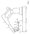
- FIG. 1 shows a hemming device 1 of a first embodiment.
- a roller type hemming device 1 is exemplified.
- the hemming device 1 comprises a multi-axes type robot hand 2 (a polar coordinate type multi-joint robot), a lower die 5 for supporting a work W, and a base 7 for securing these parts in a constant spatial relationship.
- a multi-axes type robot hand 2 a polar coordinate type multi-joint robot
- a lower die 5 for supporting a work W
- a base 7 for securing these parts in a constant spatial relationship.
- a bending roller R is rotatably attached to a distal end of the robot hand 2 via a support device 3.
- the robot hand 2 is operated based on a program that is previously memorized by teaching.
- the bending roller R is rolled along a bent portion We formed along a periphery of the work W, so that the bent portion We is bent to a folded state.
- hemming processing of the work W is performed.
- the work W is a door panel for an automobile and comprises an inner panel Wi and an outer panel Wo.
- the bent portion We that is formed along a periphery of the outer panel Wo is bent to a folded state, a periphery of the inner panel Wi is sandwiched therebetween.
- the panels Wo and Wi are integrated.
- the work W is placed on an upper surface 5a of the lower die 5 and secured in a desired position by fixture members 6-6.
- FIG. 2 is a plan view illustrating a condition in which the bending roller R rolls on the bent portion We of the work W (the outer panel Wo), thereby bending the bent portion We.
- the "plan view” corresponds to a view that is seen in the direction of Arrow H in FIG. 1, that is, a view that is seen in the direction perpendicular to the bent portion We that is folded.
- an arrow-tipped line R1 indicates a rolling direction (moving direction) of the bending roller R.
- the arrow-tipped line that indicates the direction of the rolling direction of the bending roller R will also be referred to as a rolling direction R1.
- the rolling direction R1 of the bending roller R corresponds to a tangent line at the bent portion We having an arcuate shape.
- the rolling direction of the bending roller R corresponds to a straight line parallel to the bent portion.
- a line R2 indicates a normal line perpendicular to the rolling direction R1
- a line R3 represents an axis of rotation of the bending roller R.
- the axis of rotation R3 is inclined at an angle 81 relative to the normal line R2 when shown in a plan view.
- the axis of rotation R3 is inclined relative to the normal line R2 such that one end of the roller R corresponding to a folded edge Wee of the bent portion We that is folded may form a rearward end when viewed in the rolling direction.
- the axis of rotation R3 of the bending roller R is set, so as to be parallel to the bent portion We that is folded, when laterally viewed as indicated by Arrow Y in FIG. 2.
- This arrangement is identical to the arrangement in a conventional final-bending step.
- the bending roller R moves in an inclined position and rolls on the bent portion We of a work W that is previously bent at an angle of approximately 90° by flanging processing. Therefore, it is possible to complete the hemming processing in one bending step without performing a conventional pre-bending step and without producing buckling in the bent portion We.
- the bending roller R rolls on the bent portion We in a posture that the axis of rotation R3 thereof is rearwardly inclined at an angle ⁇ 1 relative to the rolling direction R1 at a side of the folded edge Wee of the bent portion We that is folded. Therefore, a portion of a pressing force of the bending roller R is applied to the folded edge Wee of the bent portion We as a force component (side pressure) that presses the bent portion We in its bending direction.
- the bent portion We will be subjected to a pressing force in a direction of its surface and a pressing force (side pressure) in the direction (lateral direction) perpendicular to the surface. Therefore, even if the bending roller R rolls on the bent portion We in the same posture as that in the final-bending step of the conventional hemming device, the bent portion We is bent to a folded state as shown by the chain double-dashed line in FIG. 19 without producing buckling. Thus, it is possible to bend the bent portion We to the folded state without performing the conventional pre-bending step and without producing buckling in the bent portion We, to thereby complete the hemming processing.
- the pre-bending step is performed in a posture that in a side view, the axis of rotation R3 of the bending roller R is inclined at an angle of approximately 45° , and then an additional vending step is again performed in a posture that in a side view, the axis of rotation R3 is positioned parallel to the bent portion We that is folded.
- the axis of rotation R3 of the bending roller R is maintained in the same posture (the posture that the axis of rotation is positioned parallel to the bent portion We that is folded) as the conventional final-bending step in a side view and is inclined in a desired direction relative to the rolling direction in a plan view.
- the inclination angle 61 can be modified in accordance with the bent angle that is formed by the flanging processing (the angle relative to the portion along the upper surface 5a of the lower die 5; hereinafter referred to as a flange angle ⁇ 2; see FIG. 19).
- a flange angle ⁇ 2 the angle relative to the portion along the upper surface 5a of the lower die 5; hereinafter referred to as a flange angle ⁇ 2; see FIG. 19.
- the flange angle ⁇ 2 is an angle of approximately 60-80°
- the inclination angle ⁇ 1 is set to an angle of approximately 10-15°
- the inclination angle ⁇ 2 is set to an angle of approximately 80-100°
- the inclination angle ⁇ 2 is set to an angle of approximately 20-30° .
- the inclination angle ⁇ 1 can be variously modified based on the diameter of the bending roller R, the shape of the bent portion We, or other such elements.
- cylindrical bending roller R having a fixed diameter is used, for example, as shown in FIGS. 4 and 5, a tapered bending roller RT having an unfixed diameter can be used in order to bend the bent portion We from the unfolded state to the folded state in one rolling step.
- the bending roller RT is positioned such that its small diameter side corresponds to the folded edge of the bent portion We that is folded, and the axis of rotation R3 thereof is positioned such that a bending surface of the roller (an edge line that contacts the bent portion) is parallel to the bent portion We when the bending step is completed.
- the pressing force of the bending roller acts on an edge of the bent portion as a force component (side pressure) that presses the bent portion We in its bending direction.
- the bent portion can be bent to the folded state without producing buckling. Therefore, similar to the bending roller R, the tapered bending roller RT can also bend the bent portion We from the unfolded state to the folded state in one rolling step. As a result, it is possible to drastically reduce the time required to perform the hemming processing.
- This embodiment corresponds to an embodiment described in claim 2 or 4.
- the axis of rotation R3 of the bending roller RT can be inclined at, for instance, angle ⁇ 1 relative to the normal line R2 that is perpendicular to the rolling direction R1 in a plan view.
- a force component in the direction of Arrow S of the pressing force that is applied to the bent portion We via the bending roller R (the pressing force that is applied along a direction of a surface of the bent portion We, that is, the pressing force that may produce buckling in the conventional method) is applied to the bent portion We as a force (side pressure S) that presses the bent portion We in the bending direction.
- the bent portion We is reliably bent to the folded state without producing buckling.
- the tapered bending roller RT having an unfixed diameter is positioned such that the small diameter side corresponds to the folded edge Wee of the bent portion We that is folded and is rolled in the direction of Arrow R1 along the bent portion We in a condition that the axis of rotation R3 coincides with the normal line R2, the direction that the bending roller RT tends to roll (the direction of rotation) corresponds to the direction of Arrow C (the direction perpendicular to the edge line E of the circumferential surface). That is, the direction of rotation C corresponds to a direction that is inclined at angle ⁇ 3 relative to the rolling direction R1.
- the angle ⁇ 3 corresponds to an inclination angle of the circumferential surface (edge line E) relative to the axis of rotation R3. Therefore, the bending roller RT is also rolled along the bent portion We while sliding in the direction opposite to the direction of Arrow S.
- a force component in the direction of Arrow S of the pressing force that is applied to the bent portion We via the bending roller R (the pressing force that is applied along the direction of the surface of the bent portion We, that is, the pressing force that may produce buckling in the conventional method) is applied to the bent portion We as the force (side pressure S) that presses the bent portion We in the bending direction.
- the bent portion We is reliably bent to the folded state without producing buckling.
- the side pressure S can be increased, if the axis of rotation R3 of the roller is inclined at an angle ⁇ 1 relative to the normal line R2 at a side of the folded edge Wee of the bent portion We that is folded.
- a press type hemming device 10 is exemplified.
- the hemming device 10 of the third embodiment is illustrated in FIG. 8.
- the hemming device 10 comprises an upper die 11 that moves up and down, a lower die 12 on which the work W is seated, a bending blade 14 attached to the upper die 11 via an X-axis sliding device 13, and a cam die 15 for moving the bending blade 14 in a direction of the X-axis.
- the work W and the lower die 12 are the same members as those used in the first embodiment.
- the upper die 11 is moved upwardly or downwardly by means of a lifting device that is actuated by a hydraulic cylinder (not shown).
- the X-axis sliding device 13 is attached to the lower surface of the upper die 11. Further, in this specification, the X-axis direction will be referred to as the horizontal direction (the right-to-left direction in FIG. 8).
- the X-axis sliding device 13 comprises a base 13d, a compressing spring 13e that is sandwiched between the base 13d and the upper die 11, and a follower 13g rotatably attached to the base 13d via a bracket 13f.
- the base 13d can be freely slid in the X-axis direction by means of a sliding mechanism 13c.
- the sliding mechanism 13c comprises a slide rail 13a and a sliding member 13b that moves therealong.
- the base 13d is biased by means of the compressing spring 13e in the rightward direction in FIG. 8. Rightward movement of the base 13d is restricted by a stopper 13h. Further, the X-axis sliding device 13 does not have any special driving source for sliding the base 13d.
- the bracket 13f downwardly extends from the lower surface of the base 13d, and the follower 13g is rotatably retained on the proximal end thereof at a desired distance below the upper side 11.
- the bending blade 14 is attached to the lower surface of the base 13d and downwardly projects.
- the bent portion We of the work W is positioned beneath the bending blade 14.
- the cam die 15 is placed beneath the follower 13g and is seated on and secured to a mount 15b at a desired height.
- the hemming device 10 of the third embodiment and the hemming method by utilizing such a device it is also possible to bend the bent portion We from the unfolded state to the folded state by an angle of approximately 90° by a single downward motion (one shot) of the upper die 11. Therefore, it is possible to complete hemming processing without performing the conventional pre-bending step.
- the follower 13g contacts a cam surface 15a of the cam die 15. Thereafter, when the upper die 11 is further lowered while maintaining this contacting state, the follower 13g slidably contacts the cam surface 15a, so that the base 13d slides along the X-axis in the leftward direction in the drawing against the spring force of the compressing spring 13e.
- the bending blade 14 moves along an arcuate trajectory toward a combined direction (downwardly inclined direction) of a lowering direction (vertical direction) of the upper die 11 and an X-axis direction (horizontal direction). As shown in FIG. 9, after the bending blade 14 begins to move toward the downwardly inclined direction, an edge of the bending blade 14 contacts the edge of the bent portion We of the work W.
- the bending blade 14 After the edge of the bending blade 14 contacts the bent portion We, when the upper die 11 is further lowered and the follower 13g slidably contacts the cam surface 15a of the cam die 15, the bending blade 14 is moved leftwardly along the X-axis by means of the X-axis sliding device 13c. As a result, the bending blade 14 moves in the downwardly inclined direction along the arcuate trajectory. This motion is illustrated in FIG. 10. Because the bending blade 14 moves along such an arcuate trajectory, the bent portion We is downwardly pressed while being subjected to the pressing force in the bending direction (leftward direction along the X-axis). Therefore, the bent portion We is bent without producing buckling.
- the cam surface 15a is positioned such that the follower 13g is disengaged from the edge of the cam surface 15a when the bending of the bent portion We reaches its final stage (when it is bent, for example, by an angle of 45° or more from the unfolded state toward the folded state).
- FIG. 10 shows a condition that the bent portion We is bent to the folded state.
- the light arrow in FIG. 10 shows movement of the bending blade 14 that moves in the downwardly inclined direction along the arcuate trajectory and subsequently moves downwardly in the vertical direction.
- the upper die 11 When the upper die 11 has reached a lowermost position and the bent portion We is completely bent to the folded state, the upper die 11 begins to move upwardly.
- the bending blade 14 and the follower 13g move upwardly along a path opposite to the path along which they move when the upper die 11 is moved downwardly.
- the follower 13g reaches the cam surface 15a, the bending blade 14 moves upwardly while sliding rightwardly along the X-axis by means of the spring force of the compressing spring 13e of the X-axis sliding device 13.
- the bending blade 14 moves in the downwardly inclined direction along the arcuate trajectory. Therefore, the bent portion We can be bent to the folded state without producing buckling.
- the edge of the bending blade 14 may have a variety of shapes.
- a bending blade 16 shown in FIG. 11 has a flat beveled portion 16a that is formed in its edge.
- a bending blade 17 shown in FIG. 12 has a rounded convex portion 17a that is formed in its edge.
- a bending blade 18 shown in FIG. 13 has a shouldered concave portion 18a that is formed in its edge.
- a bending blade 19 shown in FIG. 14 has a rounded concave portion 19a that is formed in its edge.
- the edge 14a of the bending blade 14 shown in FIGS. 9 and 10 is not specifically changed and has a normal shape.
- the bending blade 14 moves leftwardly along the X-axis (inwardly in the bending direction), so that the edge 14a thereof is laterally forced against the bent portion We. Therefore, when the bending blade 14 moves leftwardly along the X-axis, the bending blade 14 bends the bent portion We while sliding (relatively moving) the edge 14a thereof toward the edge of the bent portion We along the surface thereof.
- the cam surface 15a can be designed such that when the bent portion We is progressively bent and is bent by an angle of approximately 45° , the follower 13g is disengaged therefrom and the edge 14a of the bending blade 14 is disengaged from the edge of the bent portion We, whereby the bending blade 14 moves downwardly in the vertical direction without moving along the X-axis. In this case, it is possible to reliably and attractively bend the bent portion We.
- the bending blade 18 shown in FIG. 13 or the bending blade 19 shown in FIG. 14 it is possible to substantially prevent the bending blade 18 or 19 from sliding along the bent portion We.
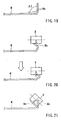
- the bending blade 18 shown in FIG. 15 it is possible to move the bending blade 18 in the downwardly inclined direction in a condition that the edge of the bent portion We is received within the concave portion 18a (a condition shown in the uppermost drawing of FIG. 15), as shown in the light arrow in the drawing.
- the bending blade 18 can be prevented from moving (sliding) relative to the bent portion We until the bent portion We is bent by approximately 45° (a condition shown in the central drawing of FIG. 15).
- the bending blade 18 moves downwardly only in the vertical direction without moving along the X-axis, as shown in the light arrow of the drawing (a condition shown in the lowermost drawing of FIG. 15).
- the bending blade 18 can be prevented from sliding relative to the bent portion We until the bent portion We is completely folded.
- the beveled portion 16a of the bending blade 16 shown in FIG. 11 and the rounded convex portion 17a of the bending blade 17 shown in FIG. 12 do not have a lesser slide-preventing performance than the bending blades 18 and 19. Therefore, these bending blades 16 and 17 will cause a certain amount of sliding motion relative to the bent portion We. However, these bending blades 16 and 17 may have a greater slide-preventing performance than the bending blade 14.
- a hemming device 30 of a fourth embodiment is shown in FIG. 16.
- the hemming device 30 of the fourth embodiment has a mechanism for moving a bending blade 33 along the X-axis, which mechanism is different from that in the hemming device 10 of the third embodiment.
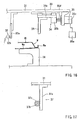
- the hemming device comprises an upper die 31, an upper-die vertical position detector 32 for detecting the vertical position of the upper die 31, a bending blade 33, an X-axis sliding device 34 for moving the bending blade 33 along the X-axis, a single-axis driver 35 for driving the X-axis sliding device 34, and a lower die 36 for supporting the work W.
- the upper die 31 is moved upwardly or downwardly by means of a lifting device that is actuated by a hydraulic cylinder (not shown).
- the upper-die vertical position detection device 32 is a so-called linear scale that comprises a sensing beam 32a attached to the upper die 31 and a position sensor 32b for detecting the position of the sensing beam.
- the position of the sensing beam 32a detected by the position sensor 32b, i.e., the position of the upper die 31 is input into an NC controller 35a of the single-axis driver 35.
- the X-axis sliding device 34 has the same construction as the X-axis sliding device 13c of the third embodiment and includes a base 34a.
- the bending blade 33 and a nut 35b of the single-axis driver 35 are attached to the lower surface of the base 34a.
- the single-axis driver 35 comprises a servo motor 35c, a threaded shaft 35d that is rotated by the servo motor, the nut 35b which meshes the threaded shaft 35d, and the NC controller 35a for controlling the rotation of the servo motor 35c.
- the hemming device 30 thus constructed, when the upper die 31 is lowered to a certain position, such a position is detected by the upper-die vertical position detection device 32.
- the detection signal output by the upper-die vertical position detection device 32 is input into the NC controller 35a.
- the servo motor 35c is actuated, thereby rotating the threaded shaft 35d.
- the base 34a of the X-axis sliding device 34 moves leftwardly along the X-axis because the threaded shaft 35d meshes the nut 35b.
- the bending blade 33 is lowered in the downwardly inclined direction along an arcuate trajectory. At this time, an edge of the bending blade 33 contacts the bent portion We of the work W. Thereafter, when the upper die 31 is further lowered, the bending blade 33 is lowered along the arcuate trajectory. As a result, similar to said third embodiment, the bent portion We is folded from the unfolded state to the folded state.
- the bending blade 33 is lowered in the downwardly inclined direction along the arcuate trajectory, the bending blade 33 can apply a lateral force (side pressure) against the bent portion We. Therefore, it is possible to bend the bent portion to the folded state without performing the conventional pre-bending step in one shot. As a result, similar to the third embodiment, it is possible to omit the die for the conventional pre-bending.
- the program can be changed by operating an input device (ten-key pad or pendant) provided to the NC controller 35a, in order to change or adjust the motion of the bending blade 33. Therefore, the hemming device 30 can be applied to the work W that has a variety of shapes. Thus, it is possible to increase versatility of the device.
- an input device ten-key pad or pendant
- the upper-die vertical position detection device 32 may be replaced with that as shown in FIG. 17.
- An upper-die vertical position detection device 37 shown in FIG. 17 comprises a rack 37a attached to the upper die 31, a pinion 37b meshed with the rack 37a, and an encoder 37c.
- the pinion 37b is attached to, for example, the lower die 36.
- the encoder 37c has an output shaft, which shaft is coupled to the pinion 37b.
- the hemming method of the present invention can also be performed by utilizing a dual-axis-controlled hemming device 40 shown in FIG. 18. Unlike the third and fourth embodiments, the hemming device 40 of a fifth embodiment does not require the upper die 11 or 31.
- the hemming device 40 of the fifth embodiment comprises a lower die 41 for supporting the work W, a lifting base 42 that is supported on a side surface of the lower die 41 so as to be slidable in the vertical direction, a vertical driving device 43 for raising and lowering the lifting base 42, an X-axis sliding device 45 disposed on an upper portion of the lifting base 42 for moving a bending blade 44 along the X-axis, and a lateral driving device 46 for sliding a base 45a of the X-axis sliding device 45 along the X-axis.
- the lifting device 42 is supported by means of a rail 42a that is vertically attached to the side surface of the lower die 41, so as to be slidable in the vertical direction.
- the vertical driving device 43 comprises a base 43a that is attached to the side surface of the lower die 41 and projects therefrom, a servo motor 43b attached to the base 43a, a drive pulley 43c attached to an output shaft of the motor, a threaded shaft 43e rotatably supported on the base 43a via bearings 43d, 43d, a driven pulley 43f attached to the lower end portion of the threaded shaft 43e, and a belt 43g engaged with the driven pulley 43f and the drive pulley 43c.
- the upper end portion of the threaded shaft 43e is meshed with a nut 43h that is attached to the lower end portion of the lifting base 42.
- the X-axis sliding device 45 has the same construction as that of the the third and fourth embodiments.
- the sliding device 46 comprises a support bracket 46a vertically attached to the upper surface of the lifting base 42, a servo motor 46b attached to the upper portion of the support bracket 46a, a drive pulley 46c attached to an output shaft of the motor, a threaded shaft 46e rotatably supported on the support bracket 46a via bearings 46d, 46d, a driven pulley 46f attached to one end of the threaded shaft 46e, and a belt 46g engaged with the driven pulley 46f and the drive pulley 46c.
- the other end of the threaded shaft 46e is meshed with a nut 46h that is attached to the base 45a of the X-axis sliding device 45.
- the bending blade 44 is attached to the left-side surface of the base 45a.
- the bending blade 44 is moved in the downwardly inclined direction along an arcuate or linear trajectory, to thereby bend the bent portion We of the work W from its unfolded state to its folded state without producing buckling. Therefore, similar to the first to fourth embodiments, it is possible to complete hemming processing by a single pressing operation of the bending blade 44 without performing the conventional pre-bending step. Therefore, it is possible to omit the die for the conventional pre-bending step.
- a slide mechanism comprising a slide rail and a sliding member that moves along the slide rail is exemplified.
- a link mechanism in order to move the bending blades 33 and 44 in the X-axis direction or in the vertical direction
Landscapes
- Engineering & Computer Science (AREA)
- Mechanical Engineering (AREA)
- Bending Of Plates, Rods, And Pipes (AREA)
- Automobile Manufacture Line, Endless Track Vehicle, Trailer (AREA)
Applications Claiming Priority (3)
| Application Number | Priority Date | Filing Date | Title |
|---|---|---|---|
| JP2001335397 | 2001-10-31 | ||
| JP2001335397A JP3623474B2 (ja) | 2001-10-31 | 2001-10-31 | ヘミング加工装置およびヘミング加工方法 |
| PCT/JP2002/010390 WO2003037541A1 (en) | 2001-10-31 | 2002-10-04 | Device and method for hemming processing |
Publications (2)
| Publication Number | Publication Date |
|---|---|
| EP1445043A1 true EP1445043A1 (de) | 2004-08-11 |
| EP1445043A4 EP1445043A4 (de) | 2006-08-02 |
Family
ID=19150391
Family Applications (1)
| Application Number | Title | Priority Date | Filing Date |
|---|---|---|---|
| EP02768145A Withdrawn EP1445043A4 (de) | 2001-10-31 | 2002-10-04 | Vorrichtung und verfahren zum falzverbinden |
Country Status (6)
| Country | Link |
|---|---|
| US (1) | US20040035172A1 (de) |
| EP (1) | EP1445043A4 (de) |
| JP (1) | JP3623474B2 (de) |
| KR (1) | KR20040038890A (de) |
| CN (1) | CN1525891A (de) |
| WO (1) | WO2003037541A1 (de) |
Cited By (3)
| Publication number | Priority date | Publication date | Assignee | Title |
|---|---|---|---|---|
| DE102006010469A1 (de) * | 2006-03-07 | 2007-09-13 | GM Global Technology Operations, Inc., Detroit | Bördeleinrichtung sowie Verfahren zum Rollbördeln von Werkstücken |
| DE102006028833A1 (de) * | 2006-06-21 | 2007-12-27 | Thyssenkrupp Drauz Nothelfer Gmbh | Verfahren zum Falzen eines Randes eines Blechbauteils, insbesondere eines Blechbauteils einer Kfz.-Karosserie |
| EP2108466A3 (de) * | 2005-12-05 | 2010-01-27 | Honda Motor Co., Ltd. | Umbördelverfahren und Umbördelvorrichtung |
Families Citing this family (25)
| Publication number | Priority date | Publication date | Assignee | Title |
|---|---|---|---|---|
| FR2874185B1 (fr) * | 2004-08-16 | 2006-11-17 | Abb Mc Soc Par Actions Simplif | Outil de sertissage |
| US7124611B2 (en) | 2004-10-08 | 2006-10-24 | Valiant Corporation | Roller hemming machine |
| JP4870479B2 (ja) * | 2005-06-21 | 2012-02-08 | 本田技研工業株式会社 | ヘミング加工方法及びヘミング加工装置 |
| US20070240474A1 (en) * | 2005-07-05 | 2007-10-18 | Abb France | Crimping Tool |
| FR2903030B1 (fr) * | 2006-07-03 | 2009-12-04 | Process Conception Ing Sa | Dispositif d'assemblage de deux panneaux de tole par sertissage |
| CN100484657C (zh) * | 2007-12-19 | 2009-05-06 | 中国重型机械研究院 | 多功能液压翻边机翻边工艺 |
| KR100872601B1 (ko) * | 2008-03-14 | 2008-12-08 | (주)우신시스템 | 차량용 패널의 헤밍장치 |
| US20090235713A1 (en) * | 2008-03-24 | 2009-09-24 | Hirotec America, Inc. | Magnetically actuated roller head |
| US20100281940A1 (en) * | 2009-03-12 | 2010-11-11 | Harrow Aaron E | Vertical air compliant hemming head |
| CN101530881B (zh) * | 2009-04-16 | 2012-05-23 | 上海交通大学 | 涵盖多种包边方式的机器人滚压包边成形特征模具 |
| WO2011025697A1 (en) * | 2009-08-26 | 2011-03-03 | Hirotec America, Inc. | Horizontally stacked hemming press |
| JP4795462B2 (ja) * | 2009-11-12 | 2011-10-19 | ファナック株式会社 | 力センサを搭載したロボットマニピュレータを用いたロールヘム加工装置 |
| CN102125949B (zh) * | 2010-11-29 | 2013-02-13 | 上海华普汽车模具制造有限公司 | 一种包边机的直接终包机构 |
| JP5932411B2 (ja) * | 2012-03-13 | 2016-06-08 | 本田技研工業株式会社 | ローラヘミング装置及びローラヘミング方法 |
| US9630235B2 (en) * | 2013-04-24 | 2017-04-25 | Nissan Motor Co., Ltd. | Roller hemming processing device and roller hemming processing method |
| CN103357767B (zh) * | 2013-07-05 | 2015-04-22 | 湖南三一智能控制设备有限公司 | 螺旋仓身的制造方法及螺旋仓机系统 |
| JP5971226B2 (ja) * | 2013-11-01 | 2016-08-17 | 株式会社安川電機 | ロボットシステムおよび被加工物の製造方法 |
| CN106555792B (zh) * | 2015-09-24 | 2018-11-16 | 长城汽车股份有限公司 | 板件的包边模块、包边模具和包边方法 |
| CN106424264B (zh) * | 2016-10-13 | 2018-12-04 | 山东鸿民金属成型科技股份有限公司 | 一种生产叠边型材的设计工艺 |
| CN107839674B (zh) * | 2017-09-28 | 2019-11-05 | 浙江零跑科技有限公司 | 新能源车制动装置及制动方法 |
| EP3856429A4 (de) * | 2018-09-27 | 2022-06-22 | Inno-Spin LLC | Mehrachsige walzformverfahren, systeme und produkte |
| CN113198932A (zh) * | 2021-04-23 | 2021-08-03 | 郑州多元汽车装备有限公司 | 一种轮罩蒙皮预包边设备 |
| US11498112B1 (en) * | 2021-07-14 | 2022-11-15 | DRiV Automotive Inc. | Roller press assembly and method |
| CN115178627A (zh) * | 2022-08-15 | 2022-10-14 | 楚天科技股份有限公司 | 一种柱状筒体卷边方法及装置 |
| CN117299895A (zh) * | 2023-09-05 | 2023-12-29 | 东莞市永强汽车制造有限公司 | 一种厢式车后厢门用铰链轴的弯制装置以及弯制方法 |
Family Cites Families (15)
| Publication number | Priority date | Publication date | Assignee | Title |
|---|---|---|---|---|
| US3680346A (en) * | 1971-01-04 | 1972-08-01 | Rudolph R Wilcox | Crimping tool |
| JPS5039623B2 (de) * | 1972-09-18 | 1975-12-18 | ||
| US4060046A (en) * | 1976-01-30 | 1977-11-29 | Eckold Gerd Juergen | Hand tool |
| JPS55122636A (en) * | 1979-03-15 | 1980-09-20 | Takatsu Seisakusho:Kk | Hamming device |
| JPS57124524A (en) * | 1981-01-27 | 1982-08-03 | Nissan Motor Co Ltd | Hemming work method |
| JPS61262432A (ja) * | 1985-05-15 | 1986-11-20 | Torai Eng Kk | ロ−ラ−式ヘミング装置およびその方法 |
| US4827595A (en) * | 1985-12-05 | 1989-05-09 | Utica Engineering Company | Method for hemming overlapped sheet material |
| JP2579530B2 (ja) * | 1988-06-24 | 1997-02-05 | マツダ株式会社 | ヘミング成形方法 |
| JP2675347B2 (ja) * | 1988-09-06 | 1997-11-12 | マツダ株式会社 | ヘミング成形装置 |
| JPH0318925U (de) * | 1989-07-06 | 1991-02-25 | ||
| JP2693282B2 (ja) * | 1991-03-20 | 1997-12-24 | トライエンジニアリング株式会社 | ローラー式ヘミング装置と該装置を用いたローラー式ヘミング加工方法 |
| US5740691A (en) * | 1994-02-14 | 1998-04-21 | Western Atlas U.K. Limited | Hemming machine |
| JP3532746B2 (ja) * | 1997-10-28 | 2004-05-31 | 株式会社東洋技研 | ヘミング加工装置 |
| US6161410A (en) * | 1998-08-11 | 2000-12-19 | Unova Ip Corp. | Multi-axis roller hemmer |
| JP2001062530A (ja) * | 1999-08-31 | 2001-03-13 | Sango Co Ltd | ヘミング加工装置 |
-
2001
- 2001-10-31 JP JP2001335397A patent/JP3623474B2/ja not_active Expired - Lifetime
-
2002
- 2002-10-04 CN CNA028027566A patent/CN1525891A/zh active Pending
- 2002-10-04 KR KR10-2003-7004105A patent/KR20040038890A/ko not_active Withdrawn
- 2002-10-04 WO PCT/JP2002/010390 patent/WO2003037541A1/ja not_active Ceased
- 2002-10-04 EP EP02768145A patent/EP1445043A4/de not_active Withdrawn
- 2002-10-04 US US10/398,420 patent/US20040035172A1/en not_active Abandoned
Cited By (8)
| Publication number | Priority date | Publication date | Assignee | Title |
|---|---|---|---|---|
| EP2108466A3 (de) * | 2005-12-05 | 2010-01-27 | Honda Motor Co., Ltd. | Umbördelverfahren und Umbördelvorrichtung |
| US8272243B2 (en) | 2005-12-05 | 2012-09-25 | Honda Motor Co., Ltd. | Hemming working method and working apparatus |
| CN101811163B (zh) * | 2005-12-05 | 2013-12-25 | 本田技研工业株式会社 | 折边加工方法和折边加工设备 |
| US8914964B2 (en) | 2005-12-05 | 2014-12-23 | Honda Motor Co., Ltd. | Hemming working method and working apparatus |
| DE102006010469A1 (de) * | 2006-03-07 | 2007-09-13 | GM Global Technology Operations, Inc., Detroit | Bördeleinrichtung sowie Verfahren zum Rollbördeln von Werkstücken |
| DE102006028833A1 (de) * | 2006-06-21 | 2007-12-27 | Thyssenkrupp Drauz Nothelfer Gmbh | Verfahren zum Falzen eines Randes eines Blechbauteils, insbesondere eines Blechbauteils einer Kfz.-Karosserie |
| WO2007147692A1 (de) * | 2006-06-21 | 2007-12-27 | Thyssenkrupp Drauz Nothelfer Gmbh | Verfahren zum falzen eines randes eines blechbauteils, insbesondere eines blechbauteils einer kfz.-karosserie |
| US8302444B2 (en) | 2006-06-21 | 2012-11-06 | Thyssenkrupp Drauz Nothelfer Gmbh | Method for folding an edge of a sheet component in particular a sheet component of a motor vehicle chassis |
Also Published As
| Publication number | Publication date |
|---|---|
| US20040035172A1 (en) | 2004-02-26 |
| JP2003136161A (ja) | 2003-05-14 |
| EP1445043A4 (de) | 2006-08-02 |
| KR20040038890A (ko) | 2004-05-08 |
| JP3623474B2 (ja) | 2005-02-23 |
| WO2003037541A1 (en) | 2003-05-08 |
| CN1525891A (zh) | 2004-09-01 |
Similar Documents
| Publication | Publication Date | Title |
|---|---|---|
| US20040035172A1 (en) | Device and method for hemming processing | |
| US20080250835A1 (en) | Roll Hemming Method and Roll Hemming Apparatus | |
| US5746082A (en) | Thin sheet forming die assembly including lower die cylindrical member having varied diameters | |
| KR101309518B1 (ko) | 롤러 헤밍 장치 | |
| JP2000051971A (ja) | ヘミング加工装置およびヘミング加工方法 | |
| EP0979692A2 (de) | Mehrachsiges Rollenfalzvorrichtung | |
| JPH0760370A (ja) | ヘミング加工装置 | |
| JP2010194568A (ja) | ヘミング装置およびヘミング加工方法 | |
| US11253902B2 (en) | Hemming apparatus | |
| JP4495184B2 (ja) | ヘミング加工装置及びヘミング加工方法 | |
| CN108015139B (zh) | 辊卷边装置及辊卷边方法 | |
| JP4943666B2 (ja) | ロールヘミング加工方法及び加工装置 | |
| JP2002102957A (ja) | ロールヘミング装置及びそれを用いたロールヘミング加工方法 | |
| JPH0768324A (ja) | ヘミング加工装置 | |
| JPH08164433A (ja) | ヘミング加工装置 | |
| JPH0747429A (ja) | ヘミング加工装置 | |
| GB2344546A (en) | Bend forming apparatus | |
| JP6111153B2 (ja) | 湾曲長尺材の製造方法、及び湾曲長尺材製造装置 | |
| JP3452165B2 (ja) | 板金ワークのヘミング加工方法 | |
| JP2022541069A (ja) | 板状工作物、特に金属板を加工するためのツール及び方法 | |
| JPH0513639U (ja) | リベツトのカシメ装置 | |
| JP4822485B2 (ja) | ヘミング装置 | |
| US7204118B2 (en) | Hemming tool die assembly | |
| JP2022052520A (ja) | ローラヘム加工装置 | |
| JPH0618653Y2 (ja) | プレス型構造 |
Legal Events
| Date | Code | Title | Description |
|---|---|---|---|
| PUAI | Public reference made under article 153(3) epc to a published international application that has entered the european phase |
Free format text: ORIGINAL CODE: 0009012 |
|
| 17P | Request for examination filed |
Effective date: 20040203 |
|
| AK | Designated contracting states |
Kind code of ref document: A1 Designated state(s): AT BE BG CH CY CZ DE DK EE ES FI FR GB GR IE IT LI LU MC NL PT SE SK TR |
|
| A4 | Supplementary search report drawn up and despatched |
Effective date: 20060629 |
|
| STAA | Information on the status of an ep patent application or granted ep patent |
Free format text: STATUS: THE APPLICATION IS DEEMED TO BE WITHDRAWN |
|
| 18D | Application deemed to be withdrawn |
Effective date: 20060929 |