EP1445133A2 - Dispositif de climatisation d'un véhicule automobile - Google Patents
Dispositif de climatisation d'un véhicule automobile Download PDFInfo
- Publication number
- EP1445133A2 EP1445133A2 EP04002482A EP04002482A EP1445133A2 EP 1445133 A2 EP1445133 A2 EP 1445133A2 EP 04002482 A EP04002482 A EP 04002482A EP 04002482 A EP04002482 A EP 04002482A EP 1445133 A2 EP1445133 A2 EP 1445133A2
- Authority
- EP
- European Patent Office
- Prior art keywords
- cool air
- warm air
- air passage
- outlet
- flow holes
- Prior art date
- Legal status (The legal status is an assumption and is not a legal conclusion. Google has not performed a legal analysis and makes no representation as to the accuracy of the status listed.)
- Granted
Links
Images




Classifications
-
- B—PERFORMING OPERATIONS; TRANSPORTING
- B60—VEHICLES IN GENERAL
- B60H—ARRANGEMENTS OF HEATING, COOLING, VENTILATING OR OTHER AIR-TREATING DEVICES SPECIALLY ADAPTED FOR PASSENGER OR GOODS SPACES OF VEHICLES
- B60H1/00—Heating, cooling or ventilating devices
- B60H1/00007—Combined heating, ventilating, or cooling devices
- B60H1/00021—Air flow details of HVAC devices
- B60H1/00064—Air flow details of HVAC devices for sending air streams of different temperatures into the passenger compartment
-
- B—PERFORMING OPERATIONS; TRANSPORTING
- B60—VEHICLES IN GENERAL
- B60H—ARRANGEMENTS OF HEATING, COOLING, VENTILATING OR OTHER AIR-TREATING DEVICES SPECIALLY ADAPTED FOR PASSENGER OR GOODS SPACES OF VEHICLES
- B60H1/00—Heating, cooling or ventilating devices
- B60H1/00007—Combined heating, ventilating, or cooling devices
- B60H1/00021—Air flow details of HVAC devices
- B60H2001/00078—Assembling, manufacturing or layout details
- B60H2001/00092—Assembling, manufacturing or layout details of air deflecting or air directing means inside the device
Definitions
- the present invention relates to an airconditioning system for automobiles, having a baffle plate located at a position at which warm air and cool air to be mixed together join each other.
- baffle plate 11 provided in an airconditioning system for automobiles at a position at which a cool air passage and a warm air passage join to improve the air mixing performance by alternately generating a cool air layer and a warm air layer in the related art has made significant progress (see Japanese Unexamined Patent Publication No. 2002-59726).
- the automotive airconditioning system 1 having an evaporator 3 and a heater core 4 disposed in this order starting on the upstream side of the supplied air inside an airconditioning case 2 also includes an air mix shutter 5 which guides part of or all of the cool air having been cooled at the evaporator 3 to the upstream side of the heater core 4.
- the cool air guided into the heater core 4 is heated.
- the baffle plate 11 is disposed to mix the cool air and the warm air efficiently at a position at which a warm air passage 10 formed on the downstream side of the heater core 4 joins a cool air passage 6 through which cool air flows by bypassing the heater core 4.
- the cool air and the warm air are mixed with a high degree of reliability at the baffle plate 11 to achieve the required air temperature, and then the air achieving the desired temperature is let out through a defrost outlet 13, a vent outlet 14 or a foot outlet 15 in conformance to the selected outlet mode setting.
- the baffle plate 11 utilized in the automotive airconditioning system 1 includes a plurality of cool air flow holes 20 that guide the cool air from the cool air passage 6 toward the vent outlet 14 and a plurality of warm air guide grooves 21 formed perpendicular to the cool air flow holes 20 and having open ends on the outlet side, which guide the warm air from the warm air passage 10 toward the defrost outlet, as shown in FIG. 6. It also includes openings 23 formed toward the warm air passage with the surfaces of the cool air flow holes 20.
- the baffle plate 11 allows the warm air to flow into the cool air flow holes 20 via the openings 23 as well as into the warm air guide grooves 21 from the warm air passage 10 in a bilevel mode and a defrost-and-heat mode
- the cool air which flows fast, reaches a foot passage 19 extending to the foot outlet 15 to push back the warm air, preventing the warm air from flowing toward the foot passage 19.
- the temperature at the floor level does not rise readily. This gives rise to a problem in that a predetermined difference in the temperature cannot be achieved between the temperature at the floor level and the air let out through the vent outlet or the defrost outlet.
- an object of the present invention is to provide an airconditioning system for automobiles, having a baffle plate that achieves a smooth supply of warm air to a foot passage extending to a foot outlet in the bilevel mode and the defrost-and-heat mode.
- the baffle plate in an airconditioning system for automobiles according to the present invention having a baffle plate which is disposed at a position at which a cool air passage and a warm air passage join each other, the baffle plate includes a plurality of cool air flow holes that guide cool air from the cool air passage towards a vent outlet and a plurality of warm air guide grooves formed perpendicular to the cool air flow holes that guide warm air from the warm air passage toward a defrost outlet and are open to the outside, and the cool air flow holes each have an opening on the warm air passage side and each include a first cool air guide near the center thereof.
- the cool air is guided with the first cool air guides and a flow of cool air toward the vent outlet is created, which, in turn, makes it possible to allow the warm air to travel from the warm air passage to a foot passage extending to a foot vent without creating a cool air flow that will push back in the warm air even when the bilevel mode or the defrost-and-heat mode is selected.
- the desired degree of difference in the temperature can be achieved between the air let out through the foot outlet and the air let out through the vent outlet or between the air let out through the foot outlet and the air let out through the defrost outlet.
- the cool air flow holes may each be divided into two cool air flow holes by the first cool air guide, with one of the cool air flow holes separated from the other by the first cool air guide having an opening so as to communicate with the warm air passage, to achieve the object described above.
- an advantage is achieved in that with the flow regulated by the first cool air guide, the warm air is allowed to enter the one of the two separated cool air flow holes through the opening more readily.
- second cool air guides may be provided at the cool air flow holes on the side toward the defrost outlet.
- the second cool air guides work together with the first cool air guides to create a flow of cool air toward the vent outlet. It is to be noted that the first cool air guides and the second cool air guides both extend toward the vent outlet.
- a sound absorbing member may be mounted at the surfaces of the warm air guide grooves located toward the evaporator, and a baffle plate adopting such a structure does not become a source of noise since the noise of the cool air impacting the outer sides of the warm air guide grooves is absorbed by the sound absorbing member and also the noise of the coolant flowing from the evaporator, the noise of the air current cut off at the fins and the like are absorbed by the sound absorbing member.
- the baffle plate may be mounted at the airconditioning case via a means for fitting.
- the baffle plate can be utilized with a high degree of efficiency as a passage in the space inside the airconditioning case.
- the baffle plate may further include a means for displacement prevention.
- This means for displacement prevention which is provided to prevent the baffle plate from being rotated via the means for fitting used to mount the baffle plate at the airconditioning case, may be a displacement preventing plate formed at the airconditioning case or may be provided at the baffle plate and be made to engage with the airconditioning case.
- an evaporator 3 constituting a freezing cycle is installed longitudinally inside an airconditioning case 2.
- air supplied from an air blower (not shown) is cooled, and the cool air is supplied to a heater core 4 located on the downstream side relative to the evaporator.
- An air mix shutter 5 located at a cool air passage 6 on the downstream side relative to the evaporator 3, through which cool air flows, adjusts the volume of cool air flowing to the heater core 4 on the downstream side.
- the air mix shutter 5, which is disposed inside a guide groove 7 formed at the airconditioning case 2 so as to run across the cool air passage 6, is made to move up/down via a pinion 8 rotated with a drive force applied from the outside.
- Engine cooling water is supplied to the heater core 4 at which the cool air becomes heated as it passes through.
- the heater core 4 is located at a warm air passage 10 branching from the cool air passage 6.
- the warm air passage 10 joins the cool air passage 6 on its downstream side, and a baffle plate 11 is provided at the joining position to mix the cool air and the warm air efficiently.
- a defrost outlet 13, a vent outlet 14 and a foot outlet 15 are formed, and mode doors 16, 17 and 18 respectively provided at the outlets 13, 14 and 15 are controlled to open/close in correspondence to the selected outlet mode to let out the conditioned air into the cabin through the open outlets.
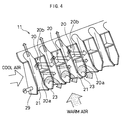
- the baffle plate 11 includes numerous cool air flow holes 20 extending from the side near the cool air passage 6 toward the vent outlet 14 and numerous warm air guide grooves 21, and the cool air flow holes 20 and warm air guide grooves 21 are formed alternately.
- a first guide 22 is formed so as to extend toward the vent outlet, and thus, the cool air flow hole 20 is divided by the first guide 22 into two separate cool air flow holes 20a and 20b.
- an opening 23 is formed at one of the two separate cool air flow holes, i.e., the cool air pass hole 20a, on the side toward the warm air passage 10, so as to communicate with the warm air passage 10 as well as with the cool air passage 6. For this reason, warm air is supplied into the cool air pass hole 20a, as well.
- the warm air guide grooves 21 are formed to extend from the side toward the warm air passage 10 to reach the defrost outlet 13 by intersecting the cool air flow holes 20 at a right angle, and each have an opening on the side toward the vent outlet 14.
- the warm air from the warm air passage 10 is guided toward the defrost outlet 13 through the warm air guide grooves 21 and also flows out in layers toward the vent outlet (toward the baffle plate downstream side) so that it is mixed with the layered cool air from the cool air flow holes 20 explained earlier to achieve the desired temperature. It is to be noted that the faster the warm air flows, the greater volume of warm air travels through the warm air guide grooves 21 toward the defrost outlet in proportion.
- second cool air guides 25 are formed at the cool air flow holes 20 on the side toward the defrost outlet 13, and the second cool air guides 25 work together with the first cool air guides 22 to create a cool air flow toward the vent outlet 14.
- the second cool air guides 25 are formed in an arc shape.
- the flows of the cool air and the warm air in the structure described above are now explained in reference to FIGS. 1 and 4.
- the air taken into the automotive airconditioning system 1 is cooled at the evaporator 3, and the volume of the cool air flowing to the heater core 4 is determined by the position to which the air mix shutter 5 is opened.
- the cool air passes through the heater core 4 where it is heated to become warm air, and the warm air is then mixed with the cool air via the baffle plate 11 to achieve the desired air temperature.
- the vent outlet 14 is opened to let out the temperature controlled air obtained by mixing the cool air and the warm air through the outlet 14.
- the vent outlet 14 and the foot outlet 15 are opened to achieve the cool air flow and the warm air flow shown in FIGS. 1 and 3.
- the cool air in particular, is guided via the first and second guides 22 and 25 to flow toward the vent outlet as indicated by the solid arrows and, as a result, the warm air from the warm air passage 10 is caused to flow into the cool air flow holes 20a located further forward, as indicated by the dotted arrows, to travel to a foot passage 19 which extends to the foot outlet 15.
- the temperature of the air let out through the foot outlet 15 can be raised relative to the temperature of the air let out through the vent outlet 14, thereby achieving a predetermined temperature difference.
- the defrost outlet 13 and the foot outlet 15 are opened, and the warm air is made to flow to the defrost outlet 13 through the warm air guide grooves 21.
- cool air flow is created to allow the cool air to be guided by the first and second cool air guides 22 and 25 toward the vent outlet 14, and the warm air is allowed to flow to the foot passage 19 extending to the foot outlet 15, thereby achieving the desired output temperature.
- a sound absorbing member 27 is attached to each warm air guide groove 21 on the side toward the cool air passage 6 (toward the evaporator) at the baffle plate 11.
- the baffle plate 11 is mounted at the airconditioning case 2 by fitting a pair of projections 29, which are formed at the side surfaces of the warm air guide grooves 21 on both ends, as shown in FIG. 2, at fitting holes 30 formed at the airconditioning case 2, as shown in FIG. 3.
- a means for displacement prevention is provided to prevent rotation of the baffle plate 11, which is mounted at the airconditioning system 1 with a means for fitting constituted of the projections 29.
- a displacement preventing plate 32 is formed at the airconditioning case 2, as shown in FIG. 1.
- the means for displacement prevention may be constituted by providing a retaining piece at the baffle plate 11, and in such a case, a means for engaging the retaining piece to the airconditioning case 2 is provided.
- a cool air flow toward the vent outlet is created by guiding the cool air with the first cool air guides.
- warm air is allowed to travel from the warm air passage to the foot passage which extends to the foot outlet to ensure that the temperature of the air let out through the foot outlet achieves a desired level in the bilevel mode and the defrost-and-heat mode. Consequently, the desired optimal temperature difference is achieved between the air let out through the foot outlet and the air let out through the vent outlet or between the air let out through the foot outlet and the air let out through the defrost outlet.
- the first cool air guides regulate the cool air flow, and allow the warm air to readily enter the cool air flow holes on one side through the openings.
- the second cool air guides work together with the first cool air guides to direct the flow of the cool air toward the vent outlet.
- the sound absorbing members mounted at the warm air guide grooves at the baffle plate absorb the noise of the cool air impacting the warm air guide grooves to prevent noise generation, and also absorbs any noise originating from other devices.
- the baffle plate is mounted at the airconditioning case 2 via the means for fitting and, as a result, the baffle plate can be utilized in an efficient manner as a passage running through the space inside the airconditioning case.
- the baffle plate is held securely in place by the means for displacement prevention and thus, the baffle plate can be mounted at the airconditioning case via the means for fitting without any risk of the baffle plate becoming displaced.
Landscapes
- Physics & Mathematics (AREA)
- Thermal Sciences (AREA)
- Engineering & Computer Science (AREA)
- Mechanical Engineering (AREA)
- Air-Conditioning For Vehicles (AREA)
Applications Claiming Priority (2)
| Application Number | Priority Date | Filing Date | Title |
|---|---|---|---|
| JP2003031904 | 2003-02-10 | ||
| JP2003031904A JP4172013B2 (ja) | 2003-02-10 | 2003-02-10 | 自動車用空調装置 |
Publications (3)
| Publication Number | Publication Date |
|---|---|
| EP1445133A2 true EP1445133A2 (fr) | 2004-08-11 |
| EP1445133A3 EP1445133A3 (fr) | 2005-06-29 |
| EP1445133B1 EP1445133B1 (fr) | 2007-03-28 |
Family
ID=32653036
Family Applications (1)
| Application Number | Title | Priority Date | Filing Date |
|---|---|---|---|
| EP20040002482 Expired - Lifetime EP1445133B1 (fr) | 2003-02-10 | 2004-02-04 | Dispositif de climatisation d'un véhicule automobile |
Country Status (3)
| Country | Link |
|---|---|
| EP (1) | EP1445133B1 (fr) |
| JP (1) | JP4172013B2 (fr) |
| DE (2) | DE602004005513T2 (fr) |
Cited By (16)
| Publication number | Priority date | Publication date | Assignee | Title |
|---|---|---|---|---|
| EP1733904A1 (fr) | 2005-06-17 | 2006-12-20 | Behr GmbH & Co. KG | Dispositif de climatisation pour véhicule comprenant une dérivation à air froid |
| EP2368732A3 (fr) * | 2010-03-15 | 2012-01-18 | Behr GmbH & Co. KG | Module de mélange pour une installation de chauffage, d'aération et/ou de climatisation |
| WO2012038246A1 (fr) * | 2010-09-23 | 2012-03-29 | Behr Gmbh & Co. Kg | Élément mélangeur et module mélangeur de deux flux d'air se croisant dans un appareil de climatisation |
| EP2489533A1 (fr) * | 2011-02-18 | 2012-08-22 | Valeo Klimasysteme GmbH | Appareil de distribution et de mélange d'air et système de chauffage ou de climatisation de véhicule |
| EP2679417A1 (fr) * | 2012-06-25 | 2014-01-01 | Valeo Autoklimatizace k.s. | Composition antimicrobienne |
| CN103534113A (zh) * | 2011-05-17 | 2014-01-22 | 株式会社电装 | 车用空调器 |
| CN103660848A (zh) * | 2012-09-21 | 2014-03-26 | 株式会社京滨 | 车辆空调装置 |
| US8869876B2 (en) | 2009-03-31 | 2014-10-28 | Denso International America, Inc. | HVAC module interior wall insert |
| WO2016023814A1 (fr) * | 2014-08-12 | 2016-02-18 | Valeo Klimasysteme Gmbh | Système de climatisation de véhicule pour la climatisation d'un habitacle de véhicule |
| DE102014113471A1 (de) | 2014-09-18 | 2016-03-24 | Halla Visteon Climate Control Corporation | Vorrichtung zum leiten von luft für ein klimatisierungssystem eines kraftfahrzeugs |
| EP3363665A4 (fr) * | 2015-12-07 | 2018-12-12 | Japan Climate Systems Corporation | Dispositif de climatisation pour véhicule |
| US10183545B2 (en) | 2013-10-24 | 2019-01-22 | Denso Corporation | Air conditioning device |
| CN110481265A (zh) * | 2018-05-15 | 2019-11-22 | 法雷奥日本株式会社 | 车辆用空调装置 |
| US11027588B2 (en) | 2016-02-22 | 2021-06-08 | Denso Corporation | Air conditioning unit for vehicle |
| US20240399815A1 (en) * | 2023-05-31 | 2024-12-05 | Hanon Systems | Motor vehicle air conditioning system |
| EP4342696A4 (fr) * | 2021-04-19 | 2025-06-18 | Valeo Japan Co., Ltd. | Système de climatisation pour véhicule |
Families Citing this family (19)
| Publication number | Priority date | Publication date | Assignee | Title |
|---|---|---|---|---|
| JP2007022484A (ja) * | 2005-07-21 | 2007-02-01 | Valeo Thermal Systems Japan Corp | 空調ユニットの温調ユニット部 |
| JP4425842B2 (ja) | 2005-09-20 | 2010-03-03 | 株式会社ケーヒン | 車両用空調装置 |
| JP4939109B2 (ja) * | 2006-05-16 | 2012-05-23 | 三菱重工業株式会社 | 空気調和ユニットおよび空気調和装置 |
| JP2007331416A (ja) * | 2006-06-12 | 2007-12-27 | Denso Corp | 車両用空調装置 |
| JP4894447B2 (ja) * | 2006-10-12 | 2012-03-14 | 株式会社デンソー | 車両用空調装置 |
| JP4811385B2 (ja) * | 2006-11-14 | 2011-11-09 | 株式会社デンソー | 車両用空調装置 |
| JP4811384B2 (ja) * | 2006-11-14 | 2011-11-09 | 株式会社デンソー | 車両用空調装置 |
| JP4971963B2 (ja) * | 2007-12-12 | 2012-07-11 | カルソニックカンセイ株式会社 | 自動車用空気調和装置 |
| JP5151591B2 (ja) * | 2008-03-21 | 2013-02-27 | 株式会社デンソー | 車両用空調装置 |
| KR101481697B1 (ko) * | 2008-09-29 | 2015-01-12 | 한라비스테온공조 주식회사 | 차량용 공조장치 |
| JP5422349B2 (ja) * | 2009-11-18 | 2014-02-19 | 株式会社ケーヒン | 車両用空気調和装置 |
| US8721408B2 (en) | 2009-11-18 | 2014-05-13 | Keihin Corporation | Air conditioner for vehicle |
| DE102012211669A1 (de) | 2012-07-04 | 2014-01-09 | Behr Gmbh & Co. Kg | Klimaanlage |
| KR101481332B1 (ko) * | 2013-11-19 | 2015-01-09 | 기아자동차주식회사 | 차량용 후석 공조장치 |
| DE102014107664B4 (de) * | 2014-05-30 | 2024-07-11 | Hanon Systems | Heiz-/klimagerät für kraftfahrzeuge |
| CN111225809B (zh) * | 2017-10-19 | 2023-06-30 | 埃斯创汽车系统有限公司 | 空气混合装置及用于车辆的hvac模块 |
| KR102829999B1 (ko) * | 2021-05-12 | 2025-07-08 | 주식회사 두원공조 | 차량용 공조장치 |
| JP2024039666A (ja) * | 2022-07-12 | 2024-03-25 | ヴァレオ システム テルミク | 車両用空調装置 |
| KR102622484B1 (ko) * | 2023-02-01 | 2024-01-08 | 에스트라오토모티브시스템 주식회사 | 자동차용 hvac 모듈의 공기 혼합 장치 및 이를 포함하는 hvac 모듈 |
Citations (1)
| Publication number | Priority date | Publication date | Assignee | Title |
|---|---|---|---|---|
| JP2002059726A (ja) | 2000-06-06 | 2002-02-26 | Denso Corp | 空調装置 |
Family Cites Families (4)
| Publication number | Priority date | Publication date | Assignee | Title |
|---|---|---|---|---|
| DE19826990B4 (de) * | 1998-06-18 | 2007-01-25 | Behr Gmbh & Co. Kg | Luftmischeinrichtung für eine Heizungs- oder Klimaanlage eines Kraftfahrzeuges |
| FR2805217B1 (fr) * | 2000-02-22 | 2002-06-28 | Valeo Climatisation | Dispositif de conditionnement d'air pour vehicule |
| US6368207B1 (en) * | 2000-08-25 | 2002-04-09 | Delphi Technologies, Inc. | Automotive heating, ventilating and air conditioning module with improved air mixing |
| DE10118497A1 (de) * | 2001-04-06 | 2002-10-17 | Behr Gmbh & Co | Strömungsklappe |
-
2003
- 2003-02-10 JP JP2003031904A patent/JP4172013B2/ja not_active Expired - Fee Related
-
2004
- 2004-02-04 EP EP20040002482 patent/EP1445133B1/fr not_active Expired - Lifetime
- 2004-02-04 DE DE602004005513T patent/DE602004005513T2/de not_active Expired - Lifetime
- 2004-02-04 DE DE2004002482 patent/DE04002482T1/de active Pending
Patent Citations (1)
| Publication number | Priority date | Publication date | Assignee | Title |
|---|---|---|---|---|
| JP2002059726A (ja) | 2000-06-06 | 2002-02-26 | Denso Corp | 空調装置 |
Cited By (24)
| Publication number | Priority date | Publication date | Assignee | Title |
|---|---|---|---|---|
| EP1733904A1 (fr) | 2005-06-17 | 2006-12-20 | Behr GmbH & Co. KG | Dispositif de climatisation pour véhicule comprenant une dérivation à air froid |
| US8869876B2 (en) | 2009-03-31 | 2014-10-28 | Denso International America, Inc. | HVAC module interior wall insert |
| EP2368732A3 (fr) * | 2010-03-15 | 2012-01-18 | Behr GmbH & Co. KG | Module de mélange pour une installation de chauffage, d'aération et/ou de climatisation |
| WO2012038246A1 (fr) * | 2010-09-23 | 2012-03-29 | Behr Gmbh & Co. Kg | Élément mélangeur et module mélangeur de deux flux d'air se croisant dans un appareil de climatisation |
| US9550155B2 (en) | 2010-09-23 | 2017-01-24 | Mahle International Gmbh | Mixing element and mixing module for two air flows intersecting in an air conditioner |
| CN103153658A (zh) * | 2010-09-23 | 2013-06-12 | 贝洱两合公司 | 用于两股在空调中交叉的气流的混合元件以及混合模块 |
| CN103153658B (zh) * | 2010-09-23 | 2015-07-22 | 贝洱两合公司 | 用于两股在空调中交叉的气流的混合元件以及混合模块 |
| EP2489533A1 (fr) * | 2011-02-18 | 2012-08-22 | Valeo Klimasysteme GmbH | Appareil de distribution et de mélange d'air et système de chauffage ou de climatisation de véhicule |
| CN103534113A (zh) * | 2011-05-17 | 2014-01-22 | 株式会社电装 | 车用空调器 |
| CN103534113B (zh) * | 2011-05-17 | 2016-01-20 | 株式会社电装 | 车用空调器 |
| EP2679417A1 (fr) * | 2012-06-25 | 2014-01-01 | Valeo Autoklimatizace k.s. | Composition antimicrobienne |
| CN103660848A (zh) * | 2012-09-21 | 2014-03-26 | 株式会社京滨 | 车辆空调装置 |
| CN103660848B (zh) * | 2012-09-21 | 2017-04-12 | 株式会社京滨 | 车辆空调装置 |
| US10183545B2 (en) | 2013-10-24 | 2019-01-22 | Denso Corporation | Air conditioning device |
| WO2016023814A1 (fr) * | 2014-08-12 | 2016-02-18 | Valeo Klimasysteme Gmbh | Système de climatisation de véhicule pour la climatisation d'un habitacle de véhicule |
| CN105437908A (zh) * | 2014-09-18 | 2016-03-30 | 汉拿伟世通空调有限公司 | 汽车空气调节系统用空气引导装置 |
| DE102014113471A1 (de) | 2014-09-18 | 2016-03-24 | Halla Visteon Climate Control Corporation | Vorrichtung zum leiten von luft für ein klimatisierungssystem eines kraftfahrzeugs |
| US10144267B2 (en) | 2014-09-18 | 2018-12-04 | Hanon Systems | Mode door with integrated stratification features |
| DE102014113471B4 (de) | 2014-09-18 | 2021-09-02 | Hanon Systems | Vorrichtung zum Leiten von Luft für ein Klimatisierungssystem eines Kraftfahrzeugs |
| EP3363665A4 (fr) * | 2015-12-07 | 2018-12-12 | Japan Climate Systems Corporation | Dispositif de climatisation pour véhicule |
| US11027588B2 (en) | 2016-02-22 | 2021-06-08 | Denso Corporation | Air conditioning unit for vehicle |
| CN110481265A (zh) * | 2018-05-15 | 2019-11-22 | 法雷奥日本株式会社 | 车辆用空调装置 |
| EP4342696A4 (fr) * | 2021-04-19 | 2025-06-18 | Valeo Japan Co., Ltd. | Système de climatisation pour véhicule |
| US20240399815A1 (en) * | 2023-05-31 | 2024-12-05 | Hanon Systems | Motor vehicle air conditioning system |
Also Published As
| Publication number | Publication date |
|---|---|
| DE602004005513D1 (de) | 2007-05-10 |
| JP4172013B2 (ja) | 2008-10-29 |
| EP1445133B1 (fr) | 2007-03-28 |
| DE04002482T1 (de) | 2004-11-11 |
| DE602004005513T2 (de) | 2007-12-13 |
| JP2004237940A (ja) | 2004-08-26 |
| EP1445133A3 (fr) | 2005-06-29 |
Similar Documents
| Publication | Publication Date | Title |
|---|---|---|
| EP1445133B1 (fr) | Dispositif de climatisation d'un véhicule automobile | |
| JP5634775B2 (ja) | 車両用空調装置 | |
| JP6094095B2 (ja) | 車両用空調装置 | |
| JP4610267B2 (ja) | 車両の吸気部 | |
| EP0930186B1 (fr) | Climatiseur pour vehicules | |
| CN101947909A (zh) | 车用空调装置 | |
| CN103517817A (zh) | 车辆用热交换结构 | |
| JP2006036032A (ja) | 自動車用空調装置 | |
| JP2005225448A (ja) | 自動車用空調装置 | |
| JP2021115901A (ja) | 車両 | |
| JP2012040960A (ja) | 車両用空気調和システム | |
| WO2017098680A1 (fr) | Dispositif de climatisation pour véhicule | |
| WO1989008032A1 (fr) | Climatiseur pour moyen de transport | |
| US11027588B2 (en) | Air conditioning unit for vehicle | |
| US20080163634A1 (en) | Air conditioning system for construction and agricultural vehicles | |
| US20060154592A1 (en) | Air control door with integrated stratification feature | |
| JP4066871B2 (ja) | 自動車用空気調和装置 | |
| JP2007153159A (ja) | 自動車用空気調和装置 | |
| JP3840718B2 (ja) | 空気通路用ドア装置および車両用空調装置 | |
| JP2008265700A (ja) | 車両用空気調和装置 | |
| JP3900643B2 (ja) | 車両用空調装置 | |
| JP2001270318A (ja) | 自動車用空気調和装置のケース構造 | |
| JP3864818B2 (ja) | 車両用空調装置 | |
| JP4016906B2 (ja) | 車両用空調装置 | |
| JP4783778B2 (ja) | 自動車用空気調和装置 |
Legal Events
| Date | Code | Title | Description |
|---|---|---|---|
| PUAI | Public reference made under article 153(3) epc to a published international application that has entered the european phase |
Free format text: ORIGINAL CODE: 0009012 |
|
| AK | Designated contracting states |
Kind code of ref document: A2 Designated state(s): AT BE BG CH CY CZ DE DK EE ES FI FR GB GR HU IE IT LI LU MC NL PT RO SE SI SK TR |
|
| AX | Request for extension of the european patent |
Extension state: AL LT LV MK |
|
| EL | Fr: translation of claims filed | ||
| DET | De: translation of patent claims | ||
| PUAL | Search report despatched |
Free format text: ORIGINAL CODE: 0009013 |
|
| AK | Designated contracting states |
Kind code of ref document: A3 Designated state(s): AT BE BG CH CY CZ DE DK EE ES FI FR GB GR HU IE IT LI LU MC NL PT RO SE SI SK TR |
|
| AX | Request for extension of the european patent |
Extension state: AL LT LV MK |
|
| GRAP | Despatch of communication of intention to grant a patent |
Free format text: ORIGINAL CODE: EPIDOSNIGR1 |
|
| 17P | Request for examination filed |
Effective date: 20051219 |
|
| AKX | Designation fees paid |
Designated state(s): DE FR |
|
| GRAS | Grant fee paid |
Free format text: ORIGINAL CODE: EPIDOSNIGR3 |
|
| GRAA | (expected) grant |
Free format text: ORIGINAL CODE: 0009210 |
|
| AK | Designated contracting states |
Kind code of ref document: B1 Designated state(s): DE FR |
|
| REF | Corresponds to: |
Ref document number: 602004005513 Country of ref document: DE Date of ref document: 20070510 Kind code of ref document: P |
|
| ET | Fr: translation filed | ||
| PLBE | No opposition filed within time limit |
Free format text: ORIGINAL CODE: 0009261 |
|
| STAA | Information on the status of an ep patent application or granted ep patent |
Free format text: STATUS: NO OPPOSITION FILED WITHIN TIME LIMIT |
|
| 26N | No opposition filed |
Effective date: 20080102 |
|
| REG | Reference to a national code |
Ref country code: FR Ref legal event code: PLFP Year of fee payment: 13 |
|
| REG | Reference to a national code |
Ref country code: FR Ref legal event code: PLFP Year of fee payment: 14 |
|
| REG | Reference to a national code |
Ref country code: FR Ref legal event code: PLFP Year of fee payment: 15 |
|
| PGFP | Annual fee paid to national office [announced via postgrant information from national office to epo] |
Ref country code: FR Payment date: 20180111 Year of fee payment: 15 |
|
| PGFP | Annual fee paid to national office [announced via postgrant information from national office to epo] |
Ref country code: DE Payment date: 20190122 Year of fee payment: 16 |
|
| PG25 | Lapsed in a contracting state [announced via postgrant information from national office to epo] |
Ref country code: FR Free format text: LAPSE BECAUSE OF NON-PAYMENT OF DUE FEES Effective date: 20190228 |
|
| REG | Reference to a national code |
Ref country code: DE Ref legal event code: R119 Ref document number: 602004005513 Country of ref document: DE |
|
| PG25 | Lapsed in a contracting state [announced via postgrant information from national office to epo] |
Ref country code: DE Free format text: LAPSE BECAUSE OF NON-PAYMENT OF DUE FEES Effective date: 20200901 |