EP1445187A2 - Dispositif de commande pour dérailleur de bicyclette - Google Patents
Dispositif de commande pour dérailleur de bicyclette Download PDFInfo
- Publication number
- EP1445187A2 EP1445187A2 EP04010917A EP04010917A EP1445187A2 EP 1445187 A2 EP1445187 A2 EP 1445187A2 EP 04010917 A EP04010917 A EP 04010917A EP 04010917 A EP04010917 A EP 04010917A EP 1445187 A2 EP1445187 A2 EP 1445187A2
- Authority
- EP
- European Patent Office
- Prior art keywords
- lever
- release lever
- locking
- handle button
- release
- Prior art date
- Legal status (The legal status is an assumption and is not a legal conclusion. Google has not performed a legal analysis and makes no representation as to the accuracy of the status listed.)
- Granted
Links
Images

Classifications
-
- B—PERFORMING OPERATIONS; TRANSPORTING
- B62—LAND VEHICLES FOR TRAVELLING OTHERWISE THAN ON RAILS
- B62M—RIDER PROPULSION OF WHEELED VEHICLES OR SLEDGES; POWERED PROPULSION OF SLEDGES OR SINGLE-TRACK CYCLES; TRANSMISSIONS SPECIALLY ADAPTED FOR SUCH VEHICLES
- B62M25/00—Actuators for gearing speed-change mechanisms specially adapted for cycles
- B62M25/02—Actuators for gearing speed-change mechanisms specially adapted for cycles with mechanical transmitting systems, e.g. cables, levers
- B62M25/04—Actuators for gearing speed-change mechanisms specially adapted for cycles with mechanical transmitting systems, e.g. cables, levers hand actuated
-
- B—PERFORMING OPERATIONS; TRANSPORTING
- B62—LAND VEHICLES FOR TRAVELLING OTHERWISE THAN ON RAILS
- B62K—CYCLES; CYCLE FRAMES; CYCLE STEERING DEVICES; RIDER-OPERATED TERMINAL CONTROLS SPECIALLY ADAPTED FOR CYCLES; CYCLE AXLE SUSPENSIONS; CYCLE SIDECARS, FORECARS, OR THE LIKE
- B62K23/00—Rider-operated controls specially adapted for cycles, i.e. means for initiating control operations, e.g. levers, grips
- B62K23/02—Rider-operated controls specially adapted for cycles, i.e. means for initiating control operations, e.g. levers, grips hand actuated
- B62K23/06—Levers
-
- Y—GENERAL TAGGING OF NEW TECHNOLOGICAL DEVELOPMENTS; GENERAL TAGGING OF CROSS-SECTIONAL TECHNOLOGIES SPANNING OVER SEVERAL SECTIONS OF THE IPC; TECHNICAL SUBJECTS COVERED BY FORMER USPC CROSS-REFERENCE ART COLLECTIONS [XRACs] AND DIGESTS
- Y10—TECHNICAL SUBJECTS COVERED BY FORMER USPC
- Y10T—TECHNICAL SUBJECTS COVERED BY FORMER US CLASSIFICATION
- Y10T74/00—Machine element or mechanism
- Y10T74/20—Control lever and linkage systems
- Y10T74/20012—Multiple controlled elements
- Y10T74/20018—Transmission control
- Y10T74/20037—Occupant propelled vehicle
- Y10T74/20043—Transmission controlled by flexible cable
-
- Y—GENERAL TAGGING OF NEW TECHNOLOGICAL DEVELOPMENTS; GENERAL TAGGING OF CROSS-SECTIONAL TECHNOLOGIES SPANNING OVER SEVERAL SECTIONS OF THE IPC; TECHNICAL SUBJECTS COVERED BY FORMER USPC CROSS-REFERENCE ART COLLECTIONS [XRACs] AND DIGESTS
- Y10—TECHNICAL SUBJECTS COVERED BY FORMER USPC
- Y10T—TECHNICAL SUBJECTS COVERED BY FORMER US CLASSIFICATION
- Y10T74/00—Machine element or mechanism
- Y10T74/20—Control lever and linkage systems
- Y10T74/20207—Multiple controlling elements for single controlled element
- Y10T74/20256—Steering and controls assemblies
- Y10T74/20268—Reciprocating control elements
- Y10T74/2028—Handle bar type
- Y10T74/20287—Flexible control element
-
- Y—GENERAL TAGGING OF NEW TECHNOLOGICAL DEVELOPMENTS; GENERAL TAGGING OF CROSS-SECTIONAL TECHNOLOGIES SPANNING OVER SEVERAL SECTIONS OF THE IPC; TECHNICAL SUBJECTS COVERED BY FORMER USPC CROSS-REFERENCE ART COLLECTIONS [XRACs] AND DIGESTS
- Y10—TECHNICAL SUBJECTS COVERED BY FORMER USPC
- Y10T—TECHNICAL SUBJECTS COVERED BY FORMER US CLASSIFICATION
- Y10T74/00—Machine element or mechanism
- Y10T74/20—Control lever and linkage systems
- Y10T74/20396—Hand operated
- Y10T74/20402—Flexible transmitter [e.g., Bowden cable]
- Y10T74/2042—Flexible transmitter [e.g., Bowden cable] and hand operator
- Y10T74/20438—Single rotatable lever [e.g., for bicycle brake or derailleur]
Definitions
- the invention relates to a switch for bicycle transmissions according to the preamble of Claim 1.
- EP 0 352 733 B1 has disclosed a switch for bicycle transmissions which has set itself the task of creating an improved switch which is a trigger switch in which the winding of the Traction rope against the spring of the bicycle transmission and the release of the traction rope by one Latch mechanism can be accomplished by operating a single lever. Solved does this task with an operating lever that is used to tension the pull rope a central axis is rotatably supported, with a locking device from gear to gear is driven through per switching stage, which relieves the load with a release lever can be that the actuating lever from the pull rope in the subsequent locking step for the next gear is withdrawn.
- the release lever is an integral part the operating lever, the release lever being operated in one plane, which is perpendicular to the operating level of the operating lever.
- the axis of rotation for the release lever is integrated in the operating lever and runs when the individual gears around the central axis of the operating lever with, so that in the Extreme positions of the switch between the gears of the mountain gears and the Gear levels of the overdrive gear positions for the actuating lever are reached, which are located in an area that is unfavorable for the ergonomics of switching are.
- the proposed invention in contrast, has a separation of the operating lever and release lever on, with the aim of shifting regardless of gear always to be carried out in the same position of the operating lever and the release lever. in this way it is also possible, in particular the release lever with ergonomic To provide design of the end remote from the housing, which makes it possible , especially when the driver adjusts the switch Brake lever operated, also the release lever at the same time by tapping the End of the release lever remote from the housing with one not used for the braking process Finger to operate.
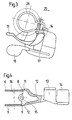
- a switch 3 is by means of a clamp 26 attached to the handlebar, the housing 3 substantially below the Handlebar 1 is arranged.
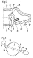
- a central axis 16 is arranged in the interior of the housing 3, around which an actuating part 4 can rotate, on which a winding groove 5 for a traction rope is attached, which is connected to a bicycle transmission and in the Housing 3 can enter via an opening 23.
- a first locking disk 6 is arranged with a first locking tooth segment 8
- a second locking disk 7 is arranged with a second locking tooth segment 9 and a toothing 24.
- An actuating lever 17 is also rotatably arranged about the central axis 16 a handle part 18, wherein a pawl 19 is rotatably arranged on the operating lever 17 and is sprung against the toothing 24.
- a release lever 10 is pivotably arranged in an axis of rotation 15 fixed to the housing and has a first locking lug 11 at its end facing the actuating part 4 and a second locking lug 12, the first locking lug 11 with the first locking tooth segment 8 and the second locking lug 12 cooperate with the second locking tooth segment 9.
- the axis of rotation 15 is arranged essentially perpendicular to the central axis 16, the distance of the axis of rotation 15 from the central axis 16 is approximately that Radius of the locking tooth segments 8 and 9 corresponds.
- the position of the axis of rotation 15 by an essentially equal distance from the first locking tooth segment 8 and defined by the second locking tooth segment 9.
- the release lever 10 is through one here Biased spring not shown in such a way that the second locking lug 12th comes into engagement with the second locking tooth segment 9. In this position the Release lever 10 on a stop of the housing 3.
- the far end of the release lever 10 opens into a first handle button 13 and a second handle button 14, the first handle button 13 according to FIG. 3 in one direction of travel 25 seen the handlebar 1 lagging and the second handle button 14 in the direction of travel 25 are arranged in advance.
- the release lever 10 In the rest position of the release lever 10 can be the handle buttons 13 and 14 together up to the stop at the maximum Move the grip part 2 of the handlebar 1, the second locking lug 12 of the release lever 10 comes out of engagement with the second locking tooth segment 9, while the first locking lug 11 of the release lever 10 comes into engagement with the first locking tooth segment 8.
- the pawl 19 is not in engagement with the toothing 24, the actuating part 4 is turned back by the return spring in the bicycle transmission, so that the engaged second locking lug 12 in the second locking tooth segment 9 the Reverse rotation of the actuating part 4 and thus prevents the pull rope from running out.
- the release lever 10 by touching one of the handle buttons 13 or 14 the second locking lug 12 is brought out of engagement with the second locking tooth segment 9, while the first locking lug 11 is already in engagement with the first locking tooth segment 8 has come at least partially, whereby the operating part 4 by about half a gear has been turned.
- the ratchet tooth segments 8 and 9 are through the pointed shape of their teeth matched so that the alternate engagement the first locking lug 11 into the first locking tooth segment 8 without lost motion with the engagement the second locking lug 12 can take place in the second locking tooth segment 9, whereby when the release lever 10 is released by releasing the first handle button 13 or the second handle button 14 causes the downshift from a first to a second gear becomes.
- the advantage of the invention lies in the simple actuation of the actuation lever 17 and the release lever 10 or 10 ', with the ergonomics of the lever design was taken into account and being the bicycle transmission under all circumstances is switchable, even if the driver's operating hand is moved by other movements, for example by actuating a brake lever.
Landscapes
- Engineering & Computer Science (AREA)
- Mechanical Engineering (AREA)
- Chemical & Material Sciences (AREA)
- Combustion & Propulsion (AREA)
- Transportation (AREA)
- Steering Devices For Bicycles And Motorcycles (AREA)
- Mechanical Control Devices (AREA)
Applications Claiming Priority (3)
| Application Number | Priority Date | Filing Date | Title |
|---|---|---|---|
| DE19809113 | 1998-03-04 | ||
| DE19809113A DE19809113A1 (de) | 1998-03-04 | 1998-03-04 | Schalter für Fahrradgetriebe |
| EP99101830A EP0940334B1 (fr) | 1998-03-04 | 1999-01-28 | Dispositif de commande pour dérailleur de bicyclette |
Related Parent Applications (1)
| Application Number | Title | Priority Date | Filing Date |
|---|---|---|---|
| EP99101830A Division EP0940334B1 (fr) | 1998-03-04 | 1999-01-28 | Dispositif de commande pour dérailleur de bicyclette |
Publications (3)
| Publication Number | Publication Date |
|---|---|
| EP1445187A2 true EP1445187A2 (fr) | 2004-08-11 |
| EP1445187A3 EP1445187A3 (fr) | 2007-09-05 |
| EP1445187B1 EP1445187B1 (fr) | 2009-03-11 |
Family
ID=7859603
Family Applications (2)
| Application Number | Title | Priority Date | Filing Date |
|---|---|---|---|
| EP99101830A Expired - Lifetime EP0940334B1 (fr) | 1998-03-04 | 1999-01-28 | Dispositif de commande pour dérailleur de bicyclette |
| EP04010917A Expired - Lifetime EP1445187B1 (fr) | 1998-03-04 | 1999-01-28 | Dispositif de commande pour dérailleur de bicyclette |
Family Applications Before (1)
| Application Number | Title | Priority Date | Filing Date |
|---|---|---|---|
| EP99101830A Expired - Lifetime EP0940334B1 (fr) | 1998-03-04 | 1999-01-28 | Dispositif de commande pour dérailleur de bicyclette |
Country Status (3)
| Country | Link |
|---|---|
| US (1) | US6095010A (fr) |
| EP (2) | EP0940334B1 (fr) |
| DE (3) | DE19809113A1 (fr) |
Families Citing this family (28)
| Publication number | Priority date | Publication date | Assignee | Title |
|---|---|---|---|---|
| DE19915336A1 (de) | 1999-04-03 | 2000-10-05 | Sram De Gmbh | Schalter für ein Fahrradgetriebe |
| US6862948B1 (en) | 2001-10-18 | 2005-03-08 | John L. Calendrille, Jr. | Shifter for a bicycle using a dual action lever which moves in the same motion as the natural movement of the thumb |
| ITTO20011079A1 (it) * | 2001-11-16 | 2003-05-16 | Campagnolo Srl | ,,dispositivo di comando del cambio per una bicicletta avente un manubrio con estremita' diritte,, |
| US20030230160A1 (en) * | 2002-03-20 | 2003-12-18 | Ritchey Designs, Inc. | Barend mounted twist shifter with integrated brake actuator for bicycle |
| DE10213450B4 (de) * | 2002-03-26 | 2020-02-13 | Sram Deutschland Gmbh | Freigabeeinrichtung für Triggerschalter |
| DE10224196A1 (de) * | 2002-05-31 | 2003-12-11 | Sram De Gmbh | Seileinzugmechanik für Triggerschalter |
| US8069749B2 (en) * | 2002-07-05 | 2011-12-06 | Shimano, Inc. | Shift control device for a bicycle transmission |
| US7194928B2 (en) * | 2003-05-30 | 2007-03-27 | Shimano Inc. | Bicycle shift operating device |
| US7228756B2 (en) * | 2003-11-25 | 2007-06-12 | Shimano Inc. | Bicycle control device |
| EP1564131B1 (fr) * | 2004-02-06 | 2007-08-15 | Campagnolo S.R.L. | Dispositif d'actionnement pour un câble de commande de changement de vitesse pour bicyclette |
| DE102004014035A1 (de) * | 2004-03-19 | 2005-10-06 | Sram Deutschland Gmbh | Fahrrad-Gangschaltungseinrichtung |
| US7437969B2 (en) * | 2004-09-29 | 2008-10-21 | Shimano Inc. | Bicycle shift operating device |
| US8549954B2 (en) | 2004-09-30 | 2013-10-08 | Shimano, Inc. | Bicycle shift device having a linearly sliding shift lever operated by a pivoting interface member |
| EP2042420B1 (fr) * | 2005-06-27 | 2011-08-17 | CAMPAGNOLO S.r.l. | Dispositif de commande pour dérailleur de bicyclette |
| JP5027999B2 (ja) * | 2005-07-08 | 2012-09-19 | キヤノン株式会社 | 記録装置およびその制御方法 |
| DE602006016343D1 (de) * | 2006-01-23 | 2010-09-30 | Campagnolo Srl | Steuervorrichtung für fahrradkettenschaltung |
| EP1826111B1 (fr) * | 2006-02-23 | 2010-06-30 | CAMPAGNOLO S.r.l. | Appareil de contrôle de frein de bicyclette |
| ITMI20070239A1 (it) * | 2007-02-09 | 2008-08-10 | Campagnolo Srl | Dispositivo di comando per un deragliatore di bicicletta |
| ITMI20070400A1 (it) * | 2007-03-01 | 2008-09-02 | Campagnolo Srl | Dispositivo di comando per bicicletta e bicicletta comprendente tale dipsositivo |
| ITMI20072230A1 (it) * | 2007-11-23 | 2009-05-24 | Campagnolo Srl | Dispositivo di comando per bicicletta con manubrio ricurvo |
| US10017224B2 (en) * | 2008-01-08 | 2018-07-10 | Shimano Inc. | Bicycle shift operating device |
| US9227689B2 (en) | 2008-01-08 | 2016-01-05 | Shimano Inc. | Bicycle shift operating device |
| CN102530186B (zh) * | 2010-12-21 | 2013-11-06 | 天心工业股份有限公司 | 自行车变速把手 |
| CN102849172A (zh) * | 2011-06-30 | 2013-01-02 | 久鼎金属实业股份有限公司 | 电动自行车的变速机构 |
| US10239581B2 (en) | 2011-08-26 | 2019-03-26 | Gevenalle, Inc | Bicycle brake and shift lever assembly |
| US9836076B2 (en) * | 2013-01-31 | 2017-12-05 | Shimano Inc. | Bicycle operating device |
| CN106995035B (zh) * | 2017-04-17 | 2022-05-03 | 珠海蓝图控制器科技有限公司 | 一种自行车换挡器 |
| CN106904246B (zh) * | 2017-04-17 | 2022-05-03 | 珠海蓝图控制器科技有限公司 | 一种自行车换挡器 |
Citations (1)
| Publication number | Priority date | Publication date | Assignee | Title |
|---|---|---|---|---|
| EP0352733B1 (fr) | 1988-07-29 | 1994-08-17 | Shimano Inc. | Levier de commande de changement de vitesse pour une bicyclette |
Family Cites Families (8)
| Publication number | Priority date | Publication date | Assignee | Title |
|---|---|---|---|---|
| US5222412A (en) * | 1988-07-29 | 1993-06-29 | Shimano Industrial Co., Ltd. | Change speed lever apparatus for use in bicycle |
| US5012692A (en) * | 1988-09-24 | 1991-05-07 | Shimano Industrial Company Limited | Change-speed lever apparatus for use in bicycle |
| JP2523752Y2 (ja) * | 1990-03-26 | 1997-01-29 | マエダ工業株式会社 | 自転車用変速操作レバー装置 |
| EP0472739B1 (fr) * | 1990-03-09 | 1996-01-31 | Mory Suntour Inc. | Dispositif de levier de commande de changement de vitesse pour bicyclette |
| JP2601207Y2 (ja) * | 1992-12-28 | 1999-11-15 | 株式会社シマノ | 自転車用の変速操作装置 |
| TW211548B (en) * | 1993-03-09 | 1993-08-21 | Shimano Kk | Speed changing device of a bicycle |
| JP3644604B2 (ja) * | 1994-03-07 | 2005-05-11 | 株式会社シマノ | 自転車用変速操作装置 |
| US5682794A (en) * | 1996-06-05 | 1997-11-04 | Shimano, Inc. | Bicycle shifting control unit |
-
1998
- 1998-03-04 DE DE19809113A patent/DE19809113A1/de not_active Withdrawn
-
1999
- 1999-01-28 EP EP99101830A patent/EP0940334B1/fr not_active Expired - Lifetime
- 1999-01-28 EP EP04010917A patent/EP1445187B1/fr not_active Expired - Lifetime
- 1999-01-28 DE DE59909926T patent/DE59909926D1/de not_active Expired - Lifetime
- 1999-01-28 DE DE59914980T patent/DE59914980D1/de not_active Expired - Lifetime
- 1999-03-04 US US09/262,544 patent/US6095010A/en not_active Expired - Fee Related
Patent Citations (1)
| Publication number | Priority date | Publication date | Assignee | Title |
|---|---|---|---|---|
| EP0352733B1 (fr) | 1988-07-29 | 1994-08-17 | Shimano Inc. | Levier de commande de changement de vitesse pour une bicyclette |
Also Published As
| Publication number | Publication date |
|---|---|
| EP1445187B1 (fr) | 2009-03-11 |
| DE19809113A1 (de) | 1999-09-09 |
| EP1445187A3 (fr) | 2007-09-05 |
| EP0940334B1 (fr) | 2004-07-14 |
| DE59914980D1 (de) | 2009-04-23 |
| US6095010A (en) | 2000-08-01 |
| DE59909926D1 (de) | 2004-08-19 |
| EP0940334A1 (fr) | 1999-09-08 |
Similar Documents
| Publication | Publication Date | Title |
|---|---|---|
| EP0940334B1 (fr) | Dispositif de commande pour dérailleur de bicyclette | |
| EP1935777B2 (fr) | Commutateur pour un engrenage de vélo | |
| DE69203639T2 (de) | Geschwindigkeitssteuergerät für ein Fahrrad. | |
| DE69702149T2 (de) | Hebelverlängerung für eine Fahrradgangschaltung | |
| DE69004614T2 (de) | Gangschaltung für ein Fahrrad. | |
| DE68928570T2 (de) | Fahrrad-Steuerungsvorrichtung | |
| DE69700390T2 (de) | Fahrrad-Gangschaltungshebel | |
| DE68913113T2 (de) | Gangschaltungshebel für ein Fahrrad. | |
| DE69502644T2 (de) | Gangschaltapparat für ein Fahrrad | |
| DE69116516T2 (de) | Fahrradgeschwindigkeitssteuergerät | |
| DE3404797C2 (fr) | ||
| DE69130806T2 (de) | Fahrrad-Geschwindigkeitssteuergerät mit Steuerdraht | |
| DE60117226T2 (de) | Steuerungseinrichtung für eine Fahrradgangschaltung | |
| DE69509175T2 (de) | Fahrrad-Gangschaltungs-Einrichtung | |
| DE102004014035A1 (de) | Fahrrad-Gangschaltungseinrichtung | |
| EP0694450B1 (fr) | Dispositif pour verrouiller la clef de contact d'un véhicule automobile au moyen du levier de sélection de la boíte de vitesse automatique | |
| DE19753901A1 (de) | Schalter für ein Fahrradgetriebe | |
| DE3823385C2 (fr) | ||
| DE10007592A1 (de) | Schalter zur Betätigung eines Getriebes an einem Fahrrad | |
| DE4409251C1 (de) | Schaltbetätigungseinrichtung für Wechselgetriebe an Fahrrädern | |
| DE19609723A1 (de) | Betätigungsvorrichtung für Fahrradgangschaltungen | |
| EP2244933A1 (fr) | Dispositif de changement de vitesse | |
| DE3440066C2 (fr) | ||
| DE3440071A1 (de) | Mehrgangnabe fuer fahrraeder oder dergleichen, mit gangumschaltung fuer mehr als drei gaenge | |
| WO1995003208A1 (fr) | Derailleur de bicyclette |
Legal Events
| Date | Code | Title | Description |
|---|---|---|---|
| PUAI | Public reference made under article 153(3) epc to a published international application that has entered the european phase |
Free format text: ORIGINAL CODE: 0009012 |
|
| 17P | Request for examination filed |
Effective date: 20040507 |
|
| AC | Divisional application: reference to earlier application |
Ref document number: 0940334 Country of ref document: EP Kind code of ref document: P |
|
| AK | Designated contracting states |
Kind code of ref document: A2 Designated state(s): DE FR GB SE |
|
| PUAL | Search report despatched |
Free format text: ORIGINAL CODE: 0009013 |
|
| AK | Designated contracting states |
Kind code of ref document: A3 Designated state(s): DE FR GB SE |
|
| AKX | Designation fees paid |
Designated state(s): DE FR |
|
| 17Q | First examination report despatched |
Effective date: 20080711 |
|
| GRAP | Despatch of communication of intention to grant a patent |
Free format text: ORIGINAL CODE: EPIDOSNIGR1 |
|
| GRAS | Grant fee paid |
Free format text: ORIGINAL CODE: EPIDOSNIGR3 |
|
| GRAA | (expected) grant |
Free format text: ORIGINAL CODE: 0009210 |
|
| 111Z | Information provided on other rights and legal means of execution |
Free format text: DE FR Effective date: 20090106 |
|
| AC | Divisional application: reference to earlier application |
Ref document number: 0940334 Country of ref document: EP Kind code of ref document: P |
|
| AK | Designated contracting states |
Kind code of ref document: B1 Designated state(s): DE FR |
|
| REF | Corresponds to: |
Ref document number: 59914980 Country of ref document: DE Date of ref document: 20090423 Kind code of ref document: P |
|
| PLBE | No opposition filed within time limit |
Free format text: ORIGINAL CODE: 0009261 |
|
| STAA | Information on the status of an ep patent application or granted ep patent |
Free format text: STATUS: NO OPPOSITION FILED WITHIN TIME LIMIT |
|
| 26N | No opposition filed |
Effective date: 20091214 |
|
| PGFP | Annual fee paid to national office [announced via postgrant information from national office to epo] |
Ref country code: DE Payment date: 20130117 Year of fee payment: 15 |
|
| PGFP | Annual fee paid to national office [announced via postgrant information from national office to epo] |
Ref country code: FR Payment date: 20140123 Year of fee payment: 16 |
|
| REG | Reference to a national code |
Ref country code: DE Ref legal event code: R119 Ref document number: 59914980 Country of ref document: DE |
|
| REG | Reference to a national code |
Ref country code: DE Ref legal event code: R119 Ref document number: 59914980 Country of ref document: DE Effective date: 20140801 |
|
| PG25 | Lapsed in a contracting state [announced via postgrant information from national office to epo] |
Ref country code: DE Free format text: LAPSE BECAUSE OF NON-PAYMENT OF DUE FEES Effective date: 20140801 |
|
| REG | Reference to a national code |
Ref country code: FR Ref legal event code: ST Effective date: 20150930 |
|
| PG25 | Lapsed in a contracting state [announced via postgrant information from national office to epo] |
Ref country code: FR Free format text: LAPSE BECAUSE OF NON-PAYMENT OF DUE FEES Effective date: 20150202 |