EP1445524A2 - Beheizbarer Kugelhahn und damit ausgestattete Rohrleitung - Google Patents
Beheizbarer Kugelhahn und damit ausgestattete Rohrleitung Download PDFInfo
- Publication number
- EP1445524A2 EP1445524A2 EP04000379A EP04000379A EP1445524A2 EP 1445524 A2 EP1445524 A2 EP 1445524A2 EP 04000379 A EP04000379 A EP 04000379A EP 04000379 A EP04000379 A EP 04000379A EP 1445524 A2 EP1445524 A2 EP 1445524A2
- Authority
- EP
- European Patent Office
- Prior art keywords
- ball valve
- inlet
- outlet
- heating
- ball
- Prior art date
- Legal status (The legal status is an assumption and is not a legal conclusion. Google has not performed a legal analysis and makes no representation as to the accuracy of the status listed.)
- Granted
Links
- 238000010438 heat treatment Methods 0.000 claims description 65
- 239000012530 fluid Substances 0.000 claims description 4
- 239000002826 coolant Substances 0.000 claims description 2
- 239000000126 substance Substances 0.000 abstract description 3
- 238000012546 transfer Methods 0.000 description 13
- 238000007789 sealing Methods 0.000 description 8
- 238000003466 welding Methods 0.000 description 6
- 238000001816 cooling Methods 0.000 description 5
- 239000007788 liquid Substances 0.000 description 3
- 238000004519 manufacturing process Methods 0.000 description 3
- 238000007711 solidification Methods 0.000 description 2
- 230000008023 solidification Effects 0.000 description 2
- 206010053615 Thermal burn Diseases 0.000 description 1
- 229940053200 antiepileptics fatty acid derivative Drugs 0.000 description 1
- 239000003795 chemical substances by application Substances 0.000 description 1
- 235000014113 dietary fatty acids Nutrition 0.000 description 1
- 238000002474 experimental method Methods 0.000 description 1
- 229930195729 fatty acid Natural products 0.000 description 1
- 239000000194 fatty acid Substances 0.000 description 1
- 150000004665 fatty acids Chemical class 0.000 description 1
- 238000009434 installation Methods 0.000 description 1
- 238000009413 insulation Methods 0.000 description 1
- 230000010354 integration Effects 0.000 description 1
- 238000005259 measurement Methods 0.000 description 1
- 238000000691 measurement method Methods 0.000 description 1
- 238000000034 method Methods 0.000 description 1
- 229910001220 stainless steel Inorganic materials 0.000 description 1
- 239000010935 stainless steel Substances 0.000 description 1
- 230000007704 transition Effects 0.000 description 1
- XLYOFNOQVPJJNP-UHFFFAOYSA-N water Substances O XLYOFNOQVPJJNP-UHFFFAOYSA-N 0.000 description 1
Images


Classifications
-
- F—MECHANICAL ENGINEERING; LIGHTING; HEATING; WEAPONS; BLASTING
- F16—ENGINEERING ELEMENTS AND UNITS; GENERAL MEASURES FOR PRODUCING AND MAINTAINING EFFECTIVE FUNCTIONING OF MACHINES OR INSTALLATIONS; THERMAL INSULATION IN GENERAL
- F16K—VALVES; TAPS; COCKS; ACTUATING-FLOATS; DEVICES FOR VENTING OR AERATING
- F16K49/00—Means in or on valves for heating or cooling
- F16K49/005—Circulation means for a separate heat transfer fluid
-
- F—MECHANICAL ENGINEERING; LIGHTING; HEATING; WEAPONS; BLASTING
- F16—ENGINEERING ELEMENTS AND UNITS; GENERAL MEASURES FOR PRODUCING AND MAINTAINING EFFECTIVE FUNCTIONING OF MACHINES OR INSTALLATIONS; THERMAL INSULATION IN GENERAL
- F16K—VALVES; TAPS; COCKS; ACTUATING-FLOATS; DEVICES FOR VENTING OR AERATING
- F16K27/00—Construction of housing; Use of materials therefor
- F16K27/06—Construction of housing; Use of materials therefor of taps or cocks
- F16K27/067—Construction of housing; Use of materials therefor of taps or cocks with spherical plugs
Definitions
- the invention relates to a heatable or coolable ball valve with a Inlet connection and an outlet connection for the flowing fluid.
- the Middle part carrying the locking ball with the housing at the inlet and at the outlet each has a flange, the housing between the screws connected flanges, the inlet connection and the Outlet connection from the respective flange to the outside.
- the two nozzles namely the Inlet connector and outlet connector also from the housing itself to the outside protrude.
- These sockets are for connecting to the pipes for the fluid, namely a gas or a liquid, and can be provided with these pipes welded or screwed.
- heated fittings and in particular also heated ball valves have been developed, which however do not completely satisfy the demands made can.
- heated ball valves can be found in German Utility model DE 94 07 069 U1 (Hoechst AG) and in the Austrian Patent specification AT 386 470 B (IPARI SZERELVENY ES GEPGYAR).
- it is Central part carrying the locking ball, i.e. the housing, from a separate one Surround heating jacket, which with its inlets and outlets to a heat transfer circuit is to be connected.
- a heatable slide is known from DE 28 32 505 U1 (Schnell). To do that The slide housing is welded to a jacket. Through the educated Mantle space can flow a heating medium such as steam.
- a ball valve is compared to the usually relatively large slides however usually too small for such a thermal jacket. An exchange of the Valve ball would not be possible without draining the heating medium.
- the for Feeding the heating medium into the jacket space of the known slide required channels in the flanges also lead to a high Pressure loss for the entire heating jacket.
- the channels in the flange require corresponding corresponding holes in the flange seal. Because of these Holes must be a common occurrence in practice when installing the slide Moving the seal should be avoided under all circumstances.
- shut-off element in the manner of a slide for Hot gas pipeline (U.S. 3,430,689, Pantke et al.). Here only the Inlet and outlet flanges cooled. The overall arrangement is significant more cumbersome and complex than that described below Heating a ball valve according to the invention.
- the invention is therefore based on the object of the disadvantages mentioned avoid and especially with a ball valve of the type mentioned to solve the following subtasks at the same time.
- Better heating the critical points of the ball valve should be reached in order to block the Pipelines with high security due to cold bridges in the ball valve prevent.
- the sealing washers and the sealing ball i.e. the sealing body, should be able to be exchanged without problems, without the heating medium would have to be drained for heating or cooling the ball valve.
- the Cost of manufacturing the ball valve heater is said to be significant are lower than in the prior art.
- the installation of the ball valve should be easier and faster. After all, there shouldn't be any additional heating medium only for heating or cooling the ball valve to be required.
- Both the inlet connection and the outlet connection are preferably from surrounded such an outer socket, which with the heating jacket pipeline to be connected can be connected.
- the existing one anyway In this way, heating medium for the pipeline becomes very close and immediate to the outside of the flanges of the ball valve or the housing of the ball valve so that the ball valve opens quickly and effectively heated to about the same temperature as the heating jacket of the pipeline is and remains heated.
- Replacing the sealing washers and Locking ball can be used in the same way as for an unheated ball valve, So without draining the heat medium for the ball valve and without one Pull apart the subsequent pipes.
- the ball valve according to the invention can be heated to any high temperature be, the temperature limit depending on the temperature resistance the seals aligns. In a corresponding manner, the ball valve can also be cooled to any low temperature. All common heating media or cooling media can be used.
- the ball valve according to the invention is particularly simple and easy to use Connect the pipeline when the inlet nozzle or the outlet nozzle protrudes further outwards than the outer connector. First, namely Usually the inlet nozzle or outlet nozzle is welded on or screwed on. Only then is the outer connector on the ball valve connected, also by welding or screwing.
- the ball valve in a manner known per se the ball has surrounding housing, which on the inlet and on the outlet side is releasably connected to flanges, in particular by means of screws, and if the inlet connection and the outlet connection as well as the outer connection of the respective Project the flange outwards. To remove the middle section with the Then only the screws are loosened and the housing is pulled out. It is included in a trapezoidal shape of the flanges, which is also known per se only required to loosen the screws without removing them.
- valve ball is particularly easy to do without draining the heating medium change if, according to a further embodiment of the invention, the annular space ends in the area of the flange.
- the invention further relates to a heatable, provided with a heating jacket Pipeline with a ball valve of the type according to the invention.
- a heatable provided with a heating jacket Pipeline with a ball valve of the type according to the invention.
- the annulus immediately passes into the heating jacket, so that no pressure loss occurs during this transition.
- the heating jacket on the inlet side and the outlet-side heating jacket of the pipeline via an additional line are interconnected.
- the connections of the additional line are included preferably arranged in the area of the outer socket of the ball valve.
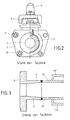
- the ball valve known from the prior art according to FIGS. 1 and 2 has a housing 1 in which the locking ball 2 is rotatable about the axis 3 is arranged.
- the ball 2 can by means of the hand lever 4 and the pin 5 in the closing and opening positions are rotated.
- At the inlet and outlet are also a flange 6 with an outwardly projecting inlet connection 7 and a flange 8 by means of an outlet nozzle 9 also projecting outwards Bolt 10 screwed together so that the inner Sealing surfaces of the flanges 6, 8 sealing against the corresponding surfaces of the Housing 1 are pressed.
- the housing seal 11 and the ball seat 12 to recognize which are replaced from time to time have to.
- the nuts 13 are loosened, so that the housing 1 pulled out of the space between flanges 6 and 8 above can. Then the seals can be changed and the housing with the Lock ball to be reinstalled in a corresponding manner.
- connection of the ball valve with a known from the prior art heated pipe is schematically in longitudinal section in Figure 3, for example on Outlet connector 9 of the flange 8, shown.
- the pipe 15 is on the End face welded to the corresponding end face of the outlet connector 9. Instead of this butt welding, a plug-in welding or a Screwing be provided by means of a corresponding thread.
- the Heating jacket 16b of the pipeline 15 is also indicated in FIG. 3.
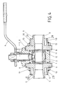
- the ball valve according to the invention is shown in one embodiment in FIG Longitudinal section shown. It is essential to the invention that the inlet connection 7 of an outer socket 17 and the outlet socket 9 from an outer socket 18 is surrounded, these outer sockets 17, 18 for connecting the heating jacket the pipeline are provided and suitable.
- a corresponding connection of the Pipeline 15 to the outlet nozzle 9 and the connection of the heating jacket 16b on the outer socket 18 of the flange 8 are schematically in section in Figure 5 shown. The connections were made here by butt welding performed.
- FIG 6 shows a perspective view of another invention Ball valve, the inlet port 7 facing the viewer.
- Ball valve according to Figure 4 are the inlet flange 6, the inlet port 7 and the Outer socket 17 made in one piece. The same applies to the Outlet flange 8.
- the pipeline is first 15 for the product on the inner inlet port 7 or on the inner outlet nozzle 9 connected by welding. Then the Heating jackets 16a, 16b welded to the respective outer connector 17, 18.
- the heating medium reaches up to the outside of the flanges 6, 8 and thus directly to the critical points of the ball valve where in the prior art cold bridges and thus problems due to solidification of the Product occur.
- the problems existing in the prior art the occur especially when starting up a system and not despite preheating can be eliminated, no longer occur in the solution according to the invention on.
- the lengths of the inlet spigot, the outlet spigot and the outer spigot can be different according to the invention, with greater lengths of these Neck are preferred.
- the housing 1 and the flanges 6, 8 are preferably made of stainless steel.
- the Ball valve according to the invention can be used not only with increased and also high Temperature of the product flowing through, but also for products that are pressed through pipelines under high pressure.
- the main advantages of the invention Ball valve on the one hand in a better and faster integration of the ball valve in a double jacket line.
- the assembly of the ball valve and the Pipe parts are simplified considerably. Better heating at the critical points of the ball valve with a very good heat transfer reached. Because the heating medium when changing the sealing set of the ball valve does not have to be emptied, the previous risk of accidents arises Scalds no more. An otherwise complex production of Aids for heating the ball valve are not required.
Landscapes
- Engineering & Computer Science (AREA)
- General Engineering & Computer Science (AREA)
- Mechanical Engineering (AREA)
- Physics & Mathematics (AREA)
- Thermal Sciences (AREA)
- Multiple-Way Valves (AREA)
- Taps Or Cocks (AREA)
- Valve Housings (AREA)
- Details Of Valves (AREA)
- Joints Allowing Movement (AREA)
Abstract
Description
- Figur 1
- einen Kugelhahn nach dem Stand der Technik, teilweise in einer Seitenansicht und teilweise im Schnitt,
- Figur 2
- den Kugelhahn nach dem Stand der Technik nach Figur 1 in einer Ansicht in Richtung des Pfeiles 14 in Figur 1 auf den Einlass, also von vorn, ebenfalls teilweise von außen und teilweise im Schnitt,
- Figur 3
- den Flansch eines aus dem Stand der Technik bekannten Kugelhahns mit angeschlossener Rohrleitung,
- Figur 4
- einen Kugelhahn nach dem erfindungsgemäßen Ausführungsbeispiel im Schnitt,
- Figur 5
- eine Variante des Flansches des erfindungsgemäßen Kugelhahnes nach Figur 4, im Längsschnitt mit angeschlossener Rohrleitung,
- Figur 6
- eine perspektivische Ansicht eines erfindungsgemäßen Kugelhahns nach einem weiteren Ausführungsbeispiel und
- Figur 7
- eine perspektivische Ansicht einer Rohrleitung mit einem eingebauten erfindungsgemäßen Kugelhahn.
- 1
- Gehäuse
- 2
- Verschlusskugel
- 3
- Achse
- 4
- Handhebel
- 5
- Bolzen
- 6
- Flansch
- 7
- Einlassstutzen
- 8
- Flansch
- 9
- Auslassstutzen
- 10
- Schraubenbolzen
- 11
- Gehäusedichtung
- 12
- Kugelsitz
- 13
- Mutter
- 14
- Pfeil
- 15
- Rohrleitung
- 16a
- einlassseitiger Heizmantel
- 16b
- auslassseitiger Heizmantel
- 17
- Außenstutzen
- 18
- Außenstutzen
- 19
- Zusatzleitung
- 20
- Schweißnaht
- 21
- Schweißnaht
- 22
- Pfeil
- 23
- Ringraum
- 24
- Ringraum
Claims (8)
- Beheizbarer oder kühlbarer Kugelhahn mit einem Einlassstutzen (7) und einem Auslassstutzen (9) für das durchströmende Fluid,
dadurch gekennzeichnet, dass mindestens einer der Stutzen (7; 9) von einem Außenstutzen (17; 18) umgeben ist. - Kugelhahn nach Anspruch 1,
dadurch gekennzeichnet, dass der mindestens eine Stutzen (7; 9) und der umgebende Außenstutzen (17; 18) einen einseitig geschlossenen Ringraum (23; 24) für das Heizoder Kühlmedium bilden. - Kugelhahn nach Anspruch 1 oder 2,
dadurch gekennzeichnet, dass der Einlassstutzen (7) bzw. der Auslassstutzen (9) weiter nach außen ragt als der Außenstutzen (17; 18). - Kugelhahn nach einem der vorhergehenden Ansprüche,
dadurch gekennzeichnet, dass der Kugelhahn ein die Verschlusskugel (2) umgebendes Gehäuse (1) aufweist, welches an der Einlass- und an der Auslassseite mit Flanschen (6; 8), insbesondere mittels Schraubenbolzen (10), lösbar verbunden ist, und dass der Einlassstutzen (7) und der Auslassstutzen (9) sowie die Außenstutzen (17; 18) von dem jeweiligen Flansch (6; 8) nach außen ragen. - Kugelhahn nach dem vorhergehenden Anspruch,
dadurch gekennzeichnet, dass der Ringraum (23; 24) im Bereich des Flansches (6; 8) endet. - Beheizbare, mit einem Heizmantel (16a) versehene Rohrleitung (15) mit einem Kugelhahn nach einem der vorhergehenden Ansprüche,
dadurch gekennzeichnet, dass der Ringraum (23; 24) unmittelbar in den Heizmantel (16a) übergeht. - Rohrleitung nach dem vorhergehenden Anspruch,
dadurch gekennzeichnet, dass der einlassseitige Heizmantel (16a) und der auslassseitige Heizmantel (16b) der Rohrleitung (15) über eine Zusatzleitung (19) miteinander verbunden sind. - Rohrleitung nach Anspruch 7,
dadurch gekennzeichnet, dass die Anschlüsse der Zusatzleitung (19) im Bereich der Außenstutzen (17; 18) des Kugelhahns angeordnet sind.
Applications Claiming Priority (2)
| Application Number | Priority Date | Filing Date | Title |
|---|---|---|---|
| DE20301744U DE20301744U1 (de) | 2003-02-04 | 2003-02-04 | Beheizbarer Kugelhahn und damit ausgestattete Rohrleitung |
| DE20301744U | 2003-02-04 |
Publications (3)
| Publication Number | Publication Date |
|---|---|
| EP1445524A2 true EP1445524A2 (de) | 2004-08-11 |
| EP1445524A3 EP1445524A3 (de) | 2004-11-10 |
| EP1445524B1 EP1445524B1 (de) | 2006-08-02 |
Family
ID=32520282
Family Applications (1)
| Application Number | Title | Priority Date | Filing Date |
|---|---|---|---|
| EP04000379A Expired - Lifetime EP1445524B1 (de) | 2003-02-04 | 2004-01-10 | Beheizbarer Kugelhahn und damit ausgestattete Rohrleitung |
Country Status (3)
| Country | Link |
|---|---|
| EP (1) | EP1445524B1 (de) |
| DE (2) | DE20301744U1 (de) |
| ES (1) | ES2268502T3 (de) |
Citations (5)
| Publication number | Priority date | Publication date | Assignee | Title |
|---|---|---|---|---|
| US3430689A (en) | 1966-09-27 | 1969-03-04 | Huettenwerk Oberhausen Ag | Fluid-control member |
| DE2832505A1 (de) | 1978-07-25 | 1980-02-07 | Schnell Geb Ehrich Rosemarie | Armatur fuer rohrleitungsanlagen, insbesondere ventil, schieber o.dgl. |
| AT386470B (de) | 1982-07-28 | 1988-08-25 | Ipari Szerelveny & Gepgyar | Kugelhahn mit heizmantel |
| DE9407069U1 (de) | 1994-04-28 | 1994-06-09 | Hoechst Ag, 65929 Frankfurt | Kugelhahn für Hochtemperaturbetrieb |
| DE9414156U1 (de) | 1994-09-01 | 1994-11-24 | Ksb Aktiengesellschaft, 67227 Frankenthal | Ummanteltes Kugelhahngehäuse |
Family Cites Families (10)
| Publication number | Priority date | Publication date | Assignee | Title |
|---|---|---|---|---|
| DE568597C (de) * | 1932-07-16 | 1933-01-21 | Lignose Ag | Mit Beheizung bzw. Kuehlung versehener Absperrhahn |
| GB565902A (en) * | 1943-06-11 | 1944-12-04 | Callenders Cable & Const Co | An improved construction of stop valve |
| US3038489A (en) * | 1960-04-06 | 1962-06-12 | Cameron Iron Works Inc | Valves |
| US3894718A (en) * | 1973-10-19 | 1975-07-15 | Whitey Research Tool Co | Ball valve |
| DE2633809C2 (de) * | 1976-07-28 | 1983-07-14 | Klein, Schanzlin & Becker Ag, 6710 Frankenthal | Hochtemperatur-Armatur |
| DE3147295A1 (de) * | 1981-11-28 | 1983-06-09 | Wolfgang Dr.-Ing. 6700 Ludwigshafen Kost | Element zum einbau von armaturen, messgeraeten od.dgl. in beheizte oder gekuehlte rohrleitungen |
| DE3436994C1 (de) * | 1984-09-11 | 1986-02-06 | Wilhelm 4150 Krefeld Schulz | Flansch |
| US4583570A (en) * | 1984-10-15 | 1986-04-22 | Foster Wheeler Energy Corporation | Liquid cooled ball valve |
| DE3518206A1 (de) * | 1985-05-21 | 1986-11-27 | Bruno Dipl.-Ing. 6000 Frankfurt Behrens | Waermebeeinflussbares kugelventil |
| DE8709109U1 (de) * | 1987-07-01 | 1987-11-05 | Chemat GmbH Armaturen für Industrie- und Nuklearanlagen, 7592 Renchen | Heizmantel |
-
2003
- 2003-02-04 DE DE20301744U patent/DE20301744U1/de not_active Expired - Lifetime
-
2004
- 2004-01-10 ES ES04000379T patent/ES2268502T3/es not_active Expired - Lifetime
- 2004-01-10 DE DE200450001059 patent/DE502004001059D1/de not_active Expired - Lifetime
- 2004-01-10 EP EP04000379A patent/EP1445524B1/de not_active Expired - Lifetime
Patent Citations (5)
| Publication number | Priority date | Publication date | Assignee | Title |
|---|---|---|---|---|
| US3430689A (en) | 1966-09-27 | 1969-03-04 | Huettenwerk Oberhausen Ag | Fluid-control member |
| DE2832505A1 (de) | 1978-07-25 | 1980-02-07 | Schnell Geb Ehrich Rosemarie | Armatur fuer rohrleitungsanlagen, insbesondere ventil, schieber o.dgl. |
| AT386470B (de) | 1982-07-28 | 1988-08-25 | Ipari Szerelveny & Gepgyar | Kugelhahn mit heizmantel |
| DE9407069U1 (de) | 1994-04-28 | 1994-06-09 | Hoechst Ag, 65929 Frankfurt | Kugelhahn für Hochtemperaturbetrieb |
| DE9414156U1 (de) | 1994-09-01 | 1994-11-24 | Ksb Aktiengesellschaft, 67227 Frankenthal | Ummanteltes Kugelhahngehäuse |
Also Published As
| Publication number | Publication date |
|---|---|
| DE502004001059D1 (de) | 2006-09-14 |
| DE20301744U1 (de) | 2004-06-09 |
| EP1445524B1 (de) | 2006-08-02 |
| EP1445524A3 (de) | 2004-11-10 |
| ES2268502T3 (es) | 2007-03-16 |
Similar Documents
| Publication | Publication Date | Title |
|---|---|---|
| EP1881171B1 (de) | Ventil zur Steuerung eines Kühlmittelstroms für einen Heizkörper eines Kraftfahrzeugs und System mit zumindest einem solchen Ventil | |
| DE102009052674A1 (de) | Vorrichtung zum Verbinden von Doppelmantelrohren | |
| DE69717202T2 (de) | Absperrventil mit eingebauter Expansionsdüse für unter Druck stehende Umlaufmittel einer Heiz- und Kühlanlage von Luft | |
| DE69603808T2 (de) | Isolierung und/oder Heiz- und/oder Kühlsystem mit vorgefertigten Elementen getrennt von den Rohren | |
| DE102016216281A1 (de) | Bypassventil | |
| EP0669566B1 (de) | Wasser-Dampf-Mischvorrichtung | |
| EP3011248B1 (de) | Vorrichtung zur einflussnahme auf den abströmbereich einer rohrträgerplatte eines rohrbündel-wärmeaustauschers | |
| DE2537924A1 (de) | Flanschverbindung | |
| DE102015201242A1 (de) | Regelmittel zur Steuerung der Kühlmittelströme eines Split-Kühlsystems | |
| EP1445524B1 (de) | Beheizbarer Kugelhahn und damit ausgestattete Rohrleitung | |
| DE202024105902U1 (de) | Flüssigkeitskühlvorrichtung für Laserkopf-Düsen | |
| EP0164503A2 (de) | Mediumführende leitung mit mindestens einer Drosselvorrichtung | |
| DE202015100577U1 (de) | Regelmittel zur Steuerung der Kühlmittelströme eines Split Kühlsystems | |
| DE102015203001B3 (de) | Wärmetauscheranordnung sowie Abgassystem für eine Brennkraftmaschine eines Kraftfahrzeugs | |
| EP0825405A1 (de) | Verfahren sowie Anordnung zum Kühlen und/oder Heizen, insbesondere von Maschinen- oder Reaktorgehäusen | |
| DE4319006A1 (de) | Heiz/-Kühlkörperabdichtung | |
| EP4368933A1 (de) | Regelvorrichtung zur regelung der temperatur eines prozessgases und wärmeaustauscher mit einer regelvorrichtung | |
| DE10123722A1 (de) | Vorrichtung zum Enfrieren von flüssigkeitsgefüllten Rohrleitungen | |
| DE102024115700A1 (de) | Ventilsitzelement für ein Ventilabsperrelement eines Ventils | |
| DE212016000272U1 (de) | Schnellverbinder | |
| DE29702434U1 (de) | Verteilergruppe für Plattenheizkörper | |
| DE102011120838B4 (de) | Kupplungseinrichtung zum Anschließen zweier Leitungen | |
| EP2751488B1 (de) | Rost zur feststoffverbrennung | |
| DE1550308C (de) | Thermostatgesteuertes Ventil | |
| DE19710509A1 (de) | Verteilergruppe für Plattenheizkörper |
Legal Events
| Date | Code | Title | Description |
|---|---|---|---|
| PUAI | Public reference made under article 153(3) epc to a published international application that has entered the european phase |
Free format text: ORIGINAL CODE: 0009012 |
|
| AK | Designated contracting states |
Kind code of ref document: A2 Designated state(s): AT BE BG CH CY CZ DE DK EE ES FI FR GB GR HU IE IT LI LU MC NL PT RO SE SI SK TR |
|
| AX | Request for extension of the european patent |
Extension state: AL LT LV MK |
|
| PUAL | Search report despatched |
Free format text: ORIGINAL CODE: 0009013 |
|
| AK | Designated contracting states |
Kind code of ref document: A3 Designated state(s): AT BE BG CH CY CZ DE DK EE ES FI FR GB GR HU IE IT LI LU MC NL PT RO SE SI SK TR |
|
| AX | Request for extension of the european patent |
Extension state: AL LT LV MK |
|
| 17P | Request for examination filed |
Effective date: 20050107 |
|
| 17Q | First examination report despatched |
Effective date: 20050411 |
|
| RAP1 | Party data changed (applicant data changed or rights of an application transferred) |
Owner name: COGNIS DEUTSCHLAND GMBH & CO. KG |
|
| AKX | Designation fees paid |
Designated state(s): DE ES FR GB IT NL |
|
| RAP1 | Party data changed (applicant data changed or rights of an application transferred) |
Owner name: COGNIS IP MANAGEMENT GMBH |
|
| GRAP | Despatch of communication of intention to grant a patent |
Free format text: ORIGINAL CODE: EPIDOSNIGR1 |
|
| GRAS | Grant fee paid |
Free format text: ORIGINAL CODE: EPIDOSNIGR3 |
|
| GRAA | (expected) grant |
Free format text: ORIGINAL CODE: 0009210 |
|
| AK | Designated contracting states |
Kind code of ref document: B1 Designated state(s): DE ES FR GB IT NL |
|
| PG25 | Lapsed in a contracting state [announced via postgrant information from national office to epo] |
Ref country code: IT Free format text: LAPSE BECAUSE OF FAILURE TO SUBMIT A TRANSLATION OF THE DESCRIPTION OR TO PAY THE FEE WITHIN THE PRESCRIBED TIME-LIMIT;WARNING: LAPSES OF ITALIAN PATENTS WITH EFFECTIVE DATE BEFORE 2007 MAY HAVE OCCURRED AT ANY TIME BEFORE 2007. THE CORRECT EFFECTIVE DATE MAY BE DIFFERENT FROM THE ONE RECORDED. Effective date: 20060802 |
|
| REG | Reference to a national code |
Ref country code: GB Ref legal event code: FG4D Free format text: NOT ENGLISH |
|
| REF | Corresponds to: |
Ref document number: 502004001059 Country of ref document: DE Date of ref document: 20060914 Kind code of ref document: P |
|
| GBT | Gb: translation of ep patent filed (gb section 77(6)(a)/1977) |
Effective date: 20061108 |
|
| ET | Fr: translation filed | ||
| REG | Reference to a national code |
Ref country code: ES Ref legal event code: FG2A Ref document number: 2268502 Country of ref document: ES Kind code of ref document: T3 |
|
| PLBE | No opposition filed within time limit |
Free format text: ORIGINAL CODE: 0009261 |
|
| STAA | Information on the status of an ep patent application or granted ep patent |
Free format text: STATUS: NO OPPOSITION FILED WITHIN TIME LIMIT |
|
| 26N | No opposition filed |
Effective date: 20070503 |
|
| REG | Reference to a national code |
Ref country code: FR Ref legal event code: PLFP Year of fee payment: 13 |
|
| REG | Reference to a national code |
Ref country code: FR Ref legal event code: PLFP Year of fee payment: 14 |
|
| REG | Reference to a national code |
Ref country code: FR Ref legal event code: PLFP Year of fee payment: 15 |
|
| PGFP | Annual fee paid to national office [announced via postgrant information from national office to epo] |
Ref country code: FR Payment date: 20230124 Year of fee payment: 20 Ref country code: ES Payment date: 20230228 Year of fee payment: 20 |
|
| PGFP | Annual fee paid to national office [announced via postgrant information from national office to epo] |
Ref country code: IT Payment date: 20230120 Year of fee payment: 20 Ref country code: GB Payment date: 20230124 Year of fee payment: 20 Ref country code: DE Payment date: 20230127 Year of fee payment: 20 |
|
| PGFP | Annual fee paid to national office [announced via postgrant information from national office to epo] |
Ref country code: NL Payment date: 20230124 Year of fee payment: 20 |
|
| REG | Reference to a national code |
Ref country code: DE Ref legal event code: R071 Ref document number: 502004001059 Country of ref document: DE Ref country code: NL Ref legal event code: MK Effective date: 20240109 |
|
| REG | Reference to a national code |
Ref country code: ES Ref legal event code: FD2A Effective date: 20240126 |
|
| REG | Reference to a national code |
Ref country code: GB Ref legal event code: PE20 Expiry date: 20240109 |
|
| PG25 | Lapsed in a contracting state [announced via postgrant information from national office to epo] |
Ref country code: ES Free format text: LAPSE BECAUSE OF EXPIRATION OF PROTECTION Effective date: 20240111 |
|
| PG25 | Lapsed in a contracting state [announced via postgrant information from national office to epo] |
Ref country code: ES Free format text: LAPSE BECAUSE OF EXPIRATION OF PROTECTION Effective date: 20240111 Ref country code: GB Free format text: LAPSE BECAUSE OF EXPIRATION OF PROTECTION Effective date: 20240109 |