EP1445687A2 - Rekonfigurierbare Steuerungsschaltung auf einem Lenkrad - Google Patents
Rekonfigurierbare Steuerungsschaltung auf einem Lenkrad Download PDFInfo
- Publication number
- EP1445687A2 EP1445687A2 EP04000252A EP04000252A EP1445687A2 EP 1445687 A2 EP1445687 A2 EP 1445687A2 EP 04000252 A EP04000252 A EP 04000252A EP 04000252 A EP04000252 A EP 04000252A EP 1445687 A2 EP1445687 A2 EP 1445687A2
- Authority
- EP
- European Patent Office
- Prior art keywords
- function
- control switch
- switches
- multiplexer
- module
- Prior art date
- Legal status (The legal status is an assumption and is not a legal conclusion. Google has not performed a legal analysis and makes no representation as to the accuracy of the status listed.)
- Withdrawn
Links
Images

Classifications
-
- G—PHYSICS
- G06—COMPUTING OR CALCULATING; COUNTING
- G06F—ELECTRIC DIGITAL DATA PROCESSING
- G06F3/00—Input arrangements for transferring data to be processed into a form capable of being handled by the computer; Output arrangements for transferring data from processing unit to output unit, e.g. interface arrangements
- G06F3/01—Input arrangements or combined input and output arrangements for interaction between user and computer
- G06F3/02—Input arrangements using manually operated switches, e.g. using keyboards or dials
- G06F3/023—Arrangements for converting discrete items of information into a coded form, e.g. arrangements for interpreting keyboard generated codes as alphanumeric codes, operand codes or instruction codes
- G06F3/0238—Programmable keyboards
-
- H—ELECTRICITY
- H01—ELECTRIC ELEMENTS
- H01H—ELECTRIC SWITCHES; RELAYS; SELECTORS; EMERGENCY PROTECTIVE DEVICES
- H01H2300/00—Orthogonal indexing scheme relating to electric switches, relays, selectors or emergency protective devices covered by H01H
- H01H2300/04—Programmable interface between a set of switches and a set of functions, e.g. for reconfiguration of a control panel
Definitions
- the present invention relates to control switch systems and more particularly to a reconfigurable steering wheel control switch system for a motor vehicle.
- Typical motor vehicles have a number of accessories or modules installed within the instrument panel of the vehicle. These modules typically include radio systems, tape players, and CD players. Recent advances in electronics have led to an increasing number of new vehicle modules within the instrument panel in addition to the more conventional modules. For example, these new modules can include hands-free phone systems, multimedia and telematic systems, and navigation systems. In order to operate these new vehicle modules effectively, a greater number of control switches are required. Typically, these control switches are located on the instrument panel or on the steering wheel of the motor vehicle. These steering wheel control switches are placed to allow easy fingertip control by the operator of the motor vehicle in order to minimize driver distraction.
- a reconfigurable steering wheel control switch system for a motor vehicle has a first module, a second module, a plurality of switches mounted on a steering wheel, and a multiplexer.
- the multiplexer is in communication with the first module, with the second module, and with the plurality of switches.
- the multiplexer communicates with the first module and with the second module to determine which one of these modules is currently active.
- the multiplexer When the first module is active, the multiplexer assigns a first configuration of functions to the plurality of switches. These functions are used to control the first module from the steering wheel. When the second module is active, the multiplexer assigns a second configuration of functions to the plurality of switches. These functions are used to control the second module from the steering wheel.
- Figure 1 is a schematic view of a control system in a motor vehicle according to the principles of the present invention
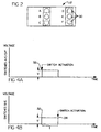
- FIG. 1 is an illustration of steering wheel control switches according to the principles of the present invention
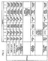
- Figure 3 is a table of steering wheel control switch functions mapped to different modules according to the principles of the present invention.
- Figure 4A is a graph of voltage versus time illustrating control switches A, C, D, and F activation according to the principles of the present invention.
- Figure 4B is a graph of voltage versus time illustrating control switches B and E activation according to the principles of the present invention.
- FIG. 1 there is shown a schematic view of a control system 10 in a motor vehicle having a steering wheel control switch system 12 in communication with a multiplexer 14 through bus 16.
- the multiplexer 14 in turn communicates two-way with a plurality of vehicle modules 18 through a CAN-B Bus Link Network 20.
- Other methods of communication for example a fiber optic network, may also be used so long as the method of communication provides for two-way communication between the multiplexer 14 and the plurality of vehicle modules 18.
- the plurality of vehicle modules 18, for example, includes a hands-free phone system 22, a satellite radio 24, a navigation radio (or navigation system) 26, and a video entertainment system 28.
- Other vehicle modules that can be connected to the multiplexer include an AM/FM radio, a cassette tape player, or a CH/CD-C player.
- the steering wheel control switch system 12 includes a plurality of control switches 30.
- control switches 30 In the particular example provided, six control switches have been illustrated, labeled A, B, C, D, E, and F, arranged in two columns. However, those skilled in the art will appreciate that any number of switches may be used and the switches may be arranged in any number of ways.
- Each of the switches A, B, C, D, E, and F has a unique voltage associated with its activation.
- the voltage travels through the bus 16 to the multiplexer 14.
- the multiplexer 14 measures the voltage to determine which one of the switches A, B, C, D, E, and F was activated.
- the multiplexer 14 assigns a function to the activated switch using a software interpreter, according to the table shown in Figure 3. Which function is assigned depends on which one of the switches A, B, C, D , E, and F was activated and which one of the plurality of vehicle modules 18 is currently active.
- the multiplexer 14 then sends the function through the Bus Link Network 20 to the active vehicle module 18.
- the active vehicle module 18 communicates that it is active to the multiplexer 14 through the Bus Link Network 20. Switching between active vehicle modules 18 is accomplished through the steering wheel control switch system 12.
- switches A, B, C, D, E, and F may each have different functions depending on which vehicle module 18 is active.
- switch B can be assigned a preset up function when the video entertainment system 28 is active, and can then be assigned a totally different function, for example an enter function, when the hands-free phone system 22 is active.
- Figure 3 shows the recommended assignment of functions to the switches A, B, C, D, E, and F according to which one of the vehicle modules 18 is active.
- various other functions may be assigned in any number of configurations to the switches A, B, C, D , E, and F.
- switches A, B, C, D, E, and F when one of switches A, B, C, D, E, and F are depressed, the switches A, B, C, D, E, and F send a specific voltage "v" to the multiplexer 14.
- Switches A, C, D, and F are activated as soon as the multiplexer 14 receives the voltage "v", indicated at point 32.
- switches B and E are not activated at point 32, but instead when the voltage sent to the multiplexer 14 ends, indicated at point 34.
- the time “t” that elapses from voltage start, point 32, to voltage end, point 34, determines what function is assigned to switches B and E.
- the time "t” is compared to a predetermined time value, for example two seconds.
- any amount of time may be used. If the time “t" is less than the predetermined time value of two seconds, a function is assigned to the activated switch. If the time "t" is greater than or equal to the predetermined time value of two seconds, then a different function is assigned to the activated switch. For example, referring again to Figure 3, if the navigation system 26 is active and switch B is activated, holding switch B for greater than two seconds will activate the hands-free phone system 22, while holding switch B for less than two seconds will send the enter function to the navigation system 26.
Landscapes
- Engineering & Computer Science (AREA)
- General Engineering & Computer Science (AREA)
- Theoretical Computer Science (AREA)
- Human Computer Interaction (AREA)
- Physics & Mathematics (AREA)
- General Physics & Mathematics (AREA)
- Steering Controls (AREA)
Applications Claiming Priority (2)
| Application Number | Priority Date | Filing Date | Title |
|---|---|---|---|
| US342508 | 1989-04-24 | ||
| US10/342,508 US20040138795A1 (en) | 2003-01-15 | 2003-01-15 | Reconfigurable steering wheel control switch system |
Publications (2)
| Publication Number | Publication Date |
|---|---|
| EP1445687A2 true EP1445687A2 (de) | 2004-08-11 |
| EP1445687A3 EP1445687A3 (de) | 2007-07-04 |
Family
ID=32655467
Family Applications (1)
| Application Number | Title | Priority Date | Filing Date |
|---|---|---|---|
| EP04000252A Withdrawn EP1445687A3 (de) | 2003-01-15 | 2004-01-08 | Rekonfigurierbare Steuerungsschaltung auf einem Lenkrad |
Country Status (2)
| Country | Link |
|---|---|
| US (1) | US20040138795A1 (de) |
| EP (1) | EP1445687A3 (de) |
Cited By (1)
| Publication number | Priority date | Publication date | Assignee | Title |
|---|---|---|---|---|
| WO2018086800A1 (en) * | 2016-11-11 | 2018-05-17 | Jaguar Land Rover Limited | Configurable user interface method and apparatus |
Families Citing this family (11)
| Publication number | Priority date | Publication date | Assignee | Title |
|---|---|---|---|---|
| US9035886B2 (en) | 2008-05-16 | 2015-05-19 | International Business Machines Corporation | System and apparatus for a multi-point touch-sensitive sensor user interface using distinct digit identification |
| US9035891B2 (en) | 2008-05-16 | 2015-05-19 | International Business Machines Corporation | Multi-point touch-sensitive sensor user interface using distinct digit identification |
| US20100073132A1 (en) * | 2008-09-19 | 2010-03-25 | Delphi Technologies, Inc. | Ignition system for a vehicle |
| TWI389018B (zh) * | 2008-12-30 | 2013-03-11 | Mstar Semiconductor Inc | 手持式電子裝置、手持式行動通訊裝置及其運作方法 |
| US8214105B2 (en) | 2009-08-21 | 2012-07-03 | Metra Electronics Corporation | Methods and systems for automatic detection of steering wheel control signals |
| US8014920B2 (en) * | 2009-08-21 | 2011-09-06 | Metra Electronics Corporation | Methods and systems for providing accessory steering wheel controls |
| US8285446B2 (en) | 2009-08-21 | 2012-10-09 | Circuit Works, Inc. | Methods and systems for providing accessory steering wheel controls |
| US20120283914A1 (en) * | 2011-05-05 | 2012-11-08 | Karwaczynski Krzysztof W | Vehicle steering wheel control system having integrated electronic control unit |
| US9619114B2 (en) | 2012-06-11 | 2017-04-11 | Automotive Data Solutions, Inc. | Method and system to configure an aftermarket interface module using a graphical user interface |
| JP5678948B2 (ja) * | 2012-12-12 | 2015-03-04 | 株式会社デンソー | 車両用表示装置およびプログラム |
| JP6433327B2 (ja) * | 2015-02-13 | 2018-12-05 | 株式会社デンソーテン | 車載機器操作装置および車載機器操作方法 |
Family Cites Families (18)
| Publication number | Priority date | Publication date | Assignee | Title |
|---|---|---|---|---|
| JPS59227535A (ja) * | 1983-06-04 | 1984-12-20 | Aisin Seiki Co Ltd | 集中制御式ステアリングホイ−ル装置 |
| US4792783A (en) * | 1986-05-07 | 1988-12-20 | Electro-Mechanical Products | Vehicular function controller having alterable function designators |
| US5555502A (en) * | 1994-05-11 | 1996-09-10 | Geo Ventures | Display and control apparatus for the electronic systems of a motor vehicle |
| US6373472B1 (en) * | 1995-10-13 | 2002-04-16 | Silviu Palalau | Driver control interface system |
| JPH1032883A (ja) * | 1996-07-16 | 1998-02-03 | Alps Electric Co Ltd | 車両用多重通信装置 |
| US5691695A (en) * | 1996-07-24 | 1997-11-25 | United Technologies Automotive Systems, Inc. | Vehicle information display on steering wheel surface |
| JPH1097821A (ja) * | 1996-08-01 | 1998-04-14 | Matsushita Electric Ind Co Ltd | 操作装置およびこれを用いた車載用機器の操作装置 |
| DE19631502C1 (de) * | 1996-08-03 | 1998-01-22 | Bosch Gmbh Robert | Lenkrad mit optoelektronischem Sensor |
| US5757268A (en) * | 1996-09-26 | 1998-05-26 | United Technologies Automotive, Inc. | Prioritization of vehicle display features |
| US6032089A (en) * | 1997-12-01 | 2000-02-29 | Chrysler Corporation | Vehicle instrument panel computer interface node |
| JP3692759B2 (ja) * | 1998-01-19 | 2005-09-07 | 株式会社デンソー | 車両用表示装置 |
| US7684570B2 (en) * | 1998-11-17 | 2010-03-23 | Aamp Of America | Vehicle remote control interface for controlling multiple electronic devices |
| IT1308466B1 (it) * | 1999-04-30 | 2001-12-17 | Fiat Ricerche | Interfaccia utente per un veicolo |
| US6511342B1 (en) * | 1999-08-17 | 2003-01-28 | Lear Corporation | Modular instrument panel system having a flat flexible bus |
| US6253131B1 (en) * | 1999-09-08 | 2001-06-26 | Paccar Inc | Steering wheel electronic interface |
| US6396164B1 (en) * | 1999-10-20 | 2002-05-28 | Motorola, Inc. | Method and apparatus for integrating controls |
| US6559773B1 (en) * | 1999-12-21 | 2003-05-06 | Visteon Global Technologies, Inc. | Reconfigurable display architecture with spontaneous reconfiguration |
| US6928350B2 (en) * | 2001-10-29 | 2005-08-09 | Visteon Global Technologies, Inc. | Control console for an automobile |
-
2003
- 2003-01-15 US US10/342,508 patent/US20040138795A1/en not_active Abandoned
-
2004
- 2004-01-08 EP EP04000252A patent/EP1445687A3/de not_active Withdrawn
Cited By (2)
| Publication number | Priority date | Publication date | Assignee | Title |
|---|---|---|---|---|
| WO2018086800A1 (en) * | 2016-11-11 | 2018-05-17 | Jaguar Land Rover Limited | Configurable user interface method and apparatus |
| US11241963B2 (en) | 2016-11-11 | 2022-02-08 | Jaguar Land Rover Limited | Configurable user interface method and apparatus |
Also Published As
| Publication number | Publication date |
|---|---|
| US20040138795A1 (en) | 2004-07-15 |
| EP1445687A3 (de) | 2007-07-04 |
Similar Documents
| Publication | Publication Date | Title |
|---|---|---|
| EP1560200B1 (de) | Verfahren und System zur Sprachdialogschnittstelle | |
| US6344793B1 (en) | Process for assisting a user of a motor vehicle when operating components of the motor vehicle as well as a pertaining system | |
| US20040138795A1 (en) | Reconfigurable steering wheel control switch system | |
| US6396164B1 (en) | Method and apparatus for integrating controls | |
| US6240347B1 (en) | Vehicle accessory control with integrated voice and manual activation | |
| US7006793B2 (en) | Safe use of electronic devices in an automobile | |
| US11551679B2 (en) | Multimodal dialog in a motor vehicle | |
| US20110263293A1 (en) | Mobile device interface for use in a vehicle | |
| EP0925989A3 (de) | Modulsystem auf Fahrzeug- Armaturenbrett | |
| RU2446961C2 (ru) | Система для отображения информации | |
| US20060095177A1 (en) | Operator control device for individually operating a motor vehicle device | |
| EP1676372B1 (de) | System zur verwaltung der mobilkommunikation | |
| JPH1097821A (ja) | 操作装置およびこれを用いた車載用機器の操作装置 | |
| US7457755B2 (en) | Key activation system for controlling activation of a speech dialog system and operation of electronic devices in a vehicle | |
| HK1206692A1 (en) | Method and apparatus for integration of factory and aftermarket vehicle components | |
| CN100579828C (zh) | 用于对汽车中的器具或系统进行语音控制的方法和装置 | |
| JP2000003652A (ja) | 車載用入力装置 | |
| US6629183B1 (en) | Interface device for transmitting information between input/output means | |
| KR20070008615A (ko) | 특히 차량을 위해, 목록 항목과 정보 시스템 또는엔터테인먼트 시스템을 선택하는 방법 | |
| US20090216389A1 (en) | Driver information device | |
| KR100836225B1 (ko) | 동적표시버튼을 적용한 자동차 스티어링 휠 리모컨장치 | |
| EP1350661B1 (de) | Gerät und Verfahren zur Erleichterung der Bedienung von Fahrzeugausstattungssystemen | |
| KR101148981B1 (ko) | 스티어링휠에 설치된 차량용 제어장치 | |
| US20060213755A1 (en) | Radio frequency wireless steering wheel | |
| US6718260B1 (en) | Reconfigurable menu display for a vehicle navigation system |
Legal Events
| Date | Code | Title | Description |
|---|---|---|---|
| PUAI | Public reference made under article 153(3) epc to a published international application that has entered the european phase |
Free format text: ORIGINAL CODE: 0009012 |
|
| AK | Designated contracting states |
Kind code of ref document: A2 Designated state(s): AT BE BG CH CY CZ DE DK EE ES FI FR GB GR HU IE IT LI LU MC NL PT RO SE SI SK TR |
|
| AX | Request for extension of the european patent |
Extension state: AL LT LV MK |
|
| RIN1 | Information on inventor provided before grant (corrected) |
Inventor name: LIU, SAM, K. Inventor name: JAWORSKI, DAVID, J. Inventor name: ALKARAWI, ATHEEL, S. |
|
| PUAL | Search report despatched |
Free format text: ORIGINAL CODE: 0009013 |
|
| AK | Designated contracting states |
Kind code of ref document: A3 Designated state(s): AT BE BG CH CY CZ DE DK EE ES FI FR GB GR HU IE IT LI LU MC NL PT RO SE SI SK TR |
|
| AX | Request for extension of the european patent |
Extension state: AL LT LV MK |
|
| RIC1 | Information provided on ipc code assigned before grant |
Ipc: B62D 33/073 20060101ALI20070530BHEP Ipc: G06F 3/023 20060101AFI20040617BHEP |
|
| AKX | Designation fees paid | ||
| STAA | Information on the status of an ep patent application or granted ep patent |
Free format text: STATUS: THE APPLICATION IS DEEMED TO BE WITHDRAWN |
|
| 18D | Application deemed to be withdrawn |
Effective date: 20080105 |
|
| REG | Reference to a national code |
Ref country code: DE Ref legal event code: 8566 |