EP1445830A1 - Antennenschaltung mit einer wirkungsvollen Abstrahlung - Google Patents
Antennenschaltung mit einer wirkungsvollen Abstrahlung Download PDFInfo
- Publication number
- EP1445830A1 EP1445830A1 EP03002485A EP03002485A EP1445830A1 EP 1445830 A1 EP1445830 A1 EP 1445830A1 EP 03002485 A EP03002485 A EP 03002485A EP 03002485 A EP03002485 A EP 03002485A EP 1445830 A1 EP1445830 A1 EP 1445830A1
- Authority
- EP
- European Patent Office
- Prior art keywords
- antenna
- port
- branch
- transmitter
- signal power
- Prior art date
- Legal status (The legal status is an assumption and is not a legal conclusion. Google has not performed a legal analysis and makes no representation as to the accuracy of the status listed.)
- Ceased
Links
- 230000005855 radiation Effects 0.000 title claims abstract description 12
- 230000005540 biological transmission Effects 0.000 claims abstract description 21
- 238000004891 communication Methods 0.000 claims description 8
- 238000010586 diagram Methods 0.000 description 4
- 230000001413 cellular effect Effects 0.000 description 1
- 238000010295 mobile communication Methods 0.000 description 1
- 239000000126 substance Substances 0.000 description 1
Images
Classifications
-
- H—ELECTRICITY
- H01—ELECTRIC ELEMENTS
- H01Q—ANTENNAS, i.e. RADIO AERIALS
- H01Q21/00—Antenna arrays or systems
- H01Q21/0006—Particular feeding systems
-
- H—ELECTRICITY
- H04—ELECTRIC COMMUNICATION TECHNIQUE
- H04B—TRANSMISSION
- H04B1/00—Details of transmission systems, not covered by a single one of groups H04B3/00 - H04B13/00; Details of transmission systems not characterised by the medium used for transmission
- H04B1/02—Transmitters
- H04B1/04—Circuits
- H04B1/0458—Arrangements for matching and coupling between power amplifier and antenna or between amplifying stages
Definitions
- the present invention relates to an antenna circuit for mobile terminals which can be used in wireless communication systems.
- it relates to an antenna circuit having two radiating components.
- a communication in wireless communication systems is based on radio links established between a mobile terminal and a base station or another mobile terminal of the respective system.
- a mobile terminal may be any electronic appliance adapted to exchange signals with a wireless communication system, like e.g. a Personal Digital Assistant (PDA), a mobile phone, a wireless measuring equipment or the like. There are two conditions to be distinguished for the radio link.
- PDA Personal Digital Assistant
- An uplink when the mobile terminal transmits a radio signal which is to be received by the respective base station or the other mobile terminal, and a downlink when the base station ort he other mobile terminal sends a radio signal to the mobile terminal.
- the signal strength received by either one of these appliances depends on the antenna power of the respective other appliance and the quality of the transmission path stretching between the two.
- the quality of the transmission path varies on mobile transmission conditions usually within very short time periods.
- the antenna power of the transmitting appliance i.e. either the mobile terminal or the base station
- the antenna power is set low for a good transmission quality and set high for a bad one.
- the energy available on a mobile terminal is limited by its battery capacity.
- the transmitter circuitry of a mobile terminal has to be laid out for high radiation efficiency. This means, that the signal power supplied from the power amplifier of the transmitter has to be converted by the antenna into radiation energy at very low loss conditions. This is usually accomplished by matching the antenna branch impedance of the transmitter with that of its power amplifier output.
- the impedance of the antenna branch is not a fixed constant as it varies with any variations in its surroundings. Any such variation causes a mismatch in the transmission circuitry.
- the antenna branch of a mobile terminal transmitter is usually designed for free field conditions. Under usual operating conditions, when a user covers at least part of the antenna with some part of his body, like his hand a mismatch is therefore most commonly produced. As an actual antenna mismatch due to influences from the surroundings of a mobile terminal can generally not be predicted, the transmitter of a common mobile terminal will operate most of the time below its optimum efficiency which results in an excessive consumption of the limited energy resources provided by the battery of the mobile phone.
- an antenna circuit for improving the radiation efficiency of a transmitter with a first antenna branch having a first antenna for emitting a transmission signal provided by a power amplifier of the transmitter, a redirection means for redirecting a part of the transmission signal power reflected at the first antenna branch of the transmitter to a second antenna branch, and a second antenna for emitting the part of the transmission signal power redirected to the second antenna branch.
- Allowing the reflected energy of a mismatched antenna branch to be emitted via a second radiating component increases the radiation efficiency of a transmitter in a simple but effective way.
- An antenna circuit as proposed is particularly useful for transmitters of mobile terminals which are operated under continuously changing ambient conditions.
- a second redirection means is advantageously placed in the second antenna branch for redirecting a part of the transmission signal power reflected at the second antenna to a load and for routing the part of the transmission signal power received from the first redirection means to the second antenna.
- the transmission signal energy is effectively transferred to the radiating components while any signal energy which cannot be emitted is directly forwarded to a load for being consumed.
- the first and/or second redirection means is effectively formed by a three-port power distributor which routes a signal power received on a first port to a second port connected to an antenna branch or an antenna and which forwards a signal power received on the second port to a third port.
- the three-port power distributor is hereby particularly advantageously formed by a three-port circulator, as it just distributes the energy with practically no loss.
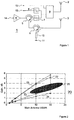
- the block diagram of Fig. 1 shows an example for an antenna circuitry 1 according to the present invention.
- the power amplifier 4 receives an RF (radio frequency) signal from a signal processing stage of a respective appliance at its input port 14.
- the gain of the power amplifier 4 is usually controlled according to feedback information received from the base station to which a radio link has been established. It is set to a value such, that the transmission level guarantees a sufficiently strong RF signal at the base station.
- the energy consumed for that purpose is provided from a battery arrangement, which is e.g. part of a battery pack of the mobile terminal.
- the circuitry 1 shown in Fig. 1 is designed for a multiband transceiver for such a mobile terminal.
- an antenna switch 9 is used to connect the main antenna 2 with the input 12 of a receiver circuitry not shown in block diagram 1. Under uplink conditions, the antenna switch 9 connects the main antenna 2 with the circuitry at the output of power amplifier 4.
- the frequency bands reserved for an UMTS uplink are located below those reserved for an UMTS downlink.
- the received signal can be separated from the transmitted signal by means of filters as shown in Fig. 1.
- An RF signal like e.g. a WCDMA (Wideband Code Division Multiple Access) coded signal received on an UMTS downlink is blocked off by the low pass filter 7 and supplied to an input 13 of the receiving section of the transceiver for further processing after passing the high pass filter 8.
- the RF signals provided by the power amplifier 4 can pass the low pass filter 7 for being emitted by the main antenna 2 but are blocked off by the high pass filter 8 so that the will not overload the receiving section. This applies to all frequency bands for which the transceiver is laid out, as the frequency bands for GSM, DCS and PCS systems are all located below the UMTS frequencies.
- a three-port power distributor like for instance a three-port circulator 5 is set between the output of the power amplifier 4 and the low pass filter 7. As indicated by an arched, dashed lined arrow, the circulator 5 routes the signal supplied from the power amplifier 4 directly to its port which is connected with the main antenna 2.
- the main antenna 2 together with the circuitry interconnecting it to the circulator 5 will further be referred to as main antenna branch; any mismatch between an antenna, its interconnecting circuitry and the power amplifier 4 is defined as an antenna mismatch. Under mismatch conditions, part of the signal energy provided by the power amplifier 4 is reflected back from the antenna branch. The signal power radiated by the antenna is therefore less than the signal power supplied.
- the signal power reflected from the main antenna branch enters the circulator 5 at the port connected to the low pass 7 and is therein passed on to the third port interconnected with the additional antenna 3 as indicated by the respective dashed, curved arrow.
- the third port of the circulator 5 is directly connected to an additional antenna 3 which will at emit at least part of the signal power reflected from the main antenna 2.
- the radiation efficiency of the additional antenna 3 depends on the matching conditions of the additional antenna branch. Depending on the degree of a possible mismatch, a bigger or smaller amount of the signal power supplied will be reflected. Therefore a second circulator 6 is placed in the line from the third port of circulator 5 to the additional antenna 3.
- the load 10 is preferably formed by an ohmic impedance, like a 50 Ohm resistor or the like for a matched termination of the third port of circulator 6.
- the additional antenna 3 is operated under perfectly matched conditions.
- the improvement of the radiation efficiency is achieved by redirecting the signal energy reflected from a mismatched main antenna 2 to an additional antenna from which an additional fraction of the signal energy is emitted.
- the main antenna 2 and the additional antenna 3 are preferably arranged at a certain distance to each other. Such an arrangement would further allow to implement a space diversity capability.
- Fig. 2 shows the calculated system gain of an antenna circuit according to the block diagram of Fig. 1.
- Any antenna mismatch i.e. the mismatch between the power amplifier and its load, the antenna branch is commonly qualified by a VSWR (Voltage Standing Wave Ratio) value defining the ratio of maximum to minimum voltage in a standing wave pattern.
- the chart 20 shows the system gain achieved in dB versus the main antenna mismatch in VSWR with the mismatch of the additional antenna as parameter.
- the VSWR for graph 22 is 2, for graph 23 its is 10, and for graph 24 its value is 15.
- the best improvement of the radiation efficiency or system gain, respectively is achieved for a seriously mismatched main antenna 2 with a VSWR of 10 or higher and a moderately mismatched additional antenna 3 showing a VSWR below 6.
- the working area 25 indicates the region for typical operation conditions. With a system gain of around 3 dB, the radiation efficiency is about doubled.
Landscapes
- Engineering & Computer Science (AREA)
- Computer Networks & Wireless Communication (AREA)
- Signal Processing (AREA)
- Transmitters (AREA)
Priority Applications (2)
| Application Number | Priority Date | Filing Date | Title |
|---|---|---|---|
| EP03002485A EP1445830A1 (de) | 2003-02-05 | 2003-02-05 | Antennenschaltung mit einer wirkungsvollen Abstrahlung |
| PCT/EP2004/000567 WO2004070877A1 (en) | 2003-02-05 | 2004-01-23 | Radiation efficient antenna circuit |
Applications Claiming Priority (1)
| Application Number | Priority Date | Filing Date | Title |
|---|---|---|---|
| EP03002485A EP1445830A1 (de) | 2003-02-05 | 2003-02-05 | Antennenschaltung mit einer wirkungsvollen Abstrahlung |
Publications (1)
| Publication Number | Publication Date |
|---|---|
| EP1445830A1 true EP1445830A1 (de) | 2004-08-11 |
Family
ID=32605334
Family Applications (1)
| Application Number | Title | Priority Date | Filing Date |
|---|---|---|---|
| EP03002485A Ceased EP1445830A1 (de) | 2003-02-05 | 2003-02-05 | Antennenschaltung mit einer wirkungsvollen Abstrahlung |
Country Status (2)
| Country | Link |
|---|---|
| EP (1) | EP1445830A1 (de) |
| WO (1) | WO2004070877A1 (de) |
Families Citing this family (2)
| Publication number | Priority date | Publication date | Assignee | Title |
|---|---|---|---|---|
| WO2007060487A1 (en) | 2005-11-28 | 2007-05-31 | Bae Systems Plc | Improvements relating to antenna arrays |
| WO2014120154A1 (en) * | 2013-01-30 | 2014-08-07 | Nokia Corporation | An apparatus for, at least, transmitting in a radio communications channel |
Citations (5)
| Publication number | Priority date | Publication date | Assignee | Title |
|---|---|---|---|---|
| JPS6124334A (ja) * | 1984-07-12 | 1986-02-03 | Nec Corp | 無線通信装置 |
| US5027125A (en) * | 1989-08-16 | 1991-06-25 | Hughes Aircraft Company | Semi-active phased array antenna |
| JPH03173206A (ja) * | 1989-12-01 | 1991-07-26 | Nippon Telegr & Teleph Corp <Ntt> | アンテナ装置 |
| EP0741463A2 (de) * | 1995-05-04 | 1996-11-06 | Nippondenso Co., Ltd. | Halbduplexfunkgerät mit niedriger Dämpfung des Sendesignals |
| US6466773B1 (en) * | 1997-05-15 | 2002-10-15 | Harris Corporation | Reflective power splitter for redundant receivers |
-
2003
- 2003-02-05 EP EP03002485A patent/EP1445830A1/de not_active Ceased
-
2004
- 2004-01-23 WO PCT/EP2004/000567 patent/WO2004070877A1/en not_active Ceased
Patent Citations (5)
| Publication number | Priority date | Publication date | Assignee | Title |
|---|---|---|---|---|
| JPS6124334A (ja) * | 1984-07-12 | 1986-02-03 | Nec Corp | 無線通信装置 |
| US5027125A (en) * | 1989-08-16 | 1991-06-25 | Hughes Aircraft Company | Semi-active phased array antenna |
| JPH03173206A (ja) * | 1989-12-01 | 1991-07-26 | Nippon Telegr & Teleph Corp <Ntt> | アンテナ装置 |
| EP0741463A2 (de) * | 1995-05-04 | 1996-11-06 | Nippondenso Co., Ltd. | Halbduplexfunkgerät mit niedriger Dämpfung des Sendesignals |
| US6466773B1 (en) * | 1997-05-15 | 2002-10-15 | Harris Corporation | Reflective power splitter for redundant receivers |
Non-Patent Citations (2)
| Title |
|---|
| PATENT ABSTRACTS OF JAPAN vol. 010, no. 175 (E - 413) 20 June 1986 (1986-06-20) * |
| PATENT ABSTRACTS OF JAPAN vol. 015, no. 417 (E - 1125) 23 October 1991 (1991-10-23) * |
Also Published As
| Publication number | Publication date |
|---|---|
| WO2004070877A1 (en) | 2004-08-19 |
Similar Documents
| Publication | Publication Date | Title |
|---|---|---|
| EP1508199B1 (de) | Drahtloses endgerät | |
| US5822684A (en) | Antenna switching circuit and wireless communication system | |
| KR101031692B1 (ko) | 무선 통신 장치, 무선 통신 방법, 안테나 장치 및 제 1듀플렉서 | |
| US6980782B1 (en) | Antenna device and method for transmitting and receiving radio waves | |
| US8441410B2 (en) | Multi-antenna system feed device and wireless link terminal equipped with such a device | |
| KR100908630B1 (ko) | 적어도 두 개의 주파수 밴드에서 선택적으로 변환하기 위한단말기, 관련된 변환기부 및 방법 | |
| KR100470582B1 (ko) | 다중 대역 전송을 위한 방법 및 장치 | |
| US7583934B2 (en) | Transceiver apparatus for use in a multi-frequency communication system, base station of a multi-frequency communication system, method for use of the transceiver apparatus, method of transceiving a multi-frequency signal in a multi-frequency communication system | |
| JP4425711B2 (ja) | アンテナ制御方法および無線送受信装置 | |
| US7853290B2 (en) | Transmitter arrangement | |
| EP2134000B1 (de) | Multiband-Mobilkommunikationsgerät | |
| CN102545946A (zh) | 射频前端电路 | |
| EP1289159A2 (de) | Hochfrequenzschalteinrichtung und mobiles Kommunikationsgerät | |
| US20020006810A1 (en) | Antenna changeover switch for transmit-receive units in a mobile station | |
| EP3811520B1 (de) | Funkeinheit für nichtsynchronisierten tdd-multiband-betrieb | |
| US6128508A (en) | Communications system using multi-band amplifiers | |
| RU2164056C1 (ru) | Абонентская станция с дуплексным антенным усилителем (варианты) | |
| EP1445830A1 (de) | Antennenschaltung mit einer wirkungsvollen Abstrahlung | |
| WO2019244757A1 (ja) | 高周波増幅回路および通信装置 | |
| EP1156582A2 (de) | Impedanzoptimierung von einer Sende-/ Empfangskette | |
| US20080161055A1 (en) | Base station architecture using decentralized duplexers | |
| US20090289872A1 (en) | High Power Ultra-Linear TDD Switch | |
| KR20060032365A (ko) | 듀얼모드 안테나 경로설정장치를 갖는 이동통신단말기 | |
| KR100294980B1 (ko) | 신호경로의길이가조절가능한분포정수라인을이용한rf스위치 | |
| EP1253723A1 (de) | Sender/Empfänger mit rekonfigurierbarer Ausgangskombination |
Legal Events
| Date | Code | Title | Description |
|---|---|---|---|
| PUAI | Public reference made under article 153(3) epc to a published international application that has entered the european phase |
Free format text: ORIGINAL CODE: 0009012 |
|
| AK | Designated contracting states |
Kind code of ref document: A1 Designated state(s): AT BE BG CH CY CZ DE DK EE ES FI FR GB GR HU IE IT LI LU MC NL PT SE SI SK TR |
|
| AX | Request for extension of the european patent |
Extension state: AL LT LV MK RO |
|
| 17P | Request for examination filed |
Effective date: 20040713 |
|
| 17Q | First examination report despatched |
Effective date: 20041007 |
|
| AKX | Designation fees paid |
Designated state(s): AT BE BG CH CY CZ DE DK EE ES FI FR GB GR HU IE IT LI LU MC NL PT SE SI SK TR |
|
| STAA | Information on the status of an ep patent application or granted ep patent |
Free format text: STATUS: THE APPLICATION HAS BEEN REFUSED |
|
| 18R | Application refused |
Effective date: 20051206 |