EP1445839B1 - System und zum verhindern elektrischer bogen in verbindern, die stromladungen liefern - Google Patents
System und zum verhindern elektrischer bogen in verbindern, die stromladungen liefern Download PDFInfo
- Publication number
- EP1445839B1 EP1445839B1 EP01974354A EP01974354A EP1445839B1 EP 1445839 B1 EP1445839 B1 EP 1445839B1 EP 01974354 A EP01974354 A EP 01974354A EP 01974354 A EP01974354 A EP 01974354A EP 1445839 B1 EP1445839 B1 EP 1445839B1
- Authority
- EP
- European Patent Office
- Prior art keywords
- terminals
- connector
- power
- pair
- connectors
- Prior art date
- Legal status (The legal status is an assumption and is not a legal conclusion. Google has not performed a legal analysis and makes no representation as to the accuracy of the status listed.)
- Expired - Lifetime
Links
- 238000001514 detection method Methods 0.000 claims description 44
- 238000010891 electric arc Methods 0.000 claims description 14
- 230000008878 coupling Effects 0.000 claims description 8
- 238000010168 coupling process Methods 0.000 claims description 8
- 238000005859 coupling reaction Methods 0.000 claims description 8
- 238000000926 separation method Methods 0.000 claims description 7
- 238000006073 displacement reaction Methods 0.000 claims description 5
- 239000004020 conductor Substances 0.000 claims description 4
- 230000007704 transition Effects 0.000 claims description 3
- 230000008859 change Effects 0.000 claims description 2
- 230000015572 biosynthetic process Effects 0.000 description 7
- 238000010586 diagram Methods 0.000 description 5
- 230000007246 mechanism Effects 0.000 description 3
- 238000000034 method Methods 0.000 description 3
- 230000006378 damage Effects 0.000 description 2
- 230000006866 deterioration Effects 0.000 description 2
- 230000000694 effects Effects 0.000 description 2
- 239000000463 material Substances 0.000 description 2
- 239000000523 sample Substances 0.000 description 2
- 208000027418 Wounds and injury Diseases 0.000 description 1
- 230000009471 action Effects 0.000 description 1
- 230000008901 benefit Effects 0.000 description 1
- 230000001419 dependent effect Effects 0.000 description 1
- 230000009977 dual effect Effects 0.000 description 1
- 238000010348 incorporation Methods 0.000 description 1
- 208000014674 injury Diseases 0.000 description 1
- 230000003287 optical effect Effects 0.000 description 1
- 230000009528 severe injury Effects 0.000 description 1
- 238000002604 ultrasonography Methods 0.000 description 1
Images


Classifications
-
- H—ELECTRICITY
- H01—ELECTRIC ELEMENTS
- H01R—ELECTRICALLY-CONDUCTIVE CONNECTIONS; STRUCTURAL ASSOCIATIONS OF A PLURALITY OF MUTUALLY-INSULATED ELECTRICAL CONNECTING ELEMENTS; COUPLING DEVICES; CURRENT COLLECTORS
- H01R13/00—Details of coupling devices of the kinds covered by groups H01R12/70 or H01R24/00 - H01R33/00
- H01R13/46—Bases; Cases
- H01R13/53—Bases or cases for heavy duty; Bases or cases for high voltage with means for preventing corona or arcing
-
- H—ELECTRICITY
- H01—ELECTRIC ELEMENTS
- H01R—ELECTRICALLY-CONDUCTIVE CONNECTIONS; STRUCTURAL ASSOCIATIONS OF A PLURALITY OF MUTUALLY-INSULATED ELECTRICAL CONNECTING ELEMENTS; COUPLING DEVICES; CURRENT COLLECTORS
- H01R13/00—Details of coupling devices of the kinds covered by groups H01R12/70 or H01R24/00 - H01R33/00
- H01R13/648—Protective earth or shield arrangements on coupling devices, e.g. anti-static shielding
- H01R13/6485—Electrostatic discharge protection
-
- H—ELECTRICITY
- H01—ELECTRIC ELEMENTS
- H01R—ELECTRICALLY-CONDUCTIVE CONNECTIONS; STRUCTURAL ASSOCIATIONS OF A PLURALITY OF MUTUALLY-INSULATED ELECTRICAL CONNECTING ELEMENTS; COUPLING DEVICES; CURRENT COLLECTORS
- H01R33/00—Coupling devices specially adapted for supporting apparatus and having one part acting as a holder providing support and electrical connection via a counterpart which is structurally associated with the apparatus, e.g. lamp holders; Separate parts thereof
- H01R33/74—Devices having four or more poles, e.g. holders for compact fluorescent lamps
- H01R33/76—Holders with sockets, clips, or analogous contacts adapted for axially-sliding engagement with parallely-arranged pins, blades, or analogous contacts on counterpart, e.g. electronic tube socket
- H01R33/7678—Holders with sockets, clips, or analogous contacts adapted for axially-sliding engagement with parallely-arranged pins, blades, or analogous contacts on counterpart, e.g. electronic tube socket having a separated part for spark preventing means
Definitions
- the present invention refers to a system for preventing the formation of electric arcs in connectors interspersed in an electric power distribution network, particularly applicable to a network assembled in an automotive vehicle for feeding power loads, such as a 42V network of a vehicle with two voltage levels (14V and 42V, or dual voltage system) for the purpose of preventing that, when the connector components are fortuitously or accidentally separated, or due to a lack of warning of a handler, an electric arc between contact points is generated which causes destruction or early deterioration of said contacts, or of the connector itself, an ill-timed interruption of the feed to certain loads of the network, or a fire situation with more or less severe damage, especially during the disconnection of the two electroinsulating parts or supports, components of a connector, bearing the electroconductive contact terminals.
- the invention is also especially interesting for electric vehicles in which a set of batteries is used to provide power to an electric motor intended for driving the vehicle, and in which the current levels are in the range of 400 A at 400 V for DC, and 40 A at 220 V for AC, which current and voltage values require the incorporation of a series of safety measures for minimizing the risk of injuries to users, mechanics and safety technicians.
- the invention also refers to a method for preventing the formation of electric arcs, as well as to a connector used in said system and method.
- Patents EP-A-697751, EP-A-673085 and US-A-6,146,160 disclose connectors with means for an effective mechanical clamping of the connection terminals, typically pins and electroconductive sockets, such that an accidental disconnection thereof cannot occur.
- US Patents 3,945,699, 4,749,357 and 5,676,571 disclose means associated to the electroconductive pin receiver females, provided for obstructing or minimizing electric arc formation when connecting the two connector components.
- US Patent B1-6,225,153 discloses a universal charge port connector for electric vehicles, in which a mechanism is provided for cutting off the current susceptible to generating an arc during disconnection of the male and female terminals of the connector before decoupling of the two component parts of said connector, particularly for preventing the disconnection of the connectors while charging vehicle batteries, which mechanism includes a mechanical lock of said two parts actuated by a lever which is associated to a switch coupled to a power source for the connector assembly, through which switch, and when the lever is actuated by a user, current circulation towards the power load to be fed is disabled before enabling the disconnection of the male-female power terminal or terminals of the connector.
- US patent 5,542,425 discloses an apparatus and method for preventing the deterioration of the contacts in electric equipment, specifically in image acquisition equipment with an ultrasound system in which several probes can be linked to the acquisition system with no risk of an electric arc being able to jump when disconnecting said probes, in which system the connector includes a mechanically actuated element for actuating and deactivating a connection interface between components, including a sensor or detector determining when the connector is going to be disconnected by one of the components, and provides a signal used by one of the components for disabling the electric power feed to the connector and thus preventing electric arc formation upon physically separating the male-female terminals thereof.
- said element is a rotating shaft which the user must act on
- said sensor is an optical sensor, magnetic sensor or simple switch.
- the feed source disconnection is carried out either by the user (as in US-B1-6,225,153) or by means of the addition of a sensor associated to a mechanism likewise actuated by the user (as in US-A-5,542,425), being necessary to always act on the connector with means for suitably moving its contacts, delay generation being essential for suitable functioning due to the mechanical actuation conditions.
- Document EP-A-0 602 804 discloses a system according to the preamble of claim 1.
- the system of claim 1 provides for an electronic unit susceptible to individually controlling a plurality of different connectors interspersed at different points of the network for electric current distribution towards the power loads.
- the system for preventing electric arcs comprises a load 10 to be fed and a feed line 17 connected by an electric power through channel 5, 6, a protection device 7 of the load 10 by disconnection of the feed line 17, and a connector 11 arranged on said channel 5, 6 between the device 7 and the load 10.
- the connector 11 is of the type comprising first and second releasable electroinsulating connection supports 1, 2 capable of mutual socket coupling, which carry a pair of power terminals 3, 4 connected to respective branches 5, 6 of the electric power through channel from the device 7 to the load 10.
- the electroinsulating supports 1, 2 of the connector 11 can adopt a first definitive coupling position A in which the terminals 3, 4 are electrically coupled together, forming said electric power through channel 5, 6, and a second total decoupling position C in which the terminals 3, 4 are physically separated.
- the feed network voltage level is high enough so as to generate an electric arc when said separation of the terminals 3, 4 is carried out.
- the system of the invention includes a pair of additional electroconductive elements 12, 13 in the connector 11 which carry out a detection function of an intermediate position B of the electroinsulating supports 1, 2 located at a point of the decoupling displacement or run thereof between said first and second positions A and C.
- an intermediate position B of the electroinsulating supports 1, 2 located at a point of the decoupling displacement or run thereof between said first and second positions A and C.
- Said intermediate position B detection is carried out by means described below in reference to figures 4a to 7c.
- Said additional electroconductive elements 12, 13 are associated to an auxiliary electric circuit 14, 15 through which, and when detection of intermediate position B of the electroinsulating supports 1, 2 is carried out, an electric warning signal will be generated by virtue of which said disconnection protection device 7 immediately interrupts the electric feed towards the load 10 through said channel 5, 6 and, accordingly, the terminals 3, 4, before these reach said second position C of mutual physical separation. Therefore, when the decoupling run continues between the electroinsulating supports 1, 2 from intermediate position B, there is no longer current passing through the terminals 3, 4, and an electric arc jump is impossible when the physical separation between both of them is carried out upon having reached the second position C.
- said disconnection protection device 7 comprises, for example, a power relay represented as a switch 18 controlled by a coil 19.
- a power relay represented as a switch 18 controlled by a coil 19.
- One of the detection terminals 13 of said pair of addition terminals 12, 13 of the connector 11 is connected to a ground connection 14, and said detection signal comprises the change from a minimum impedance situation, distinctive of the connection to said ground connection 14, to a maximum impedance situation in the conductor 15 when said ground connection is cut off.
- the load 10 and connector 10 are identical to those described above in relation to figure 1, whereas here, the disconnection protection device 7 is integrated in an electronic unit 20 or distribution box with the functioning of at least one microprocessor, in other words, a "smart" unit controlling the connector 11.
- Said unit 20 comprises an circuit 16 for identification of the connector 11 in intermediate position B, that is, in transition towards the second decoupling position C, which circuit 16 is connected to a microprocessor 8 controlling said disconnection protection device 7 which is linked to the electric power feed source by means of the feed line 17.
- the disconnection protection device 7 can be constituted of a power relay or FET power transistor and is connected to the load 10 through channel 5, 6 and terminals 3, 4 of the connector 11. The advantage of this configuration is that it is adapted for feeding and controlling several loads individually.
- the diagram in figure 3 shows the system of the present invention in which there is a plurality of loads to be fed, which in figure 3 are represented by only two loads 10a, 10b for greater simplicity of the drawing.
- a corresponding connector 11a, 11b provided with its pair of power terminals 3, 4 and its pair of additional terminals 12, 13, one of which is connected to the corresponding ground connection 14.
- lid Between these connectors 11a and 11b and the electronic unit 20, there are other connectors lie, lid, each one of which comprises two pairs of terminals 3, 4 and a pair of additional terminals 12, 13 for connection to ground connection 14.
- a distribution connector 11e is arranged, in this example provided with six pairs of terminals 3, 4 and a pair of addition terminals 12, 13 for connection to ground connection 14.
- the feed channels 5, 6 are arranged on one side from the disconnection protection device 7 towards the corresponding loads 10a and 10b, and the connections of the multiple ground connections 14 to the identification circuit 16 are arranged on the other side.
- the number of terminals 3, 4 in the connectors 11a, ..., 11e increases as the connector gets closer to the electronic unit 20.
- the closer the connector is to the distribution connector 11e it will be hierarchically preferential with regard to the other successive connectors of the same line in which it is incorporated.
- the identification circuit 16 is able to identify the connector or connectors 11a, ..., 11e which is in said intermediate position B, that is, in transition towards decoupling position C, by virtue of the signal it receives from the circuit or circuits connected to the respective ground connections and, according to which is the connector 11a, ..., 11e from which the warning signal is received, it acts on the microprocessor 8 by sending a preferential interruption which generates from this microprocessor 8 a corresponding order to the disconnection protection device 7, which cuts off the feed to the corresponding load or loads 10a, 10b through the power channel or channels 5, 6 and terminals 3, 4 of the connector or connectors 11a, ..., 11e involved.
- the connectors 11a, ..., 11e are of multiple contacts, besides the additional detection contacts, which are assembled through a series of terminal pairs.
- the connectors 11c and 11d only a pair of terminals 3, 4 are power terminals, whereas the other pair of terminals serves to connect detection lines of other connectors, whereas the distribution connector 11e is connected to two feed channels 5, 6 of power loads 10a, 10b through other pairs of power terminals 3, 4, including a single pair of additional detection terminals 12, 13 which protect all the power terminals 3, 4 of said distribution connector 11e from the formation of electric arcs in cooperation with the electronic unit 20.
- the other pairs of terminals in the distribution connector 11e serve only for the connection of the lines coupled to ground connections 14 in other system connectors. Accordingly, it is possible, to provide connectors according to the present invention provided with multiple power contacts and generally with a single detection contact.
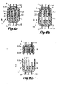
- Figures 4a to 6c show first, second and third embodiment examples of the connector 11 of the present invention.
- the connector 11 always comprises two supports 1, 2 of an electroinsulating material, which carry, in the example shown, two pairs of power terminals 3, 4 connected to respective power feed channel spans 5, 6 and a pair of additional terminals 12, 13 connected respectively to the detection line 15 and ground connection 14.
- Each one of the terminals is composed of a male pin 3, 12 and a female base 4, 13 susceptible to being coupled together.
- the elements of the pairs of terminals 3, 4 and 12, 13 are arranged on the mutually facing respective supports 1, 2 such that when said supports 1,2 are coupled, all the terminal pair elements are connected together.
- the first and second electroinsulating supports 1, 2 of the connector 11 comprise mechanical closure means of mutual coupling thereof consisting of projections 21 formed on several resilient arms 22 joined to the first support 1 and first and second notches 23a, 23b incorporated on the second support 2.
- the projections 21, by virtue of the resilient force of the arms 22, are first housed in the first notches 23a, momentarily retaining the supports 1, 2 in this position, and then in the second notches 23b.
- decoupling is carried out in two steps: a first step in which a displacement occurs until the projections 21 are housed in the second notches 23b, and a second step until the complete separation of the supports 1, 2.
- the male pins 3, 12 respectively corresponding to the power and detection terminals have a same length, whereas the female base 13 of the detection terminal is shorter than the female bases of the power terminals.
- a first definitive coupling position A shown in figure 4a the projections 21 are housed in the second notches 23b, and both the power terminals 3, 4 and detection terminals 12, 13 are coupled.
- an intermediate position B shown in figure 4b the projections 21 are housed in the first notches 23a, and the power terminals 3, 4 remain coupled, whereas the detection terminals 12, 13 have been disconnected, that is, they have lost contact with one another.
- the auxiliary circuit 14, 15 is open and a detection signal is generated as has been described above with reference to figures 1 to 3, by virtue of which signal the system cuts off the power current of the circuit 5, 6. Accordingly, in intermediate position B, even though the power terminals 3, 4 are still mutually connected, no electric current passes through them and they are not live.
- the male pins 3, 12 respectively corresponding to the power and detection terminals have a same length like their respective female bases 4, 13, even though the female base 13 of the detection terminal is more withdrawn than the female bases of the power terminals.
- the material of the second electroinsulating support 2 is also withdrawn from the entry area of the female base 13, leaving a stepped cavity or recess, when the supports 1, 2 are coupled (figure 5a).
- Positions A, B and C of this second embodiment example are similar to positions A, B and C of the first embodiment example shown in figures 4a, 4b and 4c, and they produce the same effects, therefore their description has been omitted.
- the male pin 12 corresponding to the detection terminals is shorter than the male pins 3 of the power terminals, whereas their respective female bases 4, 13 all have the same length.
- Positions A, B and C of this third embodiment example, shown respectively in figures 6a, 6b and 6c, are similar to positions A, B and C of the first embodiment example shown in figures 4a, 4b and 4c, and they produce the same effects, therefore their description has been omitted.
- Figures 7a to 7c show a fourth embodiment example in which the power terminals adopt the shape of two pairs of male pin 3 and female base 4, whereas the detection terminals include an electroconductive part 30 fixed to the first electroinsulating support 1 of the connector 11 and two spaced conducting strips 32a, 32b fixed to the second support 2 of the connector 11 in a position such that said electroconductive part 30, during the coupling and decoupling of the first and second supports 1, 2, overlaps and bridges said strips 32a, 32b.
- two branches 31a, 31b of the electric detection circuit connected to the ground connection 14 and the connection channel 15 to the electronic unit 20 are arranged inside of the second support 2.
- the second support 2 incorporates a single resilient arm 22 with a projection 21, and the first support 1 incorporates said first and second notches 23a and 23b on the corresponding side.
- the first and second electroinsulating supports 1, 2 are coupled, the projection 21 is housed in the second notch 23b, and the power terminals 3, 4 are completely connected.
- the electroconductive part 30, which adopts the shape of an resilient projection, is housed in a notch 33 formed on the second support 2 of the connector 11, at a suitable distance from the two conductive strips 32a, 32b which together form another notch or recess. Accordingly, the electric detection circuit formed by the two branches 31a, 31b is open and current does not circulate between the ground connection 14 and the connection channel 15.
- an intermediate position B shown in figure 7b the projection 21 is housed in the first notch 23a, and the power terminals 3, 4 remain coupled.
- the electroconductive part 30 is housed in the notch or recess formed between the two conductive strips 32a, 32b, forming a bridge contact between them such that the electric detection circuit formed by the two branches 31a, 31b is closed and current circulates from the ground connection 14 towards the electronic unit 20 through the connection channel 15.
- This generates a detection signal upon changing from a maximum impedance situation in the conductor 15 to a minimum impedance situation, distinctive of the connection to said ground connection 14, opposite of how it has been described above with reference to figure 1.
- the system cuts off the power current of the circuit 5, 6. Accordingly, in intermediate position B, even though the power terminals 3, 4 are mutually connected, current does not pass through them and they are not live.
- detection contacts 12, 13 and 30, 31a, 31b associated to an auxiliary circuit are included in addition to the power terminals 3, 4.
- the decoupling action of the first and second electroinsulating supports 1, 2 of the connector 11 is preferably carried out in two steps, with the aid of said notch configurations. In a first step, a displacement between the first and second supports 1, 2 occurs until overcoming a threshold in the decoupling run which generates a momentary or permanent disconnection or connection of detection contacts 12, 13; 30, 31a, 31b without there being a disconnection of the power terminals 3, 4.
- Said momentary or permanent disconnection or connection of the detection contacts 12, 13; 30, 31a, 31b generates a signal used by the control unit to cut off the current to the power terminals 3, 4.
- the definitive disconnection of the pair of power terminals 3, 4 is produced with no risk of an electric arc being generated, since current no longer passes through them.
Landscapes
- Details Of Connecting Devices For Male And Female Coupling (AREA)
Claims (15)
- System zur Vermeidung von Lichtbögen bei Verbindern, die Leistungsbelastungen liefern, das Verbinder (11) umfasst, wobei die Verbinder (11) in ein Netz zur Verteilung von elektrischer Energie und zur Versorgung mit elektrischer Energie eingeschaltet sind, sie sind der Art, dass sie erste und zweite Träger (1 und 2) zur elektroisolierenden Verbindung über eine Steckverbindung umfassen, in der Weise, dass sie getrennt werden können, die mindestens ein Paar von Leistungsklemmen (3,4) tragen, die in einer ersten Position A der endgültigen Verbindung elektrisch untereinander verbunden sind, um einen Kanal (5,6) zur Durchführung zur Versorgung oder für elektrische Energie zu bilden, bis zu einer entsprechenden Belastung (10) mit Energie, und deren Leistungsklemmen (3,4) in einer zweiten Position C der Trennung der Träger (1,2) zur elektroisolierenden Verbindung physisch getrennt sind, wobei das Niveau der Spannung des besagten Netzes so ist, dass die besagte Trennung einen Lichtbogen erzeugen kann, wobei jeder der besagten Verbinder (11) mindestens ein Paar zusätzlicher, elektrisch leitfähiger Elemente oder Klemmen (12,13; 31a,31b) zum Zwecke der Detektion umfasst, die in der besagten ersten Position A oder in der Zwischenposition B eines Abschnitts der Trennung zwischen den Trägern (1,2) zur elektroisolierenden Verbindung, und bevor die besagten Leistungsklemmen (3,4) die besagte zweite Position C erreichen, einen Hilfsstromkreis oder eine Detektionsleitung (14,15) bilden, mittels derer es möglich ist, ein elektrisches Warnsignal zu erzeugen, in Übereinstimmung mit einer Verschiebung der Träger (1,2) hin zu einem Zustand der Trennung, und bei dem Überschreiten einer vorher bestimmten Schwelle bei dem Abschnitt der Trennung, und wobei mindestens eine Trennungsschutzvorrichtung (7) vorgesehen ist, die mit dem besagten Hilfsstromkreis (14,15) verbunden ist, in der Weise eingerichtet, dass die Stromversorgung des besagten Kanals (5,6), der von den besagten zwei Leistungsklemmen (3,4) gebildet wird, bevor diese Letztgenannten die besagte zweite Position C der physischen Trennung voneinander erreichen, unmittelbar unterbrochen wird, nachdem das besagte elektrische Warnsignal empfangen wurde, dadurch gekennzeichnet, dass diese Verbinder (11) eingeschaltet und über ihre jeweiligen LeistungsklemmenPaare (3,4) in Serie (11c-11a, 11d-11b) geschaltet, angeordnet werden, wobei mindestens zwei Versorgungskanäle (5,6) der jeweiligen Belastungen (10a, 10b) mit Energie gebildet werden, und dadurch, dass mehrere (11c, 11d) der besagten Verbinder mindestens über ein anderes Paar an Klemmen verfügen, die angepasst sind, um für die Verbindung der Detektionsleitungen (14,15) von anderen Verbindern (11a, 11b) verwendet zu werden, an welche diese (11c, 11d) in Serie geschaltet werden, um die besagten Detektionsleitungen (14,15) über diese (11c, 11d) passieren zu lassen.
- System nach Anspruch 1, dadurch gekennzeichnet, dass mindestens einer der Verbinder (11) mehrere Leistungsklemmenpaare (2,3) und ein Paar der besagten Detektionsklemmen (12,13) umfasst, um den besagten Hilfsstromkreis zu definieren.
- System nach Anspruch 1 oder 2, dadurch gekennzeichnet, dass alle Klemmpaare Paare aus Kupplungsstecker und Kupplungssteckdose sind, die auf dem ersten und zweiten Trägern (1,2) zur elektroisolierenden Verbindung in jeweils gegenüber liegenden Positionen angebracht sind, bei dem alle Kupplungsstecker von gleicher Länge sind und/oder auf der gleichen Höhe angebracht werden, wohingegen die Kupplungssteckdose des Detektionsklemmenpaares (12,13) kürzer ist oder weiter zurückgezogen als die Kupplungssteckdose des Leistungsklemmenpaares (3,4) ist.
- System nach Anspruch 1 oder 2, dadurch gekennzeichnet, dass alle Klemmpaare Paare aus Kupplungsstecker oder Kupplungssteckdose sind, die in dem ersten und zweiten Träger (1,2) in jeweils gegenüber liegenden Positionen angebracht sind, bei dem alle Kupplungssteckdosen von gleicher Länge sind und/oder auf der gleichen Höhe angebracht werden, wohingegen der Kupplungsstecker des Detektionsklemmenpaares (12,13) kürzer ist oder weiter zurückgezogen als der Kupplungsstecker des Leistungsklemmenpaares (3,4) ist.
- System nach Anspruch 1 bis 2, dadurch gekennzeichnet, dass alle Klemmpaare Paare aus Kupplungsstecker und Kupplungssteckdose sind, die in dem ersten und zweiten Träger (1,2) in jeweils gegenüber liegenden Positionen angebracht sind, wobei einer der Träger (1) oder der Steckerkörper eine in Übereinstimmung mit der Position des Steckers (12) oder (13) abgestufte Aussparung besitzt, in der Weise, dass der Stecker im Verhältnis zu den übrigen Klemmen des Verbinders (11) weiter zurückgezogen ist.
- System nach Anspruch 1 oder 2, dadurch gekennzeichnet, dass die besagten Leistungsklemmpaare (3,4) Paare aus Kupplungsstecker und Kupplungssteckdose sind, die in den ersten und zweiten Trägern (1,2) zur elektroisolierenden Verbindung in jeweils gegenüber liegenden Positionen angebracht sind, und wobei die besagten Detektionsklemmen (12,13) einen elektrisch leitfähigen Teil (30) einschließen, der an einer Seitenwand eines ersten der Träger (1) zur elektroisolierenden Verbindung befestigt ist, oder einen Steckerkörper und zwei Zweigleitungen (31a,31b) eines Stromkreises, der in der Vertiefung des zweiten Trägers (2) zur Verbindung angeordnet ist, oder einen Steckdosenkörper, und die in zwei mit Abstand angebrachten leitenden Streifen (32a, 32b) enden, die sich hin zu einer Vertiefung der Seitenwand des Trägers (2) in der Weise öffnen, dass das Teil (30) bei diesem Abschnitt der Trennung in der besagten Vertiefung angebracht wird, wobei die besagten Streifen (32a, 32b) verbunden werden, wobei der von den Zweigleitungen (31a, 32b) gebildete Kreislauf geschlossen wird, und mittels derer die Übersendung des Warnsignals hin zu der Trennungsvorrichtung (7) für die Versorgung der leitenden, von den besagten Leistungsklemmen (3,4) gebildeten Kanäle (5,6) erzeugt wird, vor der Erreichung der physischen Trennung von denselben.
- System nach Anspruch 1, dadurch gekennzeichnet, dass die besagte Trennungsschutzvorrichtung (7), von der es mindestens eine gibt, in einer elektronischen Einheit (20) oder in einem Abzweiggehäuse integriert wird, die eine Vielzahl von Verbindern (11b, 11c, 11d) steuert, und diese Einheit (20) umfasst einen Kreislauf (16) für die Identifikation des Verbinders oder der Verbinder (11) im Übergang hin zu der Trennungsposition B, wobei dieser Kreislauf (16) an einen Mikroprozessor (8) angeschlossen wird, der die besagte Trennungsschutzvorrichtung (7) steuert, die an die Quelle zur Versorgung mit elektrischer Leistung angeschlossen ist, und von dem aus mehrere entsprechende Kreisläufe oder Kanäle gebildet werden, die einen Verbinder (11a) zur Verteilung durchlaufen, und von dem aus sich diese hin zu den entsprechenden Verbindern (11) und deren elektrisch verbundenen Klemmen (3,4) verzweigen.
- System nach Anspruch 7, dadurch gekennzeichnet, dass über den besagten Verbinder (11a) zur Verteilung eine Leitung des Hilfsstromkreises oder der entsprechenden Detektionsleitung (14,15) jedes Verbinders (11) empfangen wird, wobei jene Leitungen zu dem besagten Kreislauf (16) zur Identifikation des Verbinders versorgt werden, der demnach der Verbinder (11) ist, von dem aus das Warnsignal empfangen wird, in dem Mikroprozessor (8) wirkt, indem er eine Vorzugsunterbrechung sendet, die eine der Trennungsschutzvorrichtung (7) entsprechende Ordnung erzeugt, um die Versorgung zu dem Leistungskanal (5,6) oder hin zu den Leitungen, die den entsprechenden Verbinder (11) durchlaufen, zu trennen.
- System nach Anspruch 8, dadurch gekennzeichnet, dass der besagte Verbinder (11e) zur Verteilung ein einziges Paar der besagten zusätzlichen Detektionsklemmen (12,13) einschließt.
- System nach Anspruch 7 oder 8, dadurch gekennzeichnet, dass die besagten mindestens zwei Versorgungskanäle (5,6), die von den besagten, in Serie geschalteten Verbindern (11c-11a, 11d-11b) zwischen jeder Belastung (10a, 10b) und der elektronischen Einheit (20) angeordnet werden, in der Weise, dass die Anzahl der in jedem Verbinder (11a, 11b, 11c, 11d) vorhandenen Klemmen erhöht wird, wohingegen der Verbinder der elektronischen Einheit (20) näher ist, wegen des besagten, mindestens einen weiteren Paares der besagten Klemmen, die dazu angepasst sind, verwendet zu werden, um Detektionsleitungen (14, 15) von anderen in Serie geschalteten Verbindern (11a, 11b) zu verbinden, die sie durchlaufen.
- System nach Anspruch 8, dadurch gekennzeichnet, dass eine erste der Detektionsklemmen (13) des besagten Paares der Klemmen (12,13) jedes Verbinders (11) mit einer Spannung versorgt wird, die nicht geeignet ist, einen Lichtbogen zu erzeugen, und die zweite der Detektionsklemmen (12) mittels eines Ableiters (15) an den besagten Kreislauf (16) zur Detektion der Trennung verbunden wird, wobei jedes einzelne jener Elemente des besagten Paares der Detektionsklemmen (12,13) mit einer Konfiguration ausgestattet wird, in der Weise, dass diese eine Unterbrechung bei der Verbindung oder eine permanente Trennung zwischen dieser Spannung, die nicht geeignet ist, einen Lichtbogen zu erzeugen, und dem Kreislauf (16) zur Identifizierung der Trennung durchführen, bevor die Trennung des Paares der Leistungsklemmen (3,4) erfolgt.
- System nach Anspruch 11, dadurch gekennzeichnet, dass eine der Detektionsklemmen (13) des besagten Paares der Klemmen (12,13) jedes Verbinders (11) mit einem Masseanschluss (14) verbunden wird, wobei jeder Kreislauf (16) zur Identifikation der Trennung von der Unterbrechung bei der Verbindung oder von der permanenten Trennung des Paares der Detektionsklemmen (12,13) informiert ist, wegen des Wechsels von einer Situation der minimalen Auto-Impedanz, abweichend von der Verbindung zu dem besagten Masseanschluss (14), zu einer Situation der maximalen Impedanz bei dem Ableiter (15).
- System nach Anspruch 1, dadurch gekennzeichnet, dass der besagte erste und zweite Träger (1,2) zur elektroisolierenden Verbindung jedes Verbinders (11) Mittel zum mechanischen Verschließen der wechselseitigen Verbindung umfassen, auf deren Basis die Trennung in zwei Etappen durchgeführt wird: Eine erste Etappe, bei der eine Verschiebung erfolgt, beim Überschreiten einer Schwelle in dem Abschnitt der Trennung, die eine Trennung oder eine permanente Verbindung des Paares der elektrisch leitfähigen Detektionselemente (12,13) erzeugt, und eine zweite Etappe, bei der die Trennung des Paares der Leistungsklemmen (3,4) ab ihrer Versorgung erfolgt.
- System nach Anspruch 1 oder 7, dadurch gekennzeichnet, dass die besagte Trennungsschutzvorrichtung (7) aus einem Leistungsrelais besteht.
- System nach Anspruch 1 oder 7, dadurch gekennzeichnet, dass die besagte Trennungsschutzvorrichtung (7) aus einem FET-Leistungstransistor besteht.
Applications Claiming Priority (1)
| Application Number | Priority Date | Filing Date | Title |
|---|---|---|---|
| PCT/ES2001/000389 WO2003032445A1 (es) | 2001-10-11 | 2001-10-11 | Sistema y metodo para evitar arcos electricos en conectores que alimentan cargas de potencia y conector utilizado |
Publications (2)
| Publication Number | Publication Date |
|---|---|
| EP1445839A1 EP1445839A1 (de) | 2004-08-11 |
| EP1445839B1 true EP1445839B1 (de) | 2006-10-04 |
Family
ID=8244382
Family Applications (1)
| Application Number | Title | Priority Date | Filing Date |
|---|---|---|---|
| EP01974354A Expired - Lifetime EP1445839B1 (de) | 2001-10-11 | 2001-10-11 | System und zum verhindern elektrischer bogen in verbindern, die stromladungen liefern |
Country Status (4)
| Country | Link |
|---|---|
| US (1) | US7021950B2 (de) |
| EP (1) | EP1445839B1 (de) |
| DE (1) | DE60123676T2 (de) |
| WO (1) | WO2003032445A1 (de) |
Families Citing this family (33)
| Publication number | Priority date | Publication date | Assignee | Title |
|---|---|---|---|---|
| EP1553422B1 (de) * | 2004-01-09 | 2010-03-10 | Stribel Production GmbH | Elektrisches Versorgungsnetzwerk mit Kurzschluss- und Unterbrechungsdetektion für Bordnetze von Kraftfahrzeugen |
| WO2006063129A2 (en) * | 2004-12-09 | 2006-06-15 | Jst Corporation | Male header connector device |
| EP1961083B1 (de) * | 2005-11-23 | 2016-01-27 | Draeger Medical Systems, Inc. | Verbindersystem |
| US7451012B2 (en) * | 2007-02-21 | 2008-11-11 | Gree Electric Applicances Inc. Of Zhuhai | Fault electric arc protection circuits and method for detecting fault electric arc |
| CA2717789C (en) | 2007-12-11 | 2018-07-31 | Antonio Trigiani | Battery management system |
| CN102132465B (zh) * | 2008-08-04 | 2013-10-16 | 富加宜汽车控股公司 | 电连接器组件及其脱开方法 |
| US20100045116A1 (en) * | 2008-08-20 | 2010-02-25 | Integrated Safety Solutions, LLC | Method and Device for Detecting an Unexpected Disconnection of Connectors in a Circuit Carrying Electrical Current |
| CN101740947B (zh) * | 2008-11-25 | 2012-08-01 | 比亚迪股份有限公司 | 用于可电力驱动的车辆的充电装置 |
| CN201877582U (zh) * | 2009-10-28 | 2011-06-22 | 鸿富锦精密工业(深圳)有限公司 | 安全插销 |
| US8441151B2 (en) * | 2009-11-24 | 2013-05-14 | Delta Electronics, Inc. | Power supply with arc flash protection mechanism and data-processing system employing same |
| KR101283434B1 (ko) * | 2011-11-29 | 2013-07-08 | 이진욱 | 보행 진단을 위한 신발 인솔 센서 및 이와 접촉되는 신발 인솔 기판 |
| JP2013134927A (ja) * | 2011-12-27 | 2013-07-08 | Fujitsu Component Ltd | 配電装置 |
| CN103823537A (zh) * | 2012-11-16 | 2014-05-28 | 英业达科技有限公司 | 电源控制装置与电源控制方法 |
| JP5928393B2 (ja) * | 2013-03-29 | 2016-06-01 | 日立金属株式会社 | コネクタ及びワイヤハーネス |
| CN103476023B (zh) * | 2013-09-11 | 2016-08-24 | 福建星网锐捷网络有限公司 | 接入点设备的配置方法、接入控制器及通信系统 |
| US9647397B2 (en) * | 2014-07-24 | 2017-05-09 | GM Global Technology Operations LLC | Prognosis of connector disconnection with canary-based short terminals |
| CN105592483B (zh) * | 2015-08-20 | 2020-02-11 | 新华三技术有限公司 | 一种配置信息的传输方法和装置 |
| DE102016105747B4 (de) | 2016-03-30 | 2025-09-11 | Beckhoff Automation Gmbh | Konzept zum Detektieren eines Entkoppelns eines ersten Steckerteils eines elektrischen Steckverbinders von einem zweiten Steckerteil des elektrischen Steckverbinders |
| DE102016107169A1 (de) * | 2016-04-18 | 2017-10-19 | Erni Production Gmbh & Co. Kg | Steckkontaktset und Verfahren zum Prüfen einer Verrastung des Steckkontaktsets |
| DE102016108989A1 (de) * | 2016-05-13 | 2017-11-16 | Erni Production Gmbh & Co. Kg | Steckkontaktset und Verfahren zum Prüfen einer Verrastung des Steckkontaktsets |
| CA2982540C (en) | 2016-10-14 | 2022-09-13 | Power Products, Llc | Cord disconnect apparatus and methods |
| JP2020504417A (ja) * | 2017-01-16 | 2020-02-06 | 頌仁 呉 | 継電器の接合物に対する抜き差しにアークを発生させない方法 |
| US9935668B1 (en) | 2017-02-16 | 2018-04-03 | Datron World Communications, Inc. | Detachment mechanism and indicator for mobile mount portable radio and method for the same |
| EP3389148B1 (de) * | 2017-04-10 | 2020-09-02 | Yazaki Europe Ltd. | Elektrosteckverbinderanordnung |
| USD924154S1 (en) | 2017-10-16 | 2021-07-06 | Power Products, Llc | Plug |
| FR3086895B1 (fr) * | 2018-10-08 | 2020-11-06 | Alstom Transp Tech | Dispositif de decouplage automatique d'un connecteur insere dans une prise d'un vehicule electrique |
| CN112838432B (zh) * | 2019-11-07 | 2022-12-20 | 台达电子工业股份有限公司 | 电源转接器模块 |
| DE102019135122A1 (de) * | 2019-12-19 | 2021-06-24 | Phoenix Contact Gmbh & Co. Kg | Technik zur Vermeidung eines Lichtbogens beim Trennen einer Gleichstromverbindung unter Verwendung einer Verlängerung eines Leitungsverbunds |
| CN116261816A (zh) * | 2020-09-30 | 2023-06-13 | 诺沃库勒有限责任公司 | 用于可拆卸阵列的连接器 |
| TWI792951B (zh) * | 2021-01-20 | 2023-02-11 | 台灣莫仕股份有限公司 | 連接器及連接器組件 |
| EP4300753A4 (de) * | 2021-02-26 | 2025-02-26 | Panasonic Intellectual Property Management Co., Ltd. | Elektronische vorrichtung, verbindungsvorrichtung, vorrichtungssystem und steuerungsverfahren |
| CN115117703B (zh) * | 2022-06-21 | 2025-03-25 | 联宝(合肥)电子科技有限公司 | 电连接器及电连接系统 |
| CN119496234A (zh) * | 2023-08-16 | 2025-02-21 | 台达电子企业管理(上海)有限公司 | 热插拔保护方法及供电装置 |
Family Cites Families (14)
| Publication number | Priority date | Publication date | Assignee | Title |
|---|---|---|---|---|
| BE793445A (fr) * | 1972-02-08 | 1973-04-16 | Elco Corp | Fiche femelle pour broche de contact de section carree |
| US3945699A (en) * | 1974-09-27 | 1976-03-23 | Kearney-National Inc. | Electric connector apparatus and method |
| US4034172A (en) * | 1976-03-19 | 1977-07-05 | Amp Incorporated | High voltage connector with crow bar |
| US4749357A (en) * | 1985-12-23 | 1988-06-07 | Elcon Products International Company | Circuit board connector, bus and system |
| US4927382A (en) * | 1987-11-03 | 1990-05-22 | Siemens Aktiengesellschaft | Electrical function group for a vehicle |
| US5176528A (en) * | 1992-06-11 | 1993-01-05 | Molex Incorporated | Pin and socket electrical connnector assembly |
| US5336934A (en) * | 1992-12-17 | 1994-08-09 | Ford Motor Company | Electrical connection and interlock circuit system for vehicle electric drive |
| US5542425A (en) * | 1994-12-20 | 1996-08-06 | Acuson Corporation | Apparatus and method for preventing contact damage in electrical equipment |
| US5676571A (en) * | 1996-08-08 | 1997-10-14 | Elcon Products International | Socket contact with integrally formed hood and arc-arresting portion |
| US5952741A (en) * | 1998-07-15 | 1999-09-14 | Cisco Technology, Inc. | External A/C adapter protecting user against hazardous voltage |
| TW383914U (en) * | 1998-11-10 | 2000-03-01 | Jang Ji Tsai | Improvement for plug-in structure of sliding socket |
| US6225153B1 (en) * | 1999-03-24 | 2001-05-01 | Daimlerchrysler Corporation | Universal charge port connector for electric vehicles |
| JP2001102113A (ja) * | 1999-09-30 | 2001-04-13 | Furukawa Electric Co Ltd:The | 電気接続装置 |
| DE10049196A1 (de) * | 2000-10-05 | 2002-04-11 | Xcellsis Gmbh | Mobile Vorrichtung mit einer Einrichtung zur Erzeugung elektrischer Energie und mit elektrischen Verbrauchen, die in einem mit der Einrichtung zur Erzeugung elektrischer Energie verbundenen Energieverteilungsnetz angeordnet sind |
-
2001
- 2001-10-11 DE DE60123676T patent/DE60123676T2/de not_active Expired - Lifetime
- 2001-10-11 WO PCT/ES2001/000389 patent/WO2003032445A1/es not_active Ceased
- 2001-10-11 EP EP01974354A patent/EP1445839B1/de not_active Expired - Lifetime
-
2004
- 2004-04-08 US US10/709,050 patent/US7021950B2/en not_active Expired - Fee Related
Also Published As
| Publication number | Publication date |
|---|---|
| DE60123676D1 (de) | 2006-11-16 |
| DE60123676T2 (de) | 2007-08-30 |
| EP1445839A1 (de) | 2004-08-11 |
| WO2003032445A1 (es) | 2003-04-17 |
| US20040192092A1 (en) | 2004-09-30 |
| US7021950B2 (en) | 2006-04-04 |
Similar Documents
| Publication | Publication Date | Title |
|---|---|---|
| EP1445839B1 (de) | System und zum verhindern elektrischer bogen in verbindern, die stromladungen liefern | |
| EP2556567B1 (de) | Elektrisches verbindersystem | |
| US6172892B1 (en) | Method for using battery charger adapter for military vehicles | |
| US6648669B1 (en) | Electrical connection with sequential disconnect | |
| US5476396A (en) | Automotive blade type fuse block terminal adapter | |
| US5324214A (en) | Blade type fuse block terminal adapter | |
| US4978311A (en) | Electrical connector having connector-operable shorting bar | |
| US6891705B2 (en) | Smart solid state relay | |
| JP6920957B2 (ja) | 回路保護デバイスを有する電力ケーブルアセンブリ | |
| US6793510B2 (en) | Protecting device and method of shutting off a power supply | |
| KR20130094831A (ko) | 인라인 퓨즈형 커넥터 | |
| US6087737A (en) | Battery disconnection system | |
| JP4108410B2 (ja) | 回路および電気コネクタアッセンブリ | |
| US4684825A (en) | 400 Hz aircraft ground power supply | |
| EP0931701B1 (de) | Trennungssystem für eine Batterie | |
| EP3391490B1 (de) | Bodenüberstromsteuerungssystem und verfahren zur verwendung davon | |
| JPH0787691A (ja) | 無結線給電システム | |
| CN117999712A (zh) | 具有保险装置的插式连接器和具有这种插式连接器的构造 | |
| US20030060068A1 (en) | Connector assembly for vehicle electric equipment circuit | |
| JP2003160008A (ja) | 高電圧回路を備えたワイヤハーネスのアーク発生防止装置 | |
| US20030057774A1 (en) | Power supply cut system for vehicle | |
| CN117616645A (zh) | 用于切断直流电压的转接插头 | |
| GB2385726A (en) | Vehicle electrical distribution system monitoring incoming and outgoing power to a load | |
| JPH11288764A (ja) | 電源装置 |
Legal Events
| Date | Code | Title | Description |
|---|---|---|---|
| PUAI | Public reference made under article 153(3) epc to a published international application that has entered the european phase |
Free format text: ORIGINAL CODE: 0009012 |
|
| 17P | Request for examination filed |
Effective date: 20040514 |
|
| AK | Designated contracting states |
Kind code of ref document: A1 Designated state(s): AT BE CH CY DE DK ES FI FR GB GR IE IT LI LU MC NL PT SE TR |
|
| 17Q | First examination report despatched |
Effective date: 20040804 |
|
| RIN1 | Information on inventor provided before grant (corrected) |
Inventor name: FIGUEROLA BARRUFET, GABRIEL Inventor name: FERRE GIRO, SANTIAGO Inventor name: FONTANILLES PINAS, JOAN Inventor name: BORREGO BEL, CARLES Inventor name: ROSSET RUBIO, JOSEP MARIA |
|
| APBN | Date of receipt of notice of appeal recorded |
Free format text: ORIGINAL CODE: EPIDOSNNOA2E |
|
| APBR | Date of receipt of statement of grounds of appeal recorded |
Free format text: ORIGINAL CODE: EPIDOSNNOA3E |
|
| APBV | Interlocutory revision of appeal recorded |
Free format text: ORIGINAL CODE: EPIDOSNIRAPE |
|
| GRAP | Despatch of communication of intention to grant a patent |
Free format text: ORIGINAL CODE: EPIDOSNIGR1 |
|
| RTI1 | Title (correction) |
Free format text: SYSTEM OF PREVENTING ELECTRIC ARCS IN CONNECTORS THAT SUPPLY POWER CHARGES |
|
| GRAF | Information related to payment of grant fee modified |
Free format text: ORIGINAL CODE: EPIDOSCIGR3 |
|
| GRAS | Grant fee paid |
Free format text: ORIGINAL CODE: EPIDOSNIGR3 |
|
| GRAF | Information related to payment of grant fee modified |
Free format text: ORIGINAL CODE: EPIDOSCIGR3 |
|
| GRAA | (expected) grant |
Free format text: ORIGINAL CODE: 0009210 |
|
| AK | Designated contracting states |
Kind code of ref document: B1 Designated state(s): DE GB |
|
| REG | Reference to a national code |
Ref country code: GB Ref legal event code: FG4D |
|
| REF | Corresponds to: |
Ref document number: 60123676 Country of ref document: DE Date of ref document: 20061116 Kind code of ref document: P |
|
| PLBE | No opposition filed within time limit |
Free format text: ORIGINAL CODE: 0009261 |
|
| STAA | Information on the status of an ep patent application or granted ep patent |
Free format text: STATUS: NO OPPOSITION FILED WITHIN TIME LIMIT |
|
| 26N | No opposition filed |
Effective date: 20070705 |
|
| PGFP | Annual fee paid to national office [announced via postgrant information from national office to epo] |
Ref country code: GB Payment date: 20101025 Year of fee payment: 10 |
|
| GBPC | Gb: european patent ceased through non-payment of renewal fee |
Effective date: 20111011 |
|
| PG25 | Lapsed in a contracting state [announced via postgrant information from national office to epo] |
Ref country code: GB Free format text: LAPSE BECAUSE OF NON-PAYMENT OF DUE FEES Effective date: 20111011 |
|
| PGFP | Annual fee paid to national office [announced via postgrant information from national office to epo] |
Ref country code: DE Payment date: 20141230 Year of fee payment: 14 |
|
| REG | Reference to a national code |
Ref country code: DE Ref legal event code: R119 Ref document number: 60123676 Country of ref document: DE |
|
| PG25 | Lapsed in a contracting state [announced via postgrant information from national office to epo] |
Ref country code: DE Free format text: LAPSE BECAUSE OF NON-PAYMENT OF DUE FEES Effective date: 20160503 |