EP1445840B1 - Connecteur Electrique - Google Patents
Connecteur Electrique Download PDFInfo
- Publication number
- EP1445840B1 EP1445840B1 EP03010514A EP03010514A EP1445840B1 EP 1445840 B1 EP1445840 B1 EP 1445840B1 EP 03010514 A EP03010514 A EP 03010514A EP 03010514 A EP03010514 A EP 03010514A EP 1445840 B1 EP1445840 B1 EP 1445840B1
- Authority
- EP
- European Patent Office
- Prior art keywords
- housing
- plug connector
- section
- contact
- plug
- Prior art date
- Legal status (The legal status is an assumption and is not a legal conclusion. Google has not performed a legal analysis and makes no representation as to the accuracy of the status listed.)
- Expired - Lifetime
Links
- 238000006073 displacement reaction Methods 0.000 claims abstract description 16
- 238000000034 method Methods 0.000 claims abstract description 9
- 238000003780 insertion Methods 0.000 description 24
- 230000037431 insertion Effects 0.000 description 24
- 230000013011 mating Effects 0.000 description 7
- 238000005452 bending Methods 0.000 description 3
- 238000004519 manufacturing process Methods 0.000 description 3
- 238000002788 crimping Methods 0.000 description 2
- 238000002347 injection Methods 0.000 description 2
- 239000007924 injection Substances 0.000 description 2
- 238000003860 storage Methods 0.000 description 2
- 230000004308 accommodation Effects 0.000 description 1
- 238000013459 approach Methods 0.000 description 1
- 230000015572 biosynthetic process Effects 0.000 description 1
- 230000006835 compression Effects 0.000 description 1
- 238000007906 compression Methods 0.000 description 1
- 238000009429 electrical wiring Methods 0.000 description 1
- 238000009434 installation Methods 0.000 description 1
- 239000007769 metal material Substances 0.000 description 1
Images


Classifications
-
- H—ELECTRICITY
- H01—ELECTRIC ELEMENTS
- H01R—ELECTRICALLY-CONDUCTIVE CONNECTIONS; STRUCTURAL ASSOCIATIONS OF A PLURALITY OF MUTUALLY-INSULATED ELECTRICAL CONNECTING ELEMENTS; COUPLING DEVICES; CURRENT COLLECTORS
- H01R13/00—Details of coupling devices of the kinds covered by groups H01R12/70 or H01R24/00 - H01R33/00
- H01R13/73—Means for mounting coupling parts to apparatus or structures, e.g. to a wall
-
- H—ELECTRICITY
- H01—ELECTRIC ELEMENTS
- H01R—ELECTRICALLY-CONDUCTIVE CONNECTIONS; STRUCTURAL ASSOCIATIONS OF A PLURALITY OF MUTUALLY-INSULATED ELECTRICAL CONNECTING ELEMENTS; COUPLING DEVICES; CURRENT COLLECTORS
- H01R13/00—Details of coupling devices of the kinds covered by groups H01R12/70 or H01R24/00 - H01R33/00
- H01R13/02—Contact members
- H01R13/26—Pin or blade contacts for sliding co-operation on one side only
-
- H—ELECTRICITY
- H01—ELECTRIC ELEMENTS
- H01R—ELECTRICALLY-CONDUCTIVE CONNECTIONS; STRUCTURAL ASSOCIATIONS OF A PLURALITY OF MUTUALLY-INSULATED ELECTRICAL CONNECTING ELEMENTS; COUPLING DEVICES; CURRENT COLLECTORS
- H01R13/00—Details of coupling devices of the kinds covered by groups H01R12/70 or H01R24/00 - H01R33/00
- H01R13/62—Means for facilitating engagement or disengagement of coupling parts or for holding them in engagement
- H01R13/627—Snap or like fastening
- H01R13/6271—Latching means integral with the housing
- H01R13/6272—Latching means integral with the housing comprising a single latching arm
-
- H—ELECTRICITY
- H01—ELECTRIC ELEMENTS
- H01R—ELECTRICALLY-CONDUCTIVE CONNECTIONS; STRUCTURAL ASSOCIATIONS OF A PLURALITY OF MUTUALLY-INSULATED ELECTRICAL CONNECTING ELEMENTS; COUPLING DEVICES; CURRENT COLLECTORS
- H01R13/00—Details of coupling devices of the kinds covered by groups H01R12/70 or H01R24/00 - H01R33/00
- H01R13/62—Means for facilitating engagement or disengagement of coupling parts or for holding them in engagement
- H01R13/629—Additional means for facilitating engagement or disengagement of coupling parts, e.g. aligning or guiding means, levers, gas pressure electrical locking indicators, manufacturing tolerances
- H01R13/631—Additional means for facilitating engagement or disengagement of coupling parts, e.g. aligning or guiding means, levers, gas pressure electrical locking indicators, manufacturing tolerances for engagement only
- H01R13/6315—Additional means for facilitating engagement or disengagement of coupling parts, e.g. aligning or guiding means, levers, gas pressure electrical locking indicators, manufacturing tolerances for engagement only allowing relative movement between coupling parts, e.g. floating connection
Definitions
- the invention relates to an electrical connector with a housing, the two flexible arms for attaching the housing to a Holding device.
- Such connectors are basically known. They serve a so-called “floating" attachment of the housing to the holding device to create the plugging of a connector counterpart should facilitate, even if this is not exactly in the direction of insertion is aligned in the rest position connector housing.
- the problem with known connectors that the flexible Arms only a displacement of the housing in one or two allow mutually perpendicular directions transverse to the direction of insertion.
- a connector according to the preamble of claim 1 is disclosed in EP-A-0 907,223.
- US-B-6 234 817 describes a connector with a housing, which by means of two rigid fasteners on a holding device is fastened. To attach the rigid fasteners the holding device screw connections are provided. So that Housing in horizontal and vertical direction relative to the holding device is movable, the screw on play.
- a connector with a housing which can be rotated about an axis perpendicular to the plug-in direction attached to a leaf spring-like spring element.
- the ends of the Spring element are each in a receiving slot or by means of a Pivot mounted on a frame.
- the spring element is in horizontal and vertical direction with respect to the receiving slots or pins movable.
- the invention is based on the object, a flexible stored electrical Connector, which is particularly suitable for a "blind" Connection of two electrical lines is suitable.
- the electrical connector according to the invention has a housing at least one socket portion for receiving a respective plug contact and with two flexible arms to attach the housing a holding device, wherein the flexible arms both a tilt as well as a displacement of the housing in all three spatial directions allow relative to the holding device.
- Each arm has it a pointing away from the housing outer portion, the rotatable at the holding device is fastened, so that the outer portion to a to a plug-in direction parallel pivot axis with respect to the holding device is pivotable.
- each arm has one Hole or a clip pin for mounting the housing to the fixture on. Both the clip pin and the hole are suitable especially good for a rotatable bearing of the arms.
- the diameter each hole should be slightly larger than the outside diameter a screw or a bearing pin, for attaching the arm to the holding device extends through the bore.
- the clip pins allow through Plugging into correspondingly provided recordings of the holding device a particularly simple attachment of the housing to the holding device.
- the arms are strip-shaped formed and perpendicular to a mating plane of the female section oriented wherein the strip width is substantially the width of a Narrow side of the socket section corresponds.
- the strip-shaped training the arms leads to a certain rigidity or stability of the Arms in a direction lying in the stripe plane and transverse to the longitudinal extent the strip is oriented. A bending of the arms in the Strip level is thus difficult. At the same time, the arms point across Strip level a certain flexibility.
- Each arm can be angled several times and preferably at right angles be. By the multiple bending of the arms results, similar as with an accordion, a particularly high flexibility of the Poor.
- the connector is a limiting device to limit the shift and / or tilt the housing provided.
- the limiting device prevents that the connector and in particular the arms by an excessive Tilting or displacement of the housing is damaged or become.
- a drogue be provided for a plug contact. Through the drogue the insertion of the plug contacts in the socket sections is still further eased.
- the housing has two bushing sections on, which are oriented at right angles to each other. This allows a simple connection of two electrical wires, each are provided with a plug contact, and allows a space-saving Installation of the connector.
- the connector can be, for example attach to a door or body of a motor vehicle, that the plugging direction of the one socket section parallel to Door or body panel runs and the plug-in direction of the other Socket section is oriented perpendicular thereto.
- a first, parallel to Door or body panel extending electrical line can in this Case easily be plugged into the one socket section while a second, mounted on a door module or an interior trim electrical line with one of the door module or of the inner lining protruding plug contact during assembly of the door module or the interior trim on the door or the body in the other Bushing section can be introduced.
- each socket section metallic contacts, in particular Contact spring arms, arranged to make an electrical contact to allow a inserted into the socket section plug contact.
- the metallic contacts thus becomes an electrical contact implemented the respective electrical lines.
- Each contact may have a main portion to which a connects repeatedly bent contact section. This training the contacts allows a contacting of electrical cables with Plug contacts, which have no contacts themselves, but one allow direct access to the tracks of the line.
- the holding device has two parallel oriented and spaced mounting bolts and optionally a projection extending transversely to the pins, which limits a displacement and / or tilting of the housing.
- the Holding device has a particularly simple structure. She lets Therefore, manufacture and assemble with low cost.
- Another object of the invention is a method for electrical Connecting a first electrical line to a second electrical Line in which an electrical connector, in particular an electrical Connector of the aforementioned type, with a first electrical line is connected, the connector by means of Holding device is attached to a support for a counter element, a Plug contact of the second electrical line to the counter element attached and the counter-element is attached to the carrier, wherein the plug contact of the second electrical line simultaneously with the Alignment of the counter element relative to the carrier relative to the connector is aligned and in the attachment of the counter element on the carrier in the second socket portion of the connector is introduced.
- the method allows a particularly simple and space-saving Production of an electrical connection of two electrical lines.
- the method can be performed "blindly", i. without direct view the connector and the second plug-in contact mounted on the counter-element, and is therefore particularly well suited for a covert Arrangement of the connector between the carrier and the counter element.
- the carrier may be um a door or body panel of a motor vehicle and the counter element to act a door module or an interior trim.
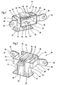
- the connector 10 shown in Fig. 1 to 3 comprises a housing 12, made up of two substantially cuboid and oriented perpendicular to each other Housing sections composed, each a socket section 14, 16 for receiving a respective flat plug contact form. Due to the rectangular arrangement of the socket sections 14, 16 are also the respective plug-in directions for the inserted plug contacts oriented perpendicular to each other.
- each female portion 14, 16 has a seen in the respective insertion direction rectangular cross-section on and by each four side walls 20 - 26 of the housing 12 and a back wall limited. At her back wall opposite Side are the receiving spaces 18 each open. These openings form Insertion for Conssteckende in the female sections 14, 16 Plug contacts.
- Each bushing section 14, 16 of the housing 12 has an outer wall 20, an inner wall 22 and two narrow sides 24, 26.
- the socket sections 14, 16 are oriented to each other so that the outer walls 20 and the inner walls 22 of the two socket sections 14, 16 respectively adjacent to each other at right angles, while the narrow sides 24, 26 respectively lie in one plane.
- a portion of the outer wall 20 of the one bushing section 14, 16 each forms a rear wall for limiting the Receiving space 18 of the other socket portion 16, 14th
- each female section 14, 16 is a coding Indexing device 28 provided by an elongated recess is formed, which is in an edge region of the outer wall 20 in Plug-in direction extends.
- the indexers 28 provide a correct one Inserting plug contacts into the socket sections 14, 16 sure by having a correspondingly formed on the plug contact Index or coding nose interact when inserting the plug contact in the socket sections 14, 16 in the index device 28th intervenes.
- the first socket portion 14 On its inner wall 22, the first socket portion 14 has a locking device for a plug contact.
- This locking device consists of a latching opening 30, in which a corresponding trained latch of a plug contact can engage.
- the second Bushing section 16 has on its inner wall 22 a starting from the insertion opening of the female section 16 in the insertion direction extending elongated opening 32 into which a nose of a plug contact can intervene. Both the detent opening 30 and the opening 32nd are arranged centrally in the inner walls 22.
- each bushing section 14, 16 Furthermore, a drogue 34 for the plug contact.
- the drogue 34 are interconnected continuations of the side walls 20th - 26 of the housing 12 is formed, which are each angled to the outside. The drogue 34 facilitate the insertion of plug contacts in the Socket sections 14, 16.
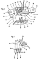
- each socket section 14 16 contact spring arms 36 arranged through the two in the Socket sections 14, 16 inserted plug contacts electrically with each other are connectable.
- the contact spring arms 36 are made of a metal material produced.
- Each contact spring arm 36 has an extending in the insertion direction Main section 38 on. After the arrangement of the contact spring arms 36 in the female sections 14, 16 become the main sections 38 two right-angled adjacent contact spring arms 36 at her rear end each electrically connected, e.g. together soldered.
- each contact section 40 connects to the insertion opening facing end of each main section 38th in each case.
- the contact sections 40 are bent back and form with the respective adjacent main sections 38 an angle in the range of about 30 to 60 °.
- the free Ends of the contact portions 40 are in turn once again in the direction the respective adjacent main sections 38 bent.
- the in the area the free ends of the contact portions 40 located bending of the contact portions 40 forms a contact zone 42 in which the contact spring arms 36 with corresponding contact surfaces of a plug-in contact of an electrical Line or directly to the tracks of the electrical line can get in touch.
- the outer walls 20 of the female sections 14, 16 each have one Survey 44.
- these surveys 44 are in the insertion direction extending channels 46 for receiving a respective main section 38 a contact spring arm 36 is provided.
- the contact spring arms 36 are embedded in the channels 46 such that the main sections 38 are not protrude beyond the outer wall 20 in the receiving space 18, but only the contact portions 40 and in particular the contact zones 42 protrude into the receiving space 18.
- the projection 48 is part of a Limiting device, which a tilting and / or displacement of the housing 12 limited. The limiting device will continue below described in more detail.
- each arm 50th has a perpendicular to the housing 12th adjacent shorter inner portion 52, one parallel to the housing 12 extending longer center section 54 and a this subsequent, perpendicular to the housing 12 facing away outer section 56 on.
- the flexible arms 50 are strip-shaped, wherein the strip plane oriented perpendicular to the insertion plane of the second socket portion 16 is.
- the middle portions 54 of the arms 50 thus extend parallel to the narrow sides 24, 26 of the second socket portion 16.
- the flexible arms 50 are formed integrally with the housing 12. in the illustrated embodiment, the entire connector 10 is a integrally formed injection molded part. The adjacent to the housing 12 Inner portions 52 of the flexible arms 50 are continuations of Rear wall of the second socket portion 16 and the outer wall 20 of the first female section 14.
- the holding device comprises two parallel and mutually spaced bolts 60, with their one end to a support 62, for example, on a door panel or a body panel, attached are.
- the bolts 60 are respectively provided with an axial threaded bore into which for mounting the Connector 10 on the holding device one through the through hole 58 of the flexible arms 50 passed screw 64th can intervene.
- the screw 64 for fastening the connector 10 only tightened so tight that the connector 10 while is secured to the holding device, the outer portions 56 of the flexible Arms 50 but freely with respect to the bolt 60 can pivot.
- sleeves in the through holes 58 of the flexible Insert arms 50 which surround the screws 64 and on which the flexible arms 50 are rotatably mounted.
- the flexible arms 50 can be the housing 12 of the holding device fastened connector 10 both in the insertion direction of the second socket portion 16 as well as transversely to it in the mating plane of the second socket section 16 shift (indicated by the arrow 68). additionally can the housing 12 because of the rotatable attachment of the flexible Arms 50 to the bolt 60 of the holding device in the insertion direction of the first sleeve portion 14 move (indicated by the arrow 70). In such a shift, the outer portions 56 both arms 50 pivoted in the same direction.
- the outer portion 56 of the one arm 50 in one direction and the outer portion of the other arm 50 in the other direction is twisted.
- the housing 12 is the 12th at a parallel to the direction of insertion of the second socket portion 16 Axis tilted.
- the flexible arms 50 also allow a tilting of the housing 12 by one in the mating plane of the second Socket section lying and transverse to the direction of insertion of the second Bushing section 16 extending axis and one to the mating plane the second socket portion 16 vertical axis.
- Components of this limiting device are the one Bolt 60 of the holding device, which is a displacement of the housing 12 transversely to the direction of insertion and in the mating plane of the second socket section 16 limit.
- the restriction means comprises in addition, two elongate protrusions 72 arranged on the carrier 62 are.
- the projections 72 extend parallel to the insertion plane of the second Socket portion 16 and are spaced from each other and in particular, As shown in Fig. 6, arranged above and below the bolt 60.
- the projections 72 form an upper and a lower stop for the arranged on the back of the first socket portion 14 Projection 48 and thus limit tilting of the housing 12 to one of the plug directions of the female sections 14, 16th vertical axis and / or a displacement of the housing 12 in the insertion direction the first socket portion 14 (arrow 70).
- the multiple angled training and pivotal storage of strip-shaped arms 50 provide for a particularly movable holder of the housing 12. Together with the drogue 34 this has the Advantage that plug contacts from a variety of directions and locations can be inserted into the socket sections 12, 14. So it is suitable the connector is particularly good for a "blind" mounting of electrical wiring, where a fitter can see the connector is locked and at least one plug contact blind in one Bushing section must be introduced.
- a connector 10, as in connection with FIG. 5 already described, attached to a holding device attached to a Carrier 62 is formed.
- the carrier 62 may be, for example to act a door panel or a body panel of a motor vehicle.
- a plug contact 74 of a first flat electrical line 76 in introduced the first socket portion 14 of the connector 10.
- the plug contact 74 is parallel to the first electrical Line 76 oriented. Because the mating plane of the first socket section 14 at least in the region of the connector 10 parallel to Surface of the carrier 62 extends, is also the plug contact 74 and Thus, the electrical line 76 is oriented parallel to the support surface 62. The electrical line 76 can therefore be well on the carrier if necessary 62 fix.
- a plug contact 78 of a second flat electrical Line 80 on a counter element 82 for example, a door module or an interior trim, attached.
- Fig. 8 shows that the plug contact 78 perpendicular to the electrical line 80 is oriented, i. the line 80 is seen in a plug-in direction rear portion of the plug contact 78 led laterally out of this.
- the plug contact 78 is pushed onto the base plate 84, wherein the guide elements of the plug contact 78 engage in the guides 86 of the base plate 84 and the latching hook 92 of the plug contact 78 in the latching opening 88 of the Base plate 84 engages.
- a correct insertion of the second plug contact 78 in the second Socket section 16 is ensured by the fact that the base plate 84th and thus the second plug contact 78 just so on the counter element 82nd are positioned such that an alignment of the counter-element 82 relative to Carrier 62 at the same time a correct orientation of the second plug contact 78 with respect to the second sleeve portion 16 causes.
- tolerances during assembly of the counter element 82 on the carrier 62, in the area can be up to a few millimeters and the subsequent one Misalignment of the second plug contact 78 with respect to the second Socket portion 16 are characterized by the floating storage, i.e. balanced the mobility of the connector housing 12, so that even one with respect to the regular thru axis shifted or tilted plug contact 78 securely in the second socket portion 16th can be picked up and contacted, as shown in Fig. 6 and 9 is.
- FIGS. 10A to C show a second embodiment of the invention Connector.
- the connector 94 includes like the first Embodiment, a housing 96. However, the housing 96 according to the second embodiment only a single socket section 98 on. This one female section 98 corresponds in shape and Function substantially the second socket portion 16 of the connector the first embodiment.
- the same reference numerals used as in the first embodiment Unless specifically otherwise, the components of the second embodiment are correct in shape and function with the components of the first embodiment match, which are provided with the same reference numerals.
- the female portion 98 of the housing 96 has a cuboid Basic shape and serves to receive a flat plug contact. Of the Receiving space 18 for the plug contact is through an upper outer wall 20, a lower outer wall 22, two narrow sides 24, 26 and a rear wall 100 limited. The rear wall 100 opposite is a Insertion opening for the plug contact, in the area of a drogue 34 is provided for the plug contact.
- a flexible arm 50 with a perpendicular to the housing 96th adjacent shorter inner portion 52, one parallel to the housing 96 extending longer center section 54 and a this subsequent, perpendicular to the housing 96 facing away outer section 56 provided.
- the flexible arms 50 are strip-shaped formed, wherein the strip plane perpendicular to the insertion plane of the Socket section 98 is oriented.
- the entire connector 94 is a integrally formed injection molded part, so that the to the housing 12th adjacent inner portions 52 of the flexible arms 50 continuations the rear wall 100 of the female portion 98 are.
- each clip pin 102 is provided, which in Plug-in direction extends.
- Each clip pin 102 is substantially separated by two semi-cylindrical pin half elements 104 formed by a axial gap are separated from each other.
- the pin half elements 104 have a certain elasticity and can be at their free ends Squeeze. At the free ends of the pin half elements 104 is in each case a hook-like projection 106 is formed.
- the pin half elements 104 together form a round cross-section the clip pin 102, so that the clip pin 102 in the receiving openings can rotate the holding device. This is how it works This embodiment, the pivotability of the flexible arms 50th achieved relative to the holding device.
- Fig. 11 shows contact spring arms 110, which are for an arrangement in the connector 94 are provided.
- the contact spring arms 110 each have a - extending in the assembled state in the plug-in direction - Main section 38, to which a multiply bent contact section 40 connects, which defines a contact zone 42, as already in Connection with Fig. 4 has been described.
- a crimping section 112 provided at the contact section 40 facing away from each contact spring arm 110. With the help of the crimping sections 112, the individual can be Contact spring arms 110 with respective tracks of an electrical Connect line 76.
- each contact spring arm 110 has a bent Latching tab 114, which is used to lock the Mixfederarms 110 in the housing 96 in one in the collection 44 of the housing 96 accordingly provided latching opening 116 engages.
- the contact spring arms 112 to the tracks of a crimped first electrical line 76 and from the back in the female portion 98 of the connector 94 is inserted.
- the thus prepared connector 94 by means of the clip pin 102 attached to a holding device, for example, on a Door or body panel of a motor vehicle can be provided.
- the electrical line 76 forms with the contact spring arms 112 in the Substantially right angles, so that they are at least in the area of the holding device parallel to the surface of the door or body panel runs and is easily fixable on the surface if necessary.
- a plug contact 78 of a second electrical Line 80 is pushed onto a base plate 84 (FIG. 12), such as already explained in connection with FIGS. 7 and 8.
- the Base plate 84 may be on a door module or interior trim, for example be glued to a motor vehicle.
- the base plate 84 is so on the door module or the inner panel positioned that when mounting the door module to the door or the interior trim on the body panel along with the orientation the door module or the inner lining with respect to the door or the Body at the same time an orientation of the plug contact 78 relative to Connector 94 is done.
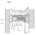
- Fig. 13 shows a connector 94 with inserted plug contact 78th in a final assembly state in which the connector 94 and the Plug contact 78 concealed between a carrier 62, e.g. Door or body panel, and a mating member 82, e.g. Door module or interior lining, are arranged.
- a carrier 62 e.g. Door or body panel
- a mating member 82 e.g. Door module or interior lining
Landscapes
- Details Of Connecting Devices For Male And Female Coupling (AREA)
- Coupling Device And Connection With Printed Circuit (AREA)
- Connector Housings Or Holding Contact Members (AREA)
Claims (14)
- Connecteur à fiche électrique (10, 94) avec un boítier (12, 96) présentant au moins une section de douille (14, 16, 98) pour loger un contact à fiche (74, 78) et deux bras flexibles (50) en vue de fixer le boítier (12, 96) à un dispositif support (60), les bras flexibles (50) permettant aussi bien de basculer que de déplacer le boítier (12, 96) dans les trois directions spatiales par rapport au dispositif support (60), chaque bras (50) présentant une section extérieure (56) s'étendant en saillie par rapport au boítier (12, 96), caractérisé en ce que la section extérieure respective peut être fixée de manière pivotante au dispositif support (60), de sorte que la section extérieure (56) peut pivoter autour d'un axe de pivotement parallèle au sens de connexion par rapport au dispositif support (60).
- Connecteur à fiche (10, 94) selon la revendication 1, caractérisé en ce que chaque bras (50) présente un alésage (58) ou une cheville clip (102) pour monter le boítier (12, 96) sur le dispositif support (60).
- Connecteur à fiche (10, 94) selon la revendication 1 ou 2, caractérisé en ce que les bras (50) sont conçus en forme de bande et orientés perpendiculairement à un niveau de connexion de la section de douille (16, 98), la largeur de la bande correspondant essentiellement à la largeur d'un petit côté (24, 26) de la section de douille.
- Connecteur à fiche (10, 94) selon l'une quelconque des revendications précédentes, caractérisé en ce que chaque bras (50) est coudé plusieurs fois et de préférence à angle droit.
- Connecteur à fiche (10, 94) selon l'une quelconque des revendications précédentes, caractérisé en ce que chaque bras (50) est coudé deux fois et respectivement en sens opposé, de sorte que chaque bras (50) présente une section intérieure (52) adjacente essentiellement perpendiculairement au boítier (12, 96), une section médiane (54) s'étendant essentiellement parallèlement au boítier (12, 96), et une section extérieure (56) s'étendant en saillie essentiellement perpendiculairement du boítier (12, 96).
- Connecteur à fiche (10, 94) selon l'une quelconque des revendications précédentes, caractérisé en ce qu'un entonnoir d'écoulement (34) est prévu pour un contact à fiche (74, 78) dans la zone d'une ouverture d'insertion de la section de douille (14, 16, 98).
- Connecteur à fiche (10) selon l'une quelconque des revendications précédentes, caractérisé en ce que le boítier présente deux sections de douille (14, 16), orientées à angle droit l'une à l'autre.
- Connecteur à fiche (10, 94) selon l'une quelconque des revendications précédentes, caractérisé en ce que des contacts métalliques (36), notamment des bras de ressort de contact, sont disposés dans chaque section de douille (14, 16, 98), afin d'établir un contact électrique d'un contact à fiche (74, 78) inséré dans la section de douille (14, 16, 98).
- Connecteur à fiche (10, 94) selon la revendication 8, caractérisé en ce que chaque contact (36) présente une section principale (38) à laquelle se raccorde une section de contact (40) courbée plusieurs fois.
- Connecteur à fiche (10, 94) selon l'une des revendications précédentes, caractérisé en ce qu'on prévoit un dispositif de limitation (48, 72, 60 ; 72, 108) pour limiter le déplacement et/ou le basculement du boítier (12, 96).
- Connecteur à fiche (10, 94) selon l'une quelconque des revendications précédentes, caractérisé en ce que le dispositif support présente deux boulons de fixation (60) orientés parallèlement et à écart l'un de l'autre ainsi que, facultativement, deux avancées (72) s'étendant transversalement aux boulons, lesquelles avancées limitent un déplacement et/ou un basculement du boítier (12, 96).
- Procédé pour raccorder électriquement une première ligne électrique (76) à une deuxième ligne électrique (80), selon lequel un connecteur à fiche électrique (10, 94) selon l'une quelconque des revendications précédentes, est raccordé à une première ligne électrique (76), le connecteur à fiche (10, 94) est fixé au moyen du dispositif support (60) à un support (62) pour un contre-élément (82), un contact à fiche (78) de la deuxième ligne électrique (80) est fixé au contre-élément (82), et le contre-élément (82) est monté sur le support (62), le contact à fiche (78) de la deuxième ligne électrique (80) étant orienté simultanément à l'orientation du contre-élément (82) par rapport au support (62) relativement au connecteur à fiche (10, 94), et étant inséré dans une section de douille (16, 98) du connecteur à fiche (10, 94) lors de la fixation du contre-élément (82) au support (62).
- Procédé selon la revendication 12, caractérisé en ce qu'un contact à fiche (74) de la première ligne électrique (76) est enfiché dans une autre section de douille (14) du connecteur à fiche (10) afin de raccorder le connecteur à fiche (10) à la première ligne électrique (76).
- Procédé selon la revendication 12 ou 13, caractérisé en ce que le connecteur à fiche (10, 94) est fixé à une portière de véhicule ou à une carrosserie et que le contact à fiche (78) de la deuxième ligne électrique (80) est fixé à un module de portière ou à un revêtement intérieur.
Applications Claiming Priority (2)
| Application Number | Priority Date | Filing Date | Title |
|---|---|---|---|
| GBGB0302890.9A GB0302890D0 (en) | 2003-02-10 | 2003-02-10 | Two-part electrical connector |
| GB0302890 | 2003-02-10 |
Publications (2)
| Publication Number | Publication Date |
|---|---|
| EP1445840A1 EP1445840A1 (fr) | 2004-08-11 |
| EP1445840B1 true EP1445840B1 (fr) | 2005-08-24 |
Family
ID=9952662
Family Applications (1)
| Application Number | Title | Priority Date | Filing Date |
|---|---|---|---|
| EP03010514A Expired - Lifetime EP1445840B1 (fr) | 2003-02-10 | 2003-05-09 | Connecteur Electrique |
Country Status (4)
| Country | Link |
|---|---|
| EP (1) | EP1445840B1 (fr) |
| AT (1) | ATE303006T1 (fr) |
| DE (1) | DE50301038D1 (fr) |
| GB (1) | GB0302890D0 (fr) |
Families Citing this family (7)
| Publication number | Priority date | Publication date | Assignee | Title |
|---|---|---|---|---|
| EP1930990B1 (fr) * | 2006-12-07 | 2016-04-27 | Delphi Technologies, Inc. | Connexion enfichable électrique |
| FR2940862B1 (fr) * | 2009-01-05 | 2012-12-14 | Peugeot Citroen Automobiles Sa | Connecteur equipe de moyens de fixation |
| CN102790329B (zh) * | 2011-05-16 | 2015-12-09 | 富士康(昆山)电脑接插件有限公司 | 电连接器及其组装方法 |
| DE102016009225B4 (de) * | 2016-07-28 | 2021-11-04 | e.solutions GmbH | Steckerelement, Steckersystem, Fahrzeug-Halterung und Fahrzeug |
| DE102018132142B4 (de) * | 2018-12-13 | 2020-07-02 | Phoenix Contact Gmbh & Co. Kg | Steckverbinderanordnung zur Kontaktierung in mehreren Raumrichtungen |
| CN112909651B (zh) * | 2021-03-08 | 2025-12-16 | 中航光电科技股份有限公司 | 一种连接器、外接插座以及印制板插座 |
| EP4407813A1 (fr) * | 2023-01-26 | 2024-07-31 | Volvo Car Corporation | Support de connecteur pour un ensemble de connexion électrique pour un faisceau de câbles d'un véhicule |
Family Cites Families (6)
| Publication number | Priority date | Publication date | Assignee | Title |
|---|---|---|---|---|
| US5199892A (en) * | 1991-10-15 | 1993-04-06 | International Business Machines Corporation | Connector assembly and information handling system component utilizing same |
| US5383790A (en) * | 1993-11-19 | 1995-01-24 | G & H Technology, Inc. | Connector with floating self-alignment and zero impulse separation mechanisms |
| EP0907223A3 (fr) * | 1997-10-03 | 2001-02-07 | Lear Automotive Dearborn, Inc. | Connecteur électrique à alignement automatique |
| DE19804453A1 (de) * | 1998-02-05 | 1999-08-12 | Itt Mfg Enterprises Inc | Schwimmend gelagerter Verbinder zum Verbinden elektrischer Baugruppen |
| US6234817B1 (en) * | 1999-04-29 | 2001-05-22 | Hon Hai Precision Ind. Co., Ltd. | Blind-mate, floatable connectors assembly |
| IT1320513B1 (it) * | 2000-06-20 | 2003-12-10 | Framatome Connectors Italia | Connettore elettrico. |
-
2003
- 2003-02-10 GB GBGB0302890.9A patent/GB0302890D0/en not_active Ceased
- 2003-05-09 AT AT03010514T patent/ATE303006T1/de not_active IP Right Cessation
- 2003-05-09 DE DE50301038T patent/DE50301038D1/de not_active Expired - Fee Related
- 2003-05-09 EP EP03010514A patent/EP1445840B1/fr not_active Expired - Lifetime
Also Published As
| Publication number | Publication date |
|---|---|
| ATE303006T1 (de) | 2005-09-15 |
| GB0302890D0 (en) | 2003-03-12 |
| DE50301038D1 (de) | 2005-09-29 |
| EP1445840A1 (fr) | 2004-08-11 |
Similar Documents
| Publication | Publication Date | Title |
|---|---|---|
| DE60027611T2 (de) | Kabelverbinder mit gesteuerter Impedanz | |
| DE112009000065B4 (de) | Kabelbaum | |
| DE10356469B4 (de) | Erdverbinder und Verfahren zum Montieren desselben | |
| DE69904095T2 (de) | Elektrischer Steckverbinder zur Herstellung des Kontakts mit mindestens einer flachen Leiterfolie | |
| DE102008038563B4 (de) | Verbinder | |
| DE8713038U1 (de) | Buchsenartiger elektrischer Anschluß | |
| DE69416079T2 (de) | Klemmverbinder | |
| DE4119685C2 (de) | Elektrische Steckverbindungsvorrichtung | |
| DE102014000955B4 (de) | Verbinder mit einer elektronischen Komponente, Halteeinrichtung und Herstellungsverfahren | |
| DE4016114C2 (de) | Elektrischer Mehrkontakt-Verbinder, der eine geringe Verbindungs- und Trennkraft erfordert | |
| DE102007006645A1 (de) | Elektrischer Steckverbinder | |
| EP2475057B2 (fr) | Dispositif de support de câble | |
| DE69013734T2 (de) | Elektrischer Verbinder. | |
| DE69708734T2 (de) | Abgeschirmter Verbinder, insbesondere mit Stecker und Ablagefläche zum Verbinden auf einer ebenen Unterlage | |
| DE10223271B4 (de) | Steckverbinder | |
| DE202019105625U1 (de) | Stromabgriffvorrichtung, Anordnung mit einem Stromführungsprofil und einer Stromabgriffvorrichtung | |
| EP1445840A1 (fr) | Connecteur Electrique | |
| EP4104253B1 (fr) | Ensemble de pièce de connecteur enfichable, pièce de connecteur enfichable et dispositif électronique | |
| EP0831561A2 (fr) | Assemblage de connecteurs électriques | |
| DE102024125089A1 (de) | Steckereinsatz | |
| WO2024125704A1 (fr) | Insert de connecteur à fiche pour un connecteur électrique à fiche | |
| DE60032856T2 (de) | Halter für modulare Verbinder, insbesondere für Verbinder mit Halbleiterplättchen sowie zusammengesetzter Verbinder | |
| DE202005007221U1 (de) | Befestigungseinsatz für einen Steckverbinder | |
| DE3827886C1 (en) | Contact element for an electrical plug connector | |
| EP1720222B1 (fr) | Connecteur électrique, notamment pour des systèmes d' allumage d' airbag |
Legal Events
| Date | Code | Title | Description |
|---|---|---|---|
| PUAI | Public reference made under article 153(3) epc to a published international application that has entered the european phase |
Free format text: ORIGINAL CODE: 0009012 |
|
| AK | Designated contracting states |
Kind code of ref document: A1 Designated state(s): AT BE BG CH CY CZ DE DK EE ES FI FR GB GR HU IE IT LI LU MC NL PT RO SE SI SK TR |
|
| AX | Request for extension of the european patent |
Extension state: AL LT LV MK |
|
| 17P | Request for examination filed |
Effective date: 20040901 |
|
| 17Q | First examination report despatched |
Effective date: 20040929 |
|
| GRAP | Despatch of communication of intention to grant a patent |
Free format text: ORIGINAL CODE: EPIDOSNIGR1 |
|
| AKX | Designation fees paid |
Designated state(s): AT BE BG CH CY CZ DE DK EE ES FI FR GB GR HU IE IT LI LU MC NL PT RO SE SI SK TR |
|
| GRAS | Grant fee paid |
Free format text: ORIGINAL CODE: EPIDOSNIGR3 |
|
| GRAA | (expected) grant |
Free format text: ORIGINAL CODE: 0009210 |
|
| AK | Designated contracting states |
Kind code of ref document: B1 Designated state(s): AT BE BG CH CY CZ DE DK EE ES FI FR GB GR HU IE IT LI LU MC NL PT RO SE SI SK TR |
|
| PG25 | Lapsed in a contracting state [announced via postgrant information from national office to epo] |
Ref country code: FI Free format text: LAPSE BECAUSE OF FAILURE TO SUBMIT A TRANSLATION OF THE DESCRIPTION OR TO PAY THE FEE WITHIN THE PRESCRIBED TIME-LIMIT Effective date: 20050824 Ref country code: RO Free format text: LAPSE BECAUSE OF FAILURE TO SUBMIT A TRANSLATION OF THE DESCRIPTION OR TO PAY THE FEE WITHIN THE PRESCRIBED TIME-LIMIT Effective date: 20050824 Ref country code: SI Free format text: LAPSE BECAUSE OF FAILURE TO SUBMIT A TRANSLATION OF THE DESCRIPTION OR TO PAY THE FEE WITHIN THE PRESCRIBED TIME-LIMIT Effective date: 20050824 Ref country code: SK Free format text: LAPSE BECAUSE OF FAILURE TO SUBMIT A TRANSLATION OF THE DESCRIPTION OR TO PAY THE FEE WITHIN THE PRESCRIBED TIME-LIMIT Effective date: 20050824 Ref country code: CZ Free format text: LAPSE BECAUSE OF FAILURE TO SUBMIT A TRANSLATION OF THE DESCRIPTION OR TO PAY THE FEE WITHIN THE PRESCRIBED TIME-LIMIT Effective date: 20050824 Ref country code: NL Free format text: LAPSE BECAUSE OF FAILURE TO SUBMIT A TRANSLATION OF THE DESCRIPTION OR TO PAY THE FEE WITHIN THE PRESCRIBED TIME-LIMIT Effective date: 20050824 Ref country code: IE Free format text: LAPSE BECAUSE OF FAILURE TO SUBMIT A TRANSLATION OF THE DESCRIPTION OR TO PAY THE FEE WITHIN THE PRESCRIBED TIME-LIMIT Effective date: 20050824 Ref country code: GB Free format text: LAPSE BECAUSE OF FAILURE TO SUBMIT A TRANSLATION OF THE DESCRIPTION OR TO PAY THE FEE WITHIN THE PRESCRIBED TIME-LIMIT Effective date: 20050824 |
|
| REG | Reference to a national code |
Ref country code: GB Ref legal event code: FG4D Free format text: NOT ENGLISH |
|
| REG | Reference to a national code |
Ref country code: CH Ref legal event code: EP |
|
| REG | Reference to a national code |
Ref country code: IE Ref legal event code: FG4D Free format text: LANGUAGE OF EP DOCUMENT: GERMAN |
|
| REF | Corresponds to: |
Ref document number: 50301038 Country of ref document: DE Date of ref document: 20050929 Kind code of ref document: P |
|
| PG25 | Lapsed in a contracting state [announced via postgrant information from national office to epo] |
Ref country code: SE Free format text: LAPSE BECAUSE OF FAILURE TO SUBMIT A TRANSLATION OF THE DESCRIPTION OR TO PAY THE FEE WITHIN THE PRESCRIBED TIME-LIMIT Effective date: 20051124 Ref country code: GR Free format text: LAPSE BECAUSE OF FAILURE TO SUBMIT A TRANSLATION OF THE DESCRIPTION OR TO PAY THE FEE WITHIN THE PRESCRIBED TIME-LIMIT Effective date: 20051124 Ref country code: DK Free format text: LAPSE BECAUSE OF FAILURE TO SUBMIT A TRANSLATION OF THE DESCRIPTION OR TO PAY THE FEE WITHIN THE PRESCRIBED TIME-LIMIT Effective date: 20051124 Ref country code: BG Free format text: LAPSE BECAUSE OF FAILURE TO SUBMIT A TRANSLATION OF THE DESCRIPTION OR TO PAY THE FEE WITHIN THE PRESCRIBED TIME-LIMIT Effective date: 20051124 |
|
| PG25 | Lapsed in a contracting state [announced via postgrant information from national office to epo] |
Ref country code: ES Free format text: LAPSE BECAUSE OF FAILURE TO SUBMIT A TRANSLATION OF THE DESCRIPTION OR TO PAY THE FEE WITHIN THE PRESCRIBED TIME-LIMIT Effective date: 20051205 |
|
| PG25 | Lapsed in a contracting state [announced via postgrant information from national office to epo] |
Ref country code: PT Free format text: LAPSE BECAUSE OF FAILURE TO SUBMIT A TRANSLATION OF THE DESCRIPTION OR TO PAY THE FEE WITHIN THE PRESCRIBED TIME-LIMIT Effective date: 20060124 |
|
| NLV1 | Nl: lapsed or annulled due to failure to fulfill the requirements of art. 29p and 29m of the patents act | ||
| PG25 | Lapsed in a contracting state [announced via postgrant information from national office to epo] |
Ref country code: HU Free format text: LAPSE BECAUSE OF FAILURE TO SUBMIT A TRANSLATION OF THE DESCRIPTION OR TO PAY THE FEE WITHIN THE PRESCRIBED TIME-LIMIT Effective date: 20060225 |
|
| GBV | Gb: ep patent (uk) treated as always having been void in accordance with gb section 77(7)/1977 [no translation filed] |
Effective date: 20050824 |
|
| REG | Reference to a national code |
Ref country code: IE Ref legal event code: FD4D |
|
| ET | Fr: translation filed | ||
| PG25 | Lapsed in a contracting state [announced via postgrant information from national office to epo] |
Ref country code: AT Free format text: LAPSE BECAUSE OF NON-PAYMENT OF DUE FEES Effective date: 20060509 |
|
| PG25 | Lapsed in a contracting state [announced via postgrant information from national office to epo] |
Ref country code: BE Free format text: LAPSE BECAUSE OF NON-PAYMENT OF DUE FEES Effective date: 20060531 Ref country code: MC Free format text: LAPSE BECAUSE OF NON-PAYMENT OF DUE FEES Effective date: 20060531 |
|
| PLBE | No opposition filed within time limit |
Free format text: ORIGINAL CODE: 0009261 |
|
| STAA | Information on the status of an ep patent application or granted ep patent |
Free format text: STATUS: NO OPPOSITION FILED WITHIN TIME LIMIT |
|
| 26N | No opposition filed |
Effective date: 20060526 |
|
| PGFP | Annual fee paid to national office [announced via postgrant information from national office to epo] |
Ref country code: DE Payment date: 20070503 Year of fee payment: 5 |
|
| BERE | Be: lapsed |
Owner name: DELPHI TECHNOLOGIES, INC. Effective date: 20060531 |
|
| PGFP | Annual fee paid to national office [announced via postgrant information from national office to epo] |
Ref country code: IT Payment date: 20070507 Year of fee payment: 5 |
|
| REG | Reference to a national code |
Ref country code: CH Ref legal event code: PL |
|
| PG25 | Lapsed in a contracting state [announced via postgrant information from national office to epo] |
Ref country code: CH Free format text: LAPSE BECAUSE OF NON-PAYMENT OF DUE FEES Effective date: 20070531 Ref country code: LI Free format text: LAPSE BECAUSE OF NON-PAYMENT OF DUE FEES Effective date: 20070531 |
|
| PGFP | Annual fee paid to national office [announced via postgrant information from national office to epo] |
Ref country code: FR Payment date: 20070510 Year of fee payment: 5 |
|
| PG25 | Lapsed in a contracting state [announced via postgrant information from national office to epo] |
Ref country code: EE Free format text: LAPSE BECAUSE OF FAILURE TO SUBMIT A TRANSLATION OF THE DESCRIPTION OR TO PAY THE FEE WITHIN THE PRESCRIBED TIME-LIMIT Effective date: 20050824 |
|
| PG25 | Lapsed in a contracting state [announced via postgrant information from national office to epo] |
Ref country code: LU Free format text: LAPSE BECAUSE OF NON-PAYMENT OF DUE FEES Effective date: 20060509 Ref country code: TR Free format text: LAPSE BECAUSE OF FAILURE TO SUBMIT A TRANSLATION OF THE DESCRIPTION OR TO PAY THE FEE WITHIN THE PRESCRIBED TIME-LIMIT Effective date: 20050824 |
|
| PG25 | Lapsed in a contracting state [announced via postgrant information from national office to epo] |
Ref country code: CY Free format text: LAPSE BECAUSE OF FAILURE TO SUBMIT A TRANSLATION OF THE DESCRIPTION OR TO PAY THE FEE WITHIN THE PRESCRIBED TIME-LIMIT Effective date: 20050824 |
|
| REG | Reference to a national code |
Ref country code: FR Ref legal event code: ST Effective date: 20090119 |
|
| PG25 | Lapsed in a contracting state [announced via postgrant information from national office to epo] |
Ref country code: FR Free format text: LAPSE BECAUSE OF NON-PAYMENT OF DUE FEES Effective date: 20080602 Ref country code: DE Free format text: LAPSE BECAUSE OF NON-PAYMENT OF DUE FEES Effective date: 20081202 |
|
| PG25 | Lapsed in a contracting state [announced via postgrant information from national office to epo] |
Ref country code: IT Free format text: LAPSE BECAUSE OF NON-PAYMENT OF DUE FEES Effective date: 20080509 |