EP4104253B1 - Ensemble de pièce de connecteur enfichable, pièce de connecteur enfichable et dispositif électronique - Google Patents
Ensemble de pièce de connecteur enfichable, pièce de connecteur enfichable et dispositif électronique Download PDFInfo
- Publication number
- EP4104253B1 EP4104253B1 EP21704519.4A EP21704519A EP4104253B1 EP 4104253 B1 EP4104253 B1 EP 4104253B1 EP 21704519 A EP21704519 A EP 21704519A EP 4104253 B1 EP4104253 B1 EP 4104253B1
- Authority
- EP
- European Patent Office
- Prior art keywords
- assembly
- holding frame
- housing part
- locking element
- locking
- Prior art date
- Legal status (The legal status is an assumption and is not a legal conclusion. Google has not performed a legal analysis and makes no representation as to the accuracy of the status listed.)
- Active
Links
Images



Classifications
-
- H—ELECTRICITY
- H01—ELECTRIC ELEMENTS
- H01R—ELECTRICALLY-CONDUCTIVE CONNECTIONS; STRUCTURAL ASSOCIATIONS OF A PLURALITY OF MUTUALLY-INSULATED ELECTRICAL CONNECTING ELEMENTS; COUPLING DEVICES; CURRENT COLLECTORS
- H01R13/00—Details of coupling devices of the kinds covered by groups H01R12/70 or H01R24/00 - H01R33/00
- H01R13/46—Bases; Cases
- H01R13/516—Means for holding or embracing insulating body, e.g. casing, hoods
- H01R13/518—Means for holding or embracing insulating body, e.g. casing, hoods for holding or embracing several coupling parts, e.g. frames
-
- H—ELECTRICITY
- H01—ELECTRIC ELEMENTS
- H01R—ELECTRICALLY-CONDUCTIVE CONNECTIONS; STRUCTURAL ASSOCIATIONS OF A PLURALITY OF MUTUALLY-INSULATED ELECTRICAL CONNECTING ELEMENTS; COUPLING DEVICES; CURRENT COLLECTORS
- H01R13/00—Details of coupling devices of the kinds covered by groups H01R12/70 or H01R24/00 - H01R33/00
- H01R13/46—Bases; Cases
- H01R13/502—Bases; Cases composed of different pieces
- H01R13/506—Bases; Cases composed of different pieces assembled by snap action of the parts
-
- H—ELECTRICITY
- H01—ELECTRIC ELEMENTS
- H01R—ELECTRICALLY-CONDUCTIVE CONNECTIONS; STRUCTURAL ASSOCIATIONS OF A PLURALITY OF MUTUALLY-INSULATED ELECTRICAL CONNECTING ELEMENTS; COUPLING DEVICES; CURRENT COLLECTORS
- H01R13/00—Details of coupling devices of the kinds covered by groups H01R12/70 or H01R24/00 - H01R33/00
- H01R13/46—Bases; Cases
- H01R13/502—Bases; Cases composed of different pieces
- H01R13/508—Bases; Cases composed of different pieces assembled by a separate clip or spring
-
- H—ELECTRICITY
- H01—ELECTRIC ELEMENTS
- H01R—ELECTRICALLY-CONDUCTIVE CONNECTIONS; STRUCTURAL ASSOCIATIONS OF A PLURALITY OF MUTUALLY-INSULATED ELECTRICAL CONNECTING ELEMENTS; COUPLING DEVICES; CURRENT COLLECTORS
- H01R13/00—Details of coupling devices of the kinds covered by groups H01R12/70 or H01R24/00 - H01R33/00
- H01R13/62—Means for facilitating engagement or disengagement of coupling parts or for holding them in engagement
- H01R13/639—Additional means for holding or locking coupling parts together, after engagement, e.g. separate keylock, retainer strap
-
- H—ELECTRICITY
- H01—ELECTRIC ELEMENTS
- H01R—ELECTRICALLY-CONDUCTIVE CONNECTIONS; STRUCTURAL ASSOCIATIONS OF A PLURALITY OF MUTUALLY-INSULATED ELECTRICAL CONNECTING ELEMENTS; COUPLING DEVICES; CURRENT COLLECTORS
- H01R13/00—Details of coupling devices of the kinds covered by groups H01R12/70 or H01R24/00 - H01R33/00
- H01R13/02—Contact members
- H01R13/22—Contacts for co-operating by abutting
- H01R13/24—Contacts for co-operating by abutting resilient; resiliently-mounted
- H01R13/2407—Contacts for co-operating by abutting resilient; resiliently-mounted characterized by the resilient means
- H01R13/2428—Contacts for co-operating by abutting resilient; resiliently-mounted characterized by the resilient means using meander springs
-
- H—ELECTRICITY
- H01—ELECTRIC ELEMENTS
- H01R—ELECTRICALLY-CONDUCTIVE CONNECTIONS; STRUCTURAL ASSOCIATIONS OF A PLURALITY OF MUTUALLY-INSULATED ELECTRICAL CONNECTING ELEMENTS; COUPLING DEVICES; CURRENT COLLECTORS
- H01R13/00—Details of coupling devices of the kinds covered by groups H01R12/70 or H01R24/00 - H01R33/00
- H01R13/648—Protective earth or shield arrangements on coupling devices, e.g. anti-static shielding
- H01R13/655—Protective earth or shield arrangements on coupling devices, e.g. anti-static shielding with earth brace
-
- H—ELECTRICITY
- H01—ELECTRIC ELEMENTS
- H01R—ELECTRICALLY-CONDUCTIVE CONNECTIONS; STRUCTURAL ASSOCIATIONS OF A PLURALITY OF MUTUALLY-INSULATED ELECTRICAL CONNECTING ELEMENTS; COUPLING DEVICES; CURRENT COLLECTORS
- H01R13/00—Details of coupling devices of the kinds covered by groups H01R12/70 or H01R24/00 - H01R33/00
- H01R13/73—Means for mounting coupling parts to apparatus or structures, e.g. to a wall
- H01R13/74—Means for mounting coupling parts in openings of a panel
- H01R13/741—Means for mounting coupling parts in openings of a panel using snap fastening means
Definitions
- the invention relates to an assembly of a connector part. Furthermore, the invention relates to such a connector part and an electronic device.
- Retaining frames of such assemblies serve for the modular use and retention of contact inserts on connector parts.
- One or more contact inserts can be arranged on such a retaining frame to be inserted, together with the retaining frame, into a housing or into a housing part of the housing of a connector part and connected to the housing or the housing part. In this way, contact inserts can be combined with one another in a modular manner and arranged in or on a connector part via the retaining frame.
- Such contact inserts can, for example, have one or more electrical contacts.
- the contact inserts are connected to electrical wires fed into a connector and, on the other hand, form plug contacts through which the connector can be plugged into a mating connector part for electrical contact.
- Such modular contact inserts offer the advantage of flexible combination and thus variable application of connectors.
- a second holding frame part can be attached to a first holding frame part, which has recesses for receiving projection elements of the contact inserts, in order to block projection elements lying in the recesses and thus to lock them to the holding frame.
- a mounting frame on which a contact insert is arranged can be inserted for fixation into a receiving opening of a device housing.
- the mounting frame consists at least partially of an electrically conductive material in order to establish an electrically conductive connection between the contact insert and the device housing.
- the mounting frame is locked to the device housing via a plurality of locking elements.
- a retaining frame for accommodating modular contact inserts is often screwed to a housing part into which the retaining frame is to be inserted. While this ensures a mechanically strong, reliably durable connection, it requires a comparatively complex assembly process because, in order to connect the retaining frame to an associated housing part, the retaining frame must first be inserted into the housing part and then screwed to the housing part.
- the invention is based on the object of providing an assembly, a connector part and an electronic device in which the connection of a holding frame to a housing part can be simplified.
- the assembly according to the invention comprises a holding frame which has a receiving space for receiving at least one contact insert and which has at least one flange section.
- the assembly further comprises a housing part which has a receiving opening into which the holding frame can be inserted in an insertion direction, and the housing part has at least one support section formed in the receiving opening.
- at least one locking element is provided which is arranged on the holding frame, wherein the locking element engages with the housing part in an inserted position in order to lock the holding frame to the housing part.
- at least one spring element is provided which is arranged on the at least one flange section and which, in the inserted position, rests on the at least one support section to form an electrical contact between the holding frame and the housing part and is transferred into a tensioned state.
- At least one spring element is now provided for the mechanical and electrical connection of the holding frame to the housing part, thus eliminating the need for a screw connection.
- the spring element is characterized by elastic behavior.
- the spring element is preferably made of an electrically conductive material, such as a metal. formed.
- the locking element can be designed in such a way that when the holding frame is inserted into the receiving opening of the housing part, the locking between the holding frame and the housing part is established automatically.
- a non-automatic locking but rather a manual locking, for example, is also possible.
- a secure, reliable connection can be created between the holding frame and the housing part, which can be easily released by unlocking the locking element.
- the production of screw connections can thus be eliminated, so that the connection between the holding frame and the housing part can be established in a simple manner.
- the holding frame is inserted into the receiving opening of the housing part along an insertion direction, so that the holding frame, with the at least one spring element arranged on the at least one flange section, can come into contact with one or more support sections of the housing part.
- the holding frame thus rests on the one or more support sections, so that the holding frame, viewed axially along the insertion direction, can reach a defined position within the housing part.
- the housing part can be made of a metal, so that the housing part can be, for example, a zinc die-cast part or an aluminum die-cast part.
- the housing part can also be made only partially of a metal and partially of a plastic material, in which case a metal material is provided, in particular in the region of the at least one support section, which metal material, in the inserted position, makes electrical contact with the spring element resting on the support section and arranged on the flange section of the holding frame. Due to the tensioned state of the spring element in this contacting position with the support section, a secure contact between the holding frame and the housing part can be formed at any time, since the spring element compensates for relative movements between the housing part and the holding frame in the inserted position. can be.
- the mechanical locking of the holding frame to the housing part can also be improved via the at least one spring element, since the clamping force of the at least one spring element can bring the locking element into particularly secure engagement with the housing part, in particular by pressing it.
- the holding frame preferably has two flange sections, with two spring elements and one locking element preferably being arranged on each flange section, the housing part then having four support sections, on each of which one of the four spring elements rests in the inserted position.
- the spring element preferably has a free end section which, in a relaxed state of the spring element, can extend at an angle of 10° ⁇ ⁇ ⁇ 40° to the flange section of the holding frame.
- the free end section of the spring element can thus extend, in a relaxed and thus in the non-tensioned state, at an angle to the flange section to which the spring element is arranged or fastened. Due to this angular arrangement of the free end section of the spring element, the spring element can be tensioned when the holding frame is inserted into the housing part and thus when the spring element hits the support section of the housing part.
- the free end section of the spring element is preferably aligned parallel to the flange section of the holding frame.
- the free end section can be designed in the form of a spring tab or a leg.
- the free end section can be connected to a fastening section of the spring element, wherein the spring element can be held and fastened to the flange section of the holding frame via its fastening section.
- the fastening section can, for example, be U-shaped, so that the spring element can engage around the flange section of the holding frame with its fastening section. Both the free end section and the fastening section are preferably flat.
- the spring element can be bent in an S-shape.
- the free end section can form an S-shape together with the fastening section. Due to the S-shape, a compact design of the spring element with good spring properties is possible.
- the spring element can be a stamped and bent part, which allows for cost-reduced production.
- the spring element can be punched from a sheet metal strip and bent into the desired shape, in particular to form the free end section and the fastening section.
- the spring element is made of a spring-elastic, electrically conductive material.
- the spring element can be attached to the flange section by means of a snap-in connection.
- a snap-in tab or locking lug can be formed on the spring element, which can engage in a recess or opening formed in the flange section.
- the snap-in tab or locking lug can be formed on the fastening section of the spring element.
- At least one recess is preferably formed on the housing part, into which the locking element can engage at least partially in the inserted position.
- the locking element can engage in a form-fitting manner with at least a partial region of the locking element.
- the locking element can automatically snap into the recess of the housing part, whereby a latching connection can be formed between the holding frame and the housing part.
- the number of recesses on the housing part preferably corresponds to the number of locking elements, so that each locking element can be assigned a recess.
- the one or more recesses are preferably formed on one or both end walls of the housing part, wherein the recesses are formed on the inner surfaces of the end walls facing towards the receiving opening.
- the recesses can each be trough-shaped.
- the locking element is preferably designed such that it can be disengaged from the housing part in order to release the locking of the holding frame with the housing part. This can preferably be done with the aid of a tool, such as a screwdriver.
- the locking element can have a tool receiving area into which the tool can engage in order to transfer the locking element from a locked position to an unlocked position.
- the tool receiving area is preferably formed centrally along the length of the locking element.
- the tool receiving area can have a free space into which the tool can engage.
- the tool receiving area can be in the form of a tab formed or molded onto the locking element.
- the locking element prefferably be formed from a sheet metal strip.
- the locking element then preferably has a flat design, at least in some areas.
- the locking element is formed from a displaceably mounted latching element and an actuating lever, wherein the latching element can be moved into a locked position and into an unlocked position by means of the actuating lever.
- the latching element is preferably displaceably mounted transversely to the direction of insertion of the holding frame into the housing part in order to be able to engage and disengage from the housing part.
- the actuating lever is preferably pivotably mounted in such a way that an axial or translational movement of the latching element occurs when the actuating lever is pivoted about a pivot axis.
- the at least one locking element and the at least one spring element can be formed from separate components.
- the locking element and the spring element can then be arranged and mounted separately from one another on the holding frame, in particular on the flange section of the holding frame.
- two spring elements are assigned to each locking element, so that one locking element and two spring elements are arranged on each of the two flange sections of the holding frame.
- the at least one locking element and the at least one spring element can be formed as a single-piece component.
- the single-piece component then preferably forms a locking element and two spring elements, wherein this single-piece component can be arranged on the flange portion of the holding frame.
- Such a single-piece component can, for example, be punched and bent from a sheet metal strip.
- the locking element is arranged between two spring elements.
- the object of the invention is further achieved by means of a connector part of a connector, which has an assembly designed and further developed as described above and at least one contact insert inserted into the receiving space of the holding frame.
- the contact inserts can be inserted into the holding frame in a modular manner, so that the contact inserts can be combined with one another in any desired manner.
- the contact inserts can each have one or more contacts, so that the combination of the contact inserts can create a mating face to which an associated mating connector part can be attached in a corresponding manner to provide electrical contact.
- the object according to the invention is achieved by means of an electronic device which has at least one assembly described above, designed and further developed, and/or at least one connector part designed and further developed as described above.
- Fig. 1 shows a housing part 110, into which a housing such as in Fig. 3 shown holding frame 111 can be used to mount an assembly 100 as shown in Fig. 7 shown to train.
- Fig. 2 shows that in Fig. 1 shown housing part 110 in a sectional view along the Fig. 1 shown line AA.
- the housing part 110 has a receiving opening 112 into which the holding frame 111 can be inserted in an insertion direction E, so that in the inserted position, as shown for example in Fig. 7 As shown, the holding frame 111 is circumferentially enclosed by the housing part 110.
- the receiving opening 112 is delimited by two opposing end walls 113, 114 and two opposing longitudinal side walls 115, 116.
- the end walls 113, 114 are arranged at a right angle to the longitudinal side walls 115, 116.
- each support section 117 is connected to one of the end walls 113, 114 and to one of the longitudinal side walls 115, 116 of the housing part 110.
- the support sections 117 are formed, at least in regions, from an electrically conductive material, such as a metal, so that an electrical contact is established between the housing part 110 and the holding frame 111 via the support sections 117. can be formed. If the holding frame 111 is at a ground potential, the housing part 110 is also connected to the ground potential, whereby a PE contact can be formed.
- spring elements 118 are arranged on the holding frame 111, which are made of an electrically conductive material and rest on the support sections 117 when the holding frame 111 is inserted into the housing part 110. As shown in Fig. 3 As can be seen, four spring elements 118 are arranged on the holding frame 111, so that each support section 117 of the housing part 110 can be assigned a spring element 118.
- the holding frame 111 has two laterally formed flange sections 119, to which the spring elements 118 are held and fastened. Two spring elements 118 are arranged on each of the two flange sections 119. In the inserted position, the holding frame 111 rests with the spring elements 118 on the support sections 117 of the housing part 110.
- the spring element 118 is in Fig. 4 shown individually.
- the spring element 118 is designed here in the form of a stamped and bent part.
- the spring element 118 is punched from a sheet metal strip and bent into the desired shape.
- the spring element 118 has a fastening section 120 and a free end section 121 adjoining the fastening section 120.
- the fastening section 120, together with the free end section 121, is shaped or bent such that the spring element 118 has an S-shape.
- the spring element 118 is mounted and secured to the flange portion 119 of the holding frame 111 via the fastening portion 120.
- the fastening portion 120 is bent in a U-shape.
- the fastening portion 120 has a first leg 122 and a second leg 123, wherein the first leg 122 and the second leg 123 are connected to one another via an arcuate portion 124.
- the first leg 122 and the second leg 123 run substantially parallel to one another.
- the arcuate portion 124 forms a 180° bend.
- a locking tab 125 is formed on the fastening section 120, via which a locking connection can be formed between the spring element 118 and the flange section 119.
- the locking tab 125 is formed on the first leg 122.
- the locking tab 125 is sheared out of the material of the first leg 122.
- the locking tab 125 is sheared out in such a way that it is directed towards the second leg 123.
- the locking tab 125 is formed approximately in the center of the first leg 122.
- the free end section 121 is connected to the fastening section 120 via a further arcuate section 142.
- the free end section 121 directly adjoins the second leg 123 of the fastening section 120.
- the free end section 121 forms a spring tab.
- the free end section 121 forms a third leg of the spring element 118.
- the free end section 121 is approximately the same length and width as the second leg 123 of the fastening section 120.
- Fig. 4 shows the spring element 118 in a relaxed state, in which the free end portion 121 extends at an angle of 10° ⁇ ⁇ ⁇ 40° to the flange portion 119 of the holding frame 111 and also to the second leg 123.
- the first leg 122 and the second leg 123 of the fastening portion 120 extend parallel to the flange portion 119 of the holding frame 111 and thus parallel to one another both in the relaxed state and in the tensioned state of the spring element 118.
- a locking element 126 is arranged on each of the two flange sections 119, via which a fastening and, in particular, a locking of the holding frame 111 to the housing part 110 in the inserted position can be formed.
- a locking element 126 is arranged between each of the two spring elements 118, as shown in Fig. 3 can be seen. In order to form a locking mechanism, the two locking elements 126 are in engagement with the housing part 110 in the inserted position, as in Fig. 7 is shown.
- a recess 127 is formed on each of the two end walls 113, 114 of the housing part 110, into which the locking elements 126 can engage in the inserted position.
- the two recesses 127 are formed on the inner surface 128 of the end walls 113, 114 facing the receiving opening 112. 114, as is particularly evident in the sectional view of the Fig. 2 can be seen.
- the two recesses 127 are arranged opposite each other.
- the locking element 126 is in the Fig. 3 to 7 shown embodiment in the form of a wire body, in particular a round wire.
- the locking element 126 is fastened to the holding frame 111 via its two free ends 129, 130.
- openings 131 are formed on the holding frame 111, into which the free ends 129, 130 of the locking element 126 are inserted, as shown, for example, in Fig. 3 can be seen. Due to the insertion fastening of the two locking elements 126 in the openings 131, the locking elements 126 are pivotally mounted relative to the holding frame 111, in particular relative to the flange sections 119 of the holding frame 111, so that the locking elements 126 can be pivoted into the recesses 127 of the housing part 110.
- the locking elements 126 have a tool receiving area 132 into which a tool can be received or hooked in order to release the respective locking element 126 from the locked position, in which the locking element 126 engages in the recess 127, and to transfer it into the unlocked position.
- the locking element 126 is bent in a substantially U-shape.
- the tool receiving area 132 is formed approximately centrally along the length of the locking element 126.
- the locking elements 126 and the spring elements 118 are each designed as separate components.
- Fig. 6 shows the assembly 100 when inserting the Fig. 3 shown holding frame 111 into the receiving opening 112 of the housing part 110, wherein the holding frame 111 is inserted into the housing part 110 together with the locking elements 126 and spring elements 118 attached to the holding frame 111 in the insertion direction E.
- the holding frame 111 is inserted into the receiving opening 112 of the housing part 110 until the two flange sections 119 of the holding frame 111 come to rest on the receiving sections 117 of the housing part 110 via the spring elements 118 arranged on the flange sections 119. Since the spring elements 118 protrude with their free end sections 121 from the flange sections 119 and in Direction of the receiving sections 117 are inclined, the spring elements 118 come into contact with the support sections 117.
- the free end sections 121 Due to the contact of the free end sections 121 with the support sections 117, the free end sections 121 are bent in the direction of the respective flange section 119 upon further insertion of the holding frame 111 in the insertion direction E, whereby the spring elements 118 are tensioned and thus also in the inserted position, as shown in Fig. 7 shown, the spring elements 118 can at all times form a secure contact with the support sections 117 and thus a secure contact, in particular a secure PE contact, between the housing part 110 and the holding frame 111. In the tensioned state, as shown in Fig. 7 As shown, the free end portion 121 of the spring elements 118 is aligned parallel to the respective flange portion 119.
- the two locking elements 126 can automatically snap into the respective recess 127, so that the locking elements 126 engage in the recesses 127 in the inserted position, as shown in Fig. 7 is shown.
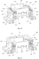
- the spring elements 118 here have essentially the same design as those in the Fig. 3 to 7 spring elements 118 shown, wherein in the Fig. 8 to 11 In the embodiment shown, however, the spring elements 118 are formed integrally with the locking element 126 assigned to them. Here, one locking element 126, together with two spring elements 118, forms a one-piece component. Here, too, the locking element 126 is arranged between two spring elements 118. The locking element 126 is connected to the fastening sections 120 of the spring elements 118, in particular to the first leg 122 of the fastening sections 120.
- the spring elements 118 are pushed with their fastening sections 120 onto the flange sections 119 of the holding frame 111, so that the spring elements 118 engage around the flange sections 119 with their fastening sections 120.
- the fastening of the locking element 126 to the holding frame 111 is effected here via the two spring elements 118 assigned to the respective locking element 126, which are fastened to a flange section 119 of the holding frame 111.
- the locking element 126 together with the two spring elements 118 connected to the locking element 126, is punched out of a sheet metal strip and bent.
- the locking element 126 has a locking tab 133, which in the inserted position, as shown in Fig. 11 shown, hooks or hooks into the recess 127 on the housing part 110.
- a tool receiving area 132 is formed on the locking tab 133, which is designed in the form of a window-like opening on the locking tab 133.
- Fig. 8 to 11 shown design The functionality when inserting the holding frame 111 into the housing part 110 is shown in Fig. 8 to 11 shown design is the same as in Fig. 3 to 7 shown design, so that particular attention should be paid to the explanations regarding the Figures 6 and 7 is referred to.
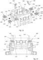
- Fig. 12 to 14 show another possible design of an assembly 100.
- the spring elements 118 are the same as those in Fig. 3 to 7 and the Fig. 8 to 11 shown spring elements 118, so that the functioning of the spring elements 118 is the same.
- the locking elements 126 shown are each formed from a displaceably mounted latching element 134 and an actuating lever 135, wherein the latching element 134 can be moved at least into an unlocked position via the actuating lever 135.
- the actuating lever 135 has a pivot axis 136, via which the actuating lever 135 is pivotally mounted on the holding frame 111.
- Two openings 137 are provided on the holding frame 111 for each actuating lever 135, in which openings the pivot axis 136 of the actuating lever 135 is rotatably mounted.
- the actuating lever 135 has a handle portion 138, via which a user can manually actuate the actuating lever 136.
- the locking element 134 of the respective locking element 126 is mounted on the holding frame 111 so as to be displaceable transversely to the insertion direction E.
- a spring element 139 in the form of a spiral spring is arranged between the actuating lever 135 and the locking element 134 of a locking element 126, which can apply a tensioning force between the actuating lever 135 and the locking element 134.
- the locking element 134 has a bent locking edge 140 with which the locking element 134 can be inserted position in the recess 127 of the housing part 110, as shown in Fig. 14 can be seen.
- the locking edge 140 is bent here at a 90° angle to the remaining area of the locking element 134.
- the spring elements 118 When inserting the holding frame 111 into the housing part 110 in the insertion direction E, the spring elements 118 first come into contact with the support sections 117 and are actuated in the same way as in the Fig. 3 to 11 shown configurations. As soon as the flange sections 119 of the holding frame 111 also rest on the support sections 117, the spring force of the spring elements 139 pushes the locking elements 134 with their locking edge 140 into the respective recess 127 on the housing part 110, where they can hook behind in order to form a fastening and thus a locking connection between the holding frame 111 and the housing part 110 in the inserted position. This locking connection can be released again by a manual pivoting movement of the actuating lever 135.
- the spring elements 118 form both an electrical contact, in particular a PE contact, between the holding frame 111 and the housing part 110 and, in the inserted position, they simultaneously exert at least a compressive force D on the locking elements 126 in order to be able to hold them securely in the respective recess 127, so that no unintentional detachment of the holding frame 111 from the housing part 110 can occur.
- the compressive force D applied by the tensioned spring elements 118 acts counter to the insertion direction E, whereby the locking elements 126 are pressed against an upper edge 143 of the respective recess 127 of the housing part 110.
- All holding frames 111 shown here have a receiving space 141 into which preferably several contact inserts can be inserted.
Landscapes
- Connector Housings Or Holding Contact Members (AREA)
- Details Of Connecting Devices For Male And Female Coupling (AREA)
Claims (15)
- Ensemble (100) formant pièce d'un connecteur enfichable, comprenant- un cadre de maintien (111) qui présente un espace de réception (141) destiné à recevoir au moins un insert de contact et qui présente au moins une partie (119) formant bride,- une partie boîtier (110) qui présente une ouverture de réception (112) dans laquelle le cadre de maintien (111) est apte à être inséré dans une direction d'insertion (E), et qui présente au moins une partie d'appui (117) formée dans l'ouverture de réception (112), et- au moins un élément de verrouillage (126), qui est agencé sur le cadre de maintien (111), l'élément de verrouillage (126) étant en prise avec la partie boîtier (110) dans une position insérée afin de verrouiller le cadre de maintien (111) sur la partie boîtier (110), caractérisé en ce que l'ensemble comprend en outre- au moins un élément à ressort (118) qui est agencé sur au moins une partie (119) formant bride et qui, pour établir un contact électrique entre le cadre de maintien (111) et la partie boîtier (110) en position insérée, repose sur au moins une partie support (117) et est mis en état de tension.
- Ensemble (100) selon la revendication 1, caractérisé en ce que l'élément à ressort (118) présente une partie d'extrémité libre (121) qui, lorsque l'élément à ressort (118) est détendu, s'étend selon un angle 10° ≤ α ≤ 40° par rapport à la partie (119) formant bride.
- Ensemble selon la revendication 1 ou la revendication 2, caractérisé en ce que l'élément à ressort (118) est plié en forme de S.
- Ensemble (100) selon l'une des revendications 1 à 3, caractérisé en ce que l'élément à ressort (118) est une pièce découpée et pliée.
- Ensemble (100) selon l'une des revendications 1 à 4, caractérisé en ce que l'élément à ressort (118) est constitué d'un matériau élastique et électriquement conducteur.
- Ensemble (100) selon l'une des revendications 1 à 5, caractérisé en ce que l'élément à ressort (118) est fixé à la partie (119) formant bride au moyen d'un assemblage par encliquetage.
- Ensemble (100) selon l'une des revendications 1 à 6, caractérisé en ce qu'au moins un évidement (127) est formé dans la partie boîtier (110), dans lequel l'élément de verrouillage (126), dans la position insérée, s'engage au moins par zones.
- Ensemble (100) selon l'une des revendications 1 à 7, caractérisé en ce que l'élément de verrouillage (126) présente une zone de réception d'outil (132) pour le transfert de l'élément de verrouillage (126) d'une position verrouillée à une position déverrouillée.
- Ensemble (100) selon l'une des revendications 1 à 8, caractérisé en ce que l'élément de verrouillage (126) est réalisé sous la forme d'un corps en fil métallique.
- Ensemble (100) selon l'une des revendications 1 à 8, caractérisé en ce que l'élément de verrouillage (126) est réalisé à partir d'une bande de tôle.
- Ensemble (100) selon l'une des revendications 1 à 7, caractérisé en ce que l'élément de verrouillage (126) est constitué par un élément à encliquetage (134) monté de manière coulissante et un levier d'actionnement (135), l'élément à encliquetage (134) étant apte à être amené dans une position verrouillée et dans une position déverrouillée au moyen du levier d'actionnement (135).
- Ensemble (100) selon l'une des revendications 1 à 11, caractérisé en ce que ledit au moins un élément de verrouillage (126) et ledit au moins un élément à ressort (118) sont formés de composants séparés les uns des autres.
- Ensemble (100) selon l'une des revendications 1 à 11, caractérisé en ce que ledit au moins un élément de verrouillage (126) et ledit au moins un élément à ressort (118) sont réalisés sous la forme d'un composant en une seule pièce.
- Pièce d'un connecteur enfichable, comprenant un ensemble (100) selon l'une des revendications 1 à 13 et comprenant au moins un insert de contact inséré dans l'espace de réception (142) du cadre de maintien (111).
- Appareil électronique, comprenant au moins un ensemble (100) réalisé selon l'une des revendications 1 à 13 et/ou comprenant au moins une pièce de connecteur enfichable selon la revendication 14.
Applications Claiming Priority (2)
| Application Number | Priority Date | Filing Date | Title |
|---|---|---|---|
| DE102020103845.3A DE102020103845A1 (de) | 2020-02-14 | 2020-02-14 | Baugruppe eines Steckverbinderteils, Steckverbinderteil und elektronisches Gerät |
| PCT/EP2021/053179 WO2021160657A1 (fr) | 2020-02-14 | 2021-02-10 | Ensemble de pièce de connecteur enfichable, pièce de connecteur enfichable et dispositif électronique |
Publications (2)
| Publication Number | Publication Date |
|---|---|
| EP4104253A1 EP4104253A1 (fr) | 2022-12-21 |
| EP4104253B1 true EP4104253B1 (fr) | 2025-04-30 |
Family
ID=74587053
Family Applications (1)
| Application Number | Title | Priority Date | Filing Date |
|---|---|---|---|
| EP21704519.4A Active EP4104253B1 (fr) | 2020-02-14 | 2021-02-10 | Ensemble de pièce de connecteur enfichable, pièce de connecteur enfichable et dispositif électronique |
Country Status (5)
| Country | Link |
|---|---|
| US (1) | US12401154B2 (fr) |
| EP (1) | EP4104253B1 (fr) |
| CN (1) | CN115104229B (fr) |
| DE (1) | DE102020103845A1 (fr) |
| WO (1) | WO2021160657A1 (fr) |
Families Citing this family (2)
| Publication number | Priority date | Publication date | Assignee | Title |
|---|---|---|---|---|
| DE102023118585A1 (de) * | 2023-07-13 | 2025-01-16 | Harting Electric Stiftung & Co. Kg | Steckverbinder mit Kontakteinsatzbefestigung |
| DE102023118586A1 (de) * | 2023-07-13 | 2025-01-16 | Harting Electric Stiftung & Co. Kg | Steckverbinder mit Kontakteinsatzbefestigung |
Family Cites Families (24)
| Publication number | Priority date | Publication date | Assignee | Title |
|---|---|---|---|---|
| US3728468A (en) * | 1972-02-16 | 1973-04-17 | C Grauer | Spring type grounding means for electrical fixtures |
| US5125854A (en) * | 1991-07-16 | 1992-06-30 | Molex Incorporated | Modular electrical connector |
| US6089882A (en) * | 1996-11-27 | 2000-07-18 | The Whitaker Corporation | Memory card connector with grounding clip |
| US6456504B1 (en) * | 2000-10-31 | 2002-09-24 | 3Com Corporation | Surface mounted grounding clip for shielded enclosures |
| US7048550B2 (en) * | 2004-06-18 | 2006-05-23 | Hon Hai Precision Ind. Co., Ltd. | Electrical adapter assembly |
| DE202005007221U1 (de) | 2005-05-06 | 2006-09-21 | Wieland Electric Gmbh | Befestigungseinsatz für einen Steckverbinder |
| DE202006016486U1 (de) * | 2006-10-24 | 2006-12-28 | Phoenix Contact Gmbh & Co. Kg | Elektronikgehäuse |
| DE102007006433A1 (de) * | 2007-02-05 | 2008-08-07 | Phoenix Contact Gmbh & Co. Kg | Anschlußbox für den elektrischen Anschluß eines Solarmoduls und Verfahren zur Montage einer Anschlußbox auf einem Solarmodul |
| CN101472378B (zh) * | 2007-12-28 | 2011-12-21 | 深圳富泰宏精密工业有限公司 | 弹片结构及应用该弹片结构的电子装置 |
| DE102008019016B4 (de) * | 2008-04-15 | 2014-12-18 | Phoenix Contact Gmbh & Co. Kg | Elektrischer Steckverbinder und Verriegelungsbügel zur Verriegelung zweier Gehäuseteile |
| US8568152B1 (en) * | 2012-04-19 | 2013-10-29 | Pass & Seymour, Inc. | Shutter assembly for electrical devices |
| DE202012010735U1 (de) * | 2012-11-12 | 2012-12-03 | Amphenol-Tuchel Electronics Gmbh | Modularer Steckverbinder |
| DE102012110907B4 (de) | 2012-11-13 | 2019-06-13 | Harting Electric Gmbh & Co. Kg | Halterahmen zur Halterung von Steckverbindermodulen |
| JP5843829B2 (ja) * | 2013-09-17 | 2016-01-13 | ヒロセ電機株式会社 | 中継電気コネクタ |
| CN203631884U (zh) * | 2013-09-17 | 2014-06-04 | 富士康(昆山)电脑接插件有限公司 | 线缆连接器组件 |
| WO2015085995A1 (fr) * | 2013-12-12 | 2015-06-18 | Harting Electric Gmbh & Co. Kg | Cadre de retenue pour un connecteur par enfichage |
| DE102014102930A1 (de) * | 2014-03-05 | 2015-09-10 | Phoenix Contact Gmbh & Co. Kg | Gehäuse für einen Steckverbinder |
| DE102015106416B3 (de) * | 2015-04-27 | 2016-06-02 | Harting Electric Gmbh & Co. Kg | Modularer Steckverbinder |
| DE102015118263A1 (de) | 2015-10-27 | 2017-04-27 | Phoenix Contact Gmbh & Co. Kg | Baugruppe eines Steckverbinderteils mit einem Halterahmen zum Aufnehmen von modularen Kontakteinsätzen |
| DE102017108433B4 (de) * | 2017-04-20 | 2021-09-30 | Harting Electric Gmbh & Co. Kg | Halterahmen für einen Steckverbinder und Verfahren zur Bestückung |
| DE102017124706A1 (de) * | 2017-10-23 | 2019-04-25 | Pilz Gmbh & Co. Kg | Tragschienengehäuse, Elektronikmodul mit einem Tragschienengehäuse und System, insbesondere Steuerungssystem, mit einer Mehrzahl von Elektronikmodulen |
| DE102017124632A1 (de) * | 2017-10-23 | 2019-04-25 | Harting Electric Gmbh & Co. Kg | Halterahmen für einen Industriesteckverbinder |
| DE102017129742A1 (de) * | 2017-12-13 | 2019-06-13 | Harting Electric Gmbh & Co. Kg | Kompaktes Anbaugehäuse |
| DE202018107326U1 (de) * | 2018-12-20 | 2019-03-27 | Phoenix Contact Gmbh & Co. Kg | Halterahmen für einen Steckverbinder |
-
2020
- 2020-02-14 DE DE102020103845.3A patent/DE102020103845A1/de active Pending
-
2021
- 2021-02-10 US US17/799,288 patent/US12401154B2/en active Active
- 2021-02-10 CN CN202180014667.5A patent/CN115104229B/zh active Active
- 2021-02-10 EP EP21704519.4A patent/EP4104253B1/fr active Active
- 2021-02-10 WO PCT/EP2021/053179 patent/WO2021160657A1/fr not_active Ceased
Also Published As
| Publication number | Publication date |
|---|---|
| CN115104229B (zh) | 2026-01-30 |
| US12401154B2 (en) | 2025-08-26 |
| CN115104229A (zh) | 2022-09-23 |
| DE102020103845A1 (de) | 2021-08-19 |
| EP4104253A1 (fr) | 2022-12-21 |
| US20240186743A1 (en) | 2024-06-06 |
| WO2021160657A1 (fr) | 2021-08-19 |
Similar Documents
| Publication | Publication Date | Title |
|---|---|---|
| DE69602306T2 (de) | Elektrischer Verbinder | |
| EP3286806A1 (fr) | Châssis de maintien permettant de maintenir des modules de connecteur à fiche | |
| EP1636880B1 (fr) | Borne de connexion ou connecteur a fiches, pour traversee de paroi, a moyens de fixation en forme de coin | |
| EP3843221B1 (fr) | Cadre de support pour un connecteur | |
| EP0735615A2 (fr) | Borne de jonction pour appareils électriques | |
| DE102022127785A1 (de) | Anschlussanordnung sowie Anschlussklemme | |
| EP4104253B1 (fr) | Ensemble de pièce de connecteur enfichable, pièce de connecteur enfichable et dispositif électronique | |
| EP3813198B1 (fr) | Dispositif de raccordement permettant de raccorder une conduite électrique | |
| EP3698439B1 (fr) | Pièce de connecteur enfichable | |
| DE102018106185B4 (de) | Kontaktelement mit einem Kontaktkörper und einem daran angeordneten Federelement | |
| EP0139980B1 (fr) | Cable clamp | |
| EP4010945B1 (fr) | Dispositif de connexion, borne de connexion et dispositif électronique | |
| EP3353860B1 (fr) | Boîtier de connexion pourvu d'un dispositif de connexion pour conducteurs | |
| EP1445840B1 (fr) | Connecteur Electrique | |
| DE102020126486A1 (de) | Halterahmen für einen Steckverbinder | |
| LU501848B1 (de) | Anschlussanordnung | |
| DE102022103633A1 (de) | Leiteranschlussklemme | |
| DE102019112612B3 (de) | Halterahmen und Steckverbinder mit einem derartigen Halterahmen | |
| EP1600332B1 (fr) | Dispositif de fixation | |
| BE1032383B1 (de) | Halterahmen für einen Steckverbinder | |
| DE102019133529B4 (de) | Kontaktierungseinrichtung zum Kontaktieren eines Schirmleiters einer elektrischen Leitung | |
| DE102019106093B4 (de) | Halterahmen sowie Steckverbinder mit einem derartigen Halterahmen | |
| DE102023132101A1 (de) | Anschlussklemme zum Anschließen einer elektrischen Leitung | |
| EP1936754A2 (fr) | Connecteur à fiches doté d'un boîtier comportant un élément d'actionnement et un moyen d'accrochage | |
| DE102024103314A1 (de) | Anschlussvorrichtung zum Anschließen eines Leiterendes |
Legal Events
| Date | Code | Title | Description |
|---|---|---|---|
| STAA | Information on the status of an ep patent application or granted ep patent |
Free format text: STATUS: UNKNOWN |
|
| STAA | Information on the status of an ep patent application or granted ep patent |
Free format text: STATUS: THE INTERNATIONAL PUBLICATION HAS BEEN MADE |
|
| PUAI | Public reference made under article 153(3) epc to a published international application that has entered the european phase |
Free format text: ORIGINAL CODE: 0009012 |
|
| STAA | Information on the status of an ep patent application or granted ep patent |
Free format text: STATUS: REQUEST FOR EXAMINATION WAS MADE |
|
| 17P | Request for examination filed |
Effective date: 20220729 |
|
| AK | Designated contracting states |
Kind code of ref document: A1 Designated state(s): AL AT BE BG CH CY CZ DE DK EE ES FI FR GB GR HR HU IE IS IT LI LT LU LV MC MK MT NL NO PL PT RO RS SE SI SK SM TR |
|
| DAV | Request for validation of the european patent (deleted) | ||
| DAX | Request for extension of the european patent (deleted) | ||
| P01 | Opt-out of the competence of the unified patent court (upc) registered |
Effective date: 20230525 |
|
| P02 | Opt-out of the competence of the unified patent court (upc) changed |
Effective date: 20230531 |
|
| GRAP | Despatch of communication of intention to grant a patent |
Free format text: ORIGINAL CODE: EPIDOSNIGR1 |
|
| STAA | Information on the status of an ep patent application or granted ep patent |
Free format text: STATUS: GRANT OF PATENT IS INTENDED |
|
| INTG | Intention to grant announced |
Effective date: 20241204 |
|
| GRAS | Grant fee paid |
Free format text: ORIGINAL CODE: EPIDOSNIGR3 |
|
| GRAA | (expected) grant |
Free format text: ORIGINAL CODE: 0009210 |
|
| STAA | Information on the status of an ep patent application or granted ep patent |
Free format text: STATUS: THE PATENT HAS BEEN GRANTED |
|
| AK | Designated contracting states |
Kind code of ref document: B1 Designated state(s): AL AT BE BG CH CY CZ DE DK EE ES FI FR GB GR HR HU IE IS IT LI LT LU LV MC MK MT NL NO PL PT RO RS SE SI SK SM TR |
|
| REG | Reference to a national code |
Ref country code: CH Ref legal event code: EP Ref country code: GB Ref legal event code: FG4D Free format text: NOT ENGLISH |
|
| REG | Reference to a national code |
Ref country code: IE Ref legal event code: FG4D Free format text: LANGUAGE OF EP DOCUMENT: GERMAN |
|
| REG | Reference to a national code |
Ref country code: DE Ref legal event code: R096 Ref document number: 502021007339 Country of ref document: DE |
|
| REG | Reference to a national code |
Ref country code: NL Ref legal event code: MP Effective date: 20250430 |
|
| PG25 | Lapsed in a contracting state [announced via postgrant information from national office to epo] |
Ref country code: PT Free format text: LAPSE BECAUSE OF FAILURE TO SUBMIT A TRANSLATION OF THE DESCRIPTION OR TO PAY THE FEE WITHIN THE PRESCRIBED TIME-LIMIT Effective date: 20250901 Ref country code: ES Free format text: LAPSE BECAUSE OF FAILURE TO SUBMIT A TRANSLATION OF THE DESCRIPTION OR TO PAY THE FEE WITHIN THE PRESCRIBED TIME-LIMIT Effective date: 20250430 Ref country code: FI Free format text: LAPSE BECAUSE OF FAILURE TO SUBMIT A TRANSLATION OF THE DESCRIPTION OR TO PAY THE FEE WITHIN THE PRESCRIBED TIME-LIMIT Effective date: 20250430 |
|
| REG | Reference to a national code |
Ref country code: LT Ref legal event code: MG9D |
|
| PG25 | Lapsed in a contracting state [announced via postgrant information from national office to epo] |
Ref country code: GR Free format text: LAPSE BECAUSE OF FAILURE TO SUBMIT A TRANSLATION OF THE DESCRIPTION OR TO PAY THE FEE WITHIN THE PRESCRIBED TIME-LIMIT Effective date: 20250731 Ref country code: NO Free format text: LAPSE BECAUSE OF FAILURE TO SUBMIT A TRANSLATION OF THE DESCRIPTION OR TO PAY THE FEE WITHIN THE PRESCRIBED TIME-LIMIT Effective date: 20250730 |
|
| PG25 | Lapsed in a contracting state [announced via postgrant information from national office to epo] |
Ref country code: NL Free format text: LAPSE BECAUSE OF FAILURE TO SUBMIT A TRANSLATION OF THE DESCRIPTION OR TO PAY THE FEE WITHIN THE PRESCRIBED TIME-LIMIT Effective date: 20250430 Ref country code: PL Free format text: LAPSE BECAUSE OF FAILURE TO SUBMIT A TRANSLATION OF THE DESCRIPTION OR TO PAY THE FEE WITHIN THE PRESCRIBED TIME-LIMIT Effective date: 20250430 |
|
| PG25 | Lapsed in a contracting state [announced via postgrant information from national office to epo] |
Ref country code: BG Free format text: LAPSE BECAUSE OF FAILURE TO SUBMIT A TRANSLATION OF THE DESCRIPTION OR TO PAY THE FEE WITHIN THE PRESCRIBED TIME-LIMIT Effective date: 20250430 |
|
| PG25 | Lapsed in a contracting state [announced via postgrant information from national office to epo] |
Ref country code: HR Free format text: LAPSE BECAUSE OF FAILURE TO SUBMIT A TRANSLATION OF THE DESCRIPTION OR TO PAY THE FEE WITHIN THE PRESCRIBED TIME-LIMIT Effective date: 20250430 |
|
| PG25 | Lapsed in a contracting state [announced via postgrant information from national office to epo] |
Ref country code: RS Free format text: LAPSE BECAUSE OF FAILURE TO SUBMIT A TRANSLATION OF THE DESCRIPTION OR TO PAY THE FEE WITHIN THE PRESCRIBED TIME-LIMIT Effective date: 20250731 |
|
| PG25 | Lapsed in a contracting state [announced via postgrant information from national office to epo] |
Ref country code: IS Free format text: LAPSE BECAUSE OF FAILURE TO SUBMIT A TRANSLATION OF THE DESCRIPTION OR TO PAY THE FEE WITHIN THE PRESCRIBED TIME-LIMIT Effective date: 20250830 |
|
| PG25 | Lapsed in a contracting state [announced via postgrant information from national office to epo] |
Ref country code: LV Free format text: LAPSE BECAUSE OF FAILURE TO SUBMIT A TRANSLATION OF THE DESCRIPTION OR TO PAY THE FEE WITHIN THE PRESCRIBED TIME-LIMIT Effective date: 20250430 |
|
| PG25 | Lapsed in a contracting state [announced via postgrant information from national office to epo] |
Ref country code: SM Free format text: LAPSE BECAUSE OF FAILURE TO SUBMIT A TRANSLATION OF THE DESCRIPTION OR TO PAY THE FEE WITHIN THE PRESCRIBED TIME-LIMIT Effective date: 20250430 Ref country code: DK Free format text: LAPSE BECAUSE OF FAILURE TO SUBMIT A TRANSLATION OF THE DESCRIPTION OR TO PAY THE FEE WITHIN THE PRESCRIBED TIME-LIMIT Effective date: 20250430 |
|
| PG25 | Lapsed in a contracting state [announced via postgrant information from national office to epo] |
Ref country code: CZ Free format text: LAPSE BECAUSE OF FAILURE TO SUBMIT A TRANSLATION OF THE DESCRIPTION OR TO PAY THE FEE WITHIN THE PRESCRIBED TIME-LIMIT Effective date: 20250430 |
|
| PG25 | Lapsed in a contracting state [announced via postgrant information from national office to epo] |
Ref country code: EE Free format text: LAPSE BECAUSE OF FAILURE TO SUBMIT A TRANSLATION OF THE DESCRIPTION OR TO PAY THE FEE WITHIN THE PRESCRIBED TIME-LIMIT Effective date: 20250430 |
|
| PG25 | Lapsed in a contracting state [announced via postgrant information from national office to epo] |
Ref country code: SK Free format text: LAPSE BECAUSE OF FAILURE TO SUBMIT A TRANSLATION OF THE DESCRIPTION OR TO PAY THE FEE WITHIN THE PRESCRIBED TIME-LIMIT Effective date: 20250430 |
|
| REG | Reference to a national code |
Ref country code: DE Ref legal event code: R097 Ref document number: 502021007339 Country of ref document: DE |
|
| PLBE | No opposition filed within time limit |
Free format text: ORIGINAL CODE: 0009261 |
|
| STAA | Information on the status of an ep patent application or granted ep patent |
Free format text: STATUS: NO OPPOSITION FILED WITHIN TIME LIMIT |
|
| REG | Reference to a national code |
Ref country code: CH Ref legal event code: L10 Free format text: ST27 STATUS EVENT CODE: U-0-0-L10-L00 (AS PROVIDED BY THE NATIONAL OFFICE) Effective date: 20260311 |
|
| 26N | No opposition filed |
Effective date: 20260202 |
|
| PGFP | Annual fee paid to national office [announced via postgrant information from national office to epo] |
Ref country code: IT Payment date: 20260220 Year of fee payment: 6 |