EP1445877A2 - Kommunikation zwischen elektromagnetischen Transpondern - Google Patents
Kommunikation zwischen elektromagnetischen Transpondern Download PDFInfo
- Publication number
- EP1445877A2 EP1445877A2 EP03300208A EP03300208A EP1445877A2 EP 1445877 A2 EP1445877 A2 EP 1445877A2 EP 03300208 A EP03300208 A EP 03300208A EP 03300208 A EP03300208 A EP 03300208A EP 1445877 A2 EP1445877 A2 EP 1445877A2
- Authority
- EP
- European Patent Office
- Prior art keywords
- transponder
- frequency
- terminal
- decoder
- subcarrier
- Prior art date
- Legal status (The legal status is an assumption and is not a legal conclusion. Google has not performed a legal analysis and makes no representation as to the accuracy of the status listed.)
- Granted
Links
Images
Classifications
-
- G—PHYSICS
- G06—COMPUTING OR CALCULATING; COUNTING
- G06K—GRAPHICAL DATA READING; PRESENTATION OF DATA; RECORD CARRIERS; HANDLING RECORD CARRIERS
- G06K19/00—Record carriers for use with machines and with at least a part designed to carry digital markings
- G06K19/06—Record carriers for use with machines and with at least a part designed to carry digital markings characterised by the kind of the digital marking, e.g. shape, nature, code
- G06K19/067—Record carriers with conductive marks, printed circuits or semiconductor circuit elements, e.g. credit or identity cards also with resonating or responding marks without active components
- G06K19/07—Record carriers with conductive marks, printed circuits or semiconductor circuit elements, e.g. credit or identity cards also with resonating or responding marks without active components with integrated circuit chips
- G06K19/0723—Record carriers with conductive marks, printed circuits or semiconductor circuit elements, e.g. credit or identity cards also with resonating or responding marks without active components with integrated circuit chips the record carrier comprising an arrangement for non-contact communication, e.g. wireless communication circuits on transponder cards, non-contact smart cards or RFIDs
Definitions
- the present invention relates to systems using electromagnetic transponders, i.e. transmitters generally mobile receivers capable of being interrogated, contactless and wireless, by a generally fixed unit, called reading and / or writing terminal.
- the invention relates, more in particular, transponders without autonomous power supply, for example of the contactless card or electronic label type. These transponders extract the necessary power to electronic circuits that they contain high frequency field radiated by an antenna of the reading terminal and writing.
- the invention applies to such transponders, that it are read-only transponders, i.e. clean to operate with a terminal simply reading the data transponder, or read-write transponders which contain data which can be modified by the terminal.
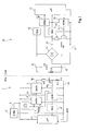
- FIG 1 shows, very schematically and functional, a classic example of data exchange between a read-write terminal 1 (STA) and a transponder 10 (BECAUSE).
- STA read-write terminal 1
- BECAUSE transponder 10
- Terminal 1 essentially consists of a circuit oscillating formed by an inductor L1, in series with a capacitor C1 and a resistor R1, between a 2p output terminal an antenna amplifier or coupler 3 and a 2m terminal at a reference potential (usually mass).
- the amplifier 3 receives a high frequency transmission signal Tx, coming from a modulator 4 (MOD).
- the modulator receives a frequency of reference, for example of a quartz oscillator 5 and, if need, a DATA signal of data to be transmitted.
- the Tx signal serves only as an energy source to activate the transponder 10 if it goes into the field.
- the data to transmit generally come from a digital system, by example, a microprocessor 6 ( ⁇ P).
- the connection point of capacitor C1 and inductance L1 constitutes, in the example represented in figure 1, a terminal for sampling an Rx signal of received data a transponder 10 to a demodulator (DEM).
- a output of the demodulator communicates (if necessary via a decoder 8 (DEC)) the data received from the transponder 10 to the microprocessor 6 of terminal 1.
- the demodulator 7 receives, generally from oscillator 5, a clock signal or standard for phase demodulation. If applicable, the demodulation is carried out from a signal taken between the capacitor C1 and resistor R1, not across inductance L1.
- Microprocessor 6 communicates (BUS) with different input / output circuits (keyboard, screen, means of transmission to a server, etc.) and / or processing.
- the read / write terminal circuits draw the necessary energy to their operation of a supply circuit 9 (ALIM) connected, for example, to the electrical distribution network.
- ALEM supply circuit 9
- Transponder side 10 an inductor L2, in parallel with a capacitor C2, forms a parallel oscillating circuit (called resonant circuit in reception), intended to receive the magnetic field generated by the L1, C1 series oscillating circuit of terminal 1.
- the resonant circuit (L2, C2) of the transponder 10 is tuned to the resonant frequency of the oscillating circuit from terminal 1.
- Terminals 11 and 12 of the resonant circuit L2, C2 which correspond to the terminals of the capacitor C2 are connected to two alternative input terminals of a rectifier bridge 13 whose rectified output terminals 14 and 15 are connected to the terminals of a capacitor Ca for energy storage and smoothing of the rectified voltage supplied by bridge 13.
- Bridge 13 is mono or double alternation.
- a high frequency voltage is generated across the resonant circuit L2, C2.
- This voltage rectified by bridge 13 is smoothed by the capacitor Ca which provides a voltage supply to electronic circuits of the transponder by via a voltage regulator 16 (REG).
- These circuits generally include, essentially a microprocessor 17 ( ⁇ P) associated with a memory not shown, a demodulator 18 (DEM) of the signals possibly received from the terminal 1, and a modulator 19 (MOD) for transmitting information at terminal 1.
- the transponder is generally synchronized by means of a clock (CLK) extracted by a block 20 of the high frequency signal recovered across capacitor C2 before recovery. Most often, all electronic circuits of the transponder 10 are integrated into the same chip.
- CLK clock
- modulator 19 controls a modulation stage (retromodulation) of the resonant circuit L2, C2.
- This floor of modulation usually consists of an electronic switch (for example, a transistor T) and a resistor R, in series between terminals 14 and 15.
- the transistor T is controlled at a frequency (by example, 847.5 kHz) called subcarrier, significantly lower (generally, with a ratio of at least 10) to the frequency of terminal 1 oscillating circuit excitation signal (by example 13.56 MHz).
- a frequency by example, 847.5 kHz
- subcarrier significantly lower (generally, with a ratio of at least 10) to the frequency of terminal 1 oscillating circuit excitation signal (by example 13.56 MHz).
- switch T When switch T is closed, the oscillating circuit of the transponder is subject to damping additional to the load created by the circuits 16 to 20, so that the transponder takes a higher amount of energy from the high magnetic field frequency.
- amplifier 3 keeps constant the amplitude of the high frequency excitation signal. Through therefore, the energy variation of the transponder is reflected by a variation in amplitude and phase of the current in the L1 antenna. This variation is detected by the demodulator 7 of the terminal which is either a phase demodulator or a amplitude demodul
- the retromodulation stage (transistor T, resistance R) is located upstream of the bridge 13, i.e. side of its alternative inputs.
- the terminal generally does not transmit data during that it receives from the transponder, the transmission taking place alternately in one direction then in the other.
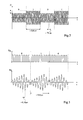
- Figure 2 illustrates a classic example of transmission data from terminal 1 to a transponder 10.
- This figure shows an example of the shape of the excitation signal of antenna L1 for transmission of a code 0101.
- Modulation commonly used is amplitude modulation with flow 106 kilobits per second (1 bit is transmitted in approximately 9.5 significantly lower than the frequency (for example, 13.56 MHz) from the carrier from oscillator 5 (period about 74 nanoseconds).
- Amplitude modulation takes place, either all or nothing, or with a modulation rate (defined as the difference of the peak amplitudes (a, b) between the two states (0 and 1) divided by the sum of these amplitudes) less than unity due to the transponder's power requirement 10.
- the carrier at 13.56 MHz is modulated, with a throughput of 106 kilobits per second, in amplitude with a modulation rate tm of, for example, 10%.
- FIG. 3 illustrates a classic example of data transmission from the transponder 10 to terminal 1.
- This figure illustrates an example of the shape of the signal V T for controlling the transistor T, supplied by the modulator 19, and the corresponding signal Rx received by terminal 1.
- the back modulation is generally of the resistive type with a carrier known as a subcarrier of, for example, 847.5 kHz (period of approximately 1.18 ms).
- the back modulation is, for example, based on a BPSK type coding (binary coding by phase jump) with a bit rate of the order of 106 kilobits per second much lower than the frequency of the subcarrier.
- modulation e.g. amplitude, phase, frequency
- NRZ NRZI, Manchester, ASK, BPSK, etc.
- the modulation is carried out numerically, by jumping between two binary levels.
- the signal V T consists of a train of pulses at the frequency of the subcarrier, a phase jump occurring at each change of state from one bit to the next bit.
- transponders If several transponders are located in the field from the same terminal, different communications can be initiated between each transponder and the read-write terminal. Most often, transponders transmit identifiers that allow the terminal to individualize messages to their respective destinations.
- the transponders determine whether messages are theirs respectively intended from their identifier contained in the message, that they detect after demodulation.
- the terminal serves as an intermediary for this communication receiving information from a transponder to retransmit them to another having previously demodulated and then remodulated.
- the present invention aims to propose a new information exchange solution between two transponders in the field of a read-write terminal.
- the invention also aims to propose a solution which does not require any modification of the read-write terminals existing.
- the invention also aims to propose a solution which resolves conflict issues when two transponders are present in the field of a terminal read-write with which they communicate.
- this invention provides an electromagnetic transponder for take the energy necessary for its operation from a field radiated by a transmission terminal from a carrier to a first remote power frequency and back-modulating the received signal at the rate of a subcarrier at a second lower frequency to the first, and comprising means suitable for demodulating and decoding signals modulated by said subcarrier.
- the transponder comprises an oscillating circuit upstream of a rectifying means capable of supplying a DC voltage supply of an electronic circuit, the electronic circuit comprising means for transmitting coded information digitally, and the transponder comprising a demodulator able to differentiate information received at the rate of retromodulation subcarrier of another transponder by report received, at the rate of a third even lower frequency, from the read-write terminal.
- said demodulator comprises two parallel branches having each a filter centered respectively on the second and third frequencies, each filter being associated with a decoder digital.
- a first decoder associated with the filter centered on the frequency of retromodulation is a phase jump type decoder, a second decoder associated with the third frequency being a amplitude jump type decoder.
- the invention also provides a communication system contactless and wireless between at least two transponders electromagnetic without autonomous power, each transponder comprising means suitable for taking energy necessary to power its circuits, an electronic field at a first remote power frequency radiated by at least one read-write terminal, and means for demodulate and decode signals from another transponder in modulation of a subcarrier at a second frequency.
- each transponder has demodulators and decoders separate dedicated respectively to the reception of transmitted signals by another transponder and upon reception of signals transmitted by the read-write terminal.
- the first frequency is 13.56 MHz
- the second frequency being at 847.5 kHz
- the third frequency being at 106.5 kHz.
- a feature of the present invention is provide direct communication between two transponders electromagnetic present in the field of a terminal read-write where they get their power from.
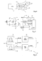
- Figure 4 illustrates very schematically and in the form of blocks, an embodiment of a system of communication according to the present invention.
- a reader 1 generates by through an inductance antenna L1 an electromagnetic field at a frequency corresponding to a carrier of remote supply of transponders 10 (T1, T2).
- Each transponder itself includes an antenna (inductors L21, L22) used to capture the electromagnetic radiation from the terminal to draw power from its internal circuits.
- the transponders 10 are, according to the invention, capable not only to communicate with terminal 1 but also directly between them as illustrated by the two-way arrows in Figure 4.
- a first embodiment of the invention we use the same receiver to receive the information coming from the terminal (for example, at a frequency of 106 kHz) and information from another transponder in back modulation (for example, at a frequency of 847.5 kHz).
- the transponder demodulator downstream of the transponder demodulator, several decoders according to the type of information to be detected. This are then these decoders which differentiate the transmissions to 106 kilobits of transmissions at the frequency of 847.5 kHz.
- FIG. 5 represents, in the form of blocks and very schematically, a transponder according to the first mode of realization of the invention.
- FIG. 5 illustrates a variant of the retromodulation circuit in which the retromodulation transistor T is alone placed in parallel on the capacitor Ca, its series resistance in the state passing constituting the retromodulation resistance.
- the output of the demodulator 28 is sent on two decoders 25 and 26 (DEC1 and DEC2) intended for each decode one of the types of signals likely to be received, i.e. those received at the rate of 106 kilobits per second from terminal 1 and those received at the rate of 847.5 kHz from another transponder.
- the demodulator 28 specific to the invention comprises a analog head 29 (ADH) providing the envelope of the received signal and carried by the frequency of 13.56 MHz.
- ADH analog head 29
- This envelope is, either modulated to the rate of the back-modulation carrier 847.5 kilohertz, or at the terminal transmission rate (106 kHz).
- each DEC1 or DEC2 decoder is capable of detecting level variations depending on whether they are at the rhythm of 106 kHz or at the rate of 847.5 kHz.
- the respective decoder outputs provide the demodulated signals respectively from the terminal or other transponder in the field and in coupling close with the transponder concerned.
- FIG. 6 represents a second embodiment a decoder 30 according to the invention.
- the exit 14 of the bridge rectifier is connected to the respective inputs of two filters 31 and 32 respectively centered on the frequencies of 847.5 kHz and 106 kHz, for example, corresponding to the back modulation frequencies and terminal modulation.
- the respective outings filters 31 and 32 therefore reproduce digital signals demodulated only if the received signal contains information at the corresponding frequency.
- the filter 31 is followed by a BPSK type 33 decoder whose output provides a bit stream to circuit 17.
- Filter 32 is associated with a ASK decoder 34 whose output provides a bit stream decoded on circuit 17.
- FIG. 6 takes advantage of the fact that in transponder transmission systems electromagnetic, transmission from the reader to a transponder is generally done by an ASK modulation (jump amplitude) at a frequency of 106 kHz while the transmission from a transponder to a reader (or for the invention to another transponder) is effected by modulation by phase jump (BPSK) with a modulation frequency of 847 kHz.
- ASK modulation jump amplitude
- BPSK phase jump
- An advantage of the present invention is that it does not requires no modification of the transponders which concerns the modulation part.
- the invention requires only modification of the demodulation part of the transponders for be able to interpret information from a other transponder within the range of a terminal, sufficient close for mutual coupling between two transponders.
- Another advantage of the present invention is that allowing direct communication between two transponders, potential conflict issues can be resolved when multiple transponders are present in the field of the same thick headed. Indeed, from the moment a transponder picks up information directly from another transponder thanks to the invention, one can provide for it a ban on broadcasting at the same time so management time of transponder communications to the same terminal is managed directly by transponders.
- the present invention may allow, for example, recharging a transport card from a wallet card electronics by coupling the latter two in the same field (the reader then only being used to generate a field magnetic feed of these cards). The devices corresponding security can then remain in the cards, this which improves the reliability of systems against hacking.
- the direct communication between two cards can also allow communication priority detection when these are in the field of the same terminal.
Landscapes
- Engineering & Computer Science (AREA)
- Computer Networks & Wireless Communication (AREA)
- Computer Hardware Design (AREA)
- Microelectronics & Electronic Packaging (AREA)
- Physics & Mathematics (AREA)
- General Physics & Mathematics (AREA)
- Theoretical Computer Science (AREA)
- Near-Field Transmission Systems (AREA)
- Radar Systems Or Details Thereof (AREA)
Applications Claiming Priority (2)
| Application Number | Priority Date | Filing Date | Title |
|---|---|---|---|
| FR0214201 | 2002-11-13 | ||
| FR0214201 | 2002-11-13 |
Publications (3)
| Publication Number | Publication Date |
|---|---|
| EP1445877A2 true EP1445877A2 (de) | 2004-08-11 |
| EP1445877A3 EP1445877A3 (de) | 2004-08-25 |
| EP1445877B1 EP1445877B1 (de) | 2006-05-24 |
Family
ID=32338649
Family Applications (1)
| Application Number | Title | Priority Date | Filing Date |
|---|---|---|---|
| EP03300208A Expired - Lifetime EP1445877B1 (de) | 2002-11-13 | 2003-11-12 | Kommunikation zwischen elektromagnetischen Transpondern |
Country Status (3)
| Country | Link |
|---|---|
| US (1) | US7308249B2 (de) |
| EP (1) | EP1445877B1 (de) |
| DE (1) | DE60305433T2 (de) |
Families Citing this family (18)
| Publication number | Priority date | Publication date | Assignee | Title |
|---|---|---|---|---|
| EP1721406A1 (de) * | 2004-02-27 | 2006-11-15 | Koninklijke Philips Electronics N.V. | Rücksetzschaltung, datenträger und kommunikationseinrichtung |
| FR2873243A1 (fr) | 2004-07-13 | 2006-01-20 | St Microelectronics Sa | Circuit d'alimentation adaptable |
| JP2006042214A (ja) * | 2004-07-29 | 2006-02-09 | Nec Electronics Corp | 半導体装置およびicタグ |
| GB0425423D0 (en) * | 2004-11-18 | 2004-12-22 | Innovision Res & Tech Plc | Rfid system |
| FR2879754A1 (fr) * | 2004-12-20 | 2006-06-23 | St Microelectronics Sa | Transpondeur electromagnetique depourvu d'alimentation autonome |
| EP1691481B1 (de) * | 2005-02-12 | 2014-04-02 | TRUMPF Hüttinger GmbH + Co. KG | Amplitudenmodulator |
| US7843345B2 (en) * | 2007-03-05 | 2010-11-30 | Texas Instruments Incorporated | Dual frequency RFID circuit |
| JP5155642B2 (ja) * | 2007-11-28 | 2013-03-06 | ルネサスエレクトロニクス株式会社 | Idタグ |
| FR2947075A1 (fr) * | 2009-06-19 | 2010-12-24 | St Microelectronics Rousset | Evaluation resistive du facteur de couplage d'un transpondeur electromagnetique |
| TW201112126A (en) * | 2009-09-18 | 2011-04-01 | Univ Nat Taiwan Science Tech | Radio frequency identification tag |
| DE102009029646B4 (de) * | 2009-09-21 | 2014-05-22 | Niki Efstathiou | Plakettenidentifizierung |
| FR2960993A1 (fr) | 2010-06-03 | 2011-12-09 | St Microelectronics Rousset | Evaluation du facteur de couplage d'un transpondeur electromagnetique par desaccord capacitif |
| FR2976105B1 (fr) | 2011-06-03 | 2013-05-17 | St Microelectronics Rousset | Securisation d'une communication par un transpondeur electromagnetique |
| FR2976102B1 (fr) | 2011-06-03 | 2013-05-17 | St Microelectronics Rousset | Assistance au positionnement d'un transpondeur |
| FR2976104B1 (fr) | 2011-06-03 | 2013-11-15 | St Microelectronics Rousset | Securisation d'une communication entre un transpondeur electromagnetique et un terminal |
| FR2976103B1 (fr) | 2011-06-03 | 2013-05-17 | St Microelectronics Rousset | Aide au positionnement d'un transpondeur |
| US10129889B1 (en) * | 2015-09-01 | 2018-11-13 | Sprint Spectrum L.P. | Selecting primary and secondary component carriers for carrier aggregation based on carrier receive power at a UE, transmit power, frequency, and other carrier attributes |
| CN113960952B (zh) * | 2021-12-22 | 2022-04-15 | 四川承天翼航空科技有限公司 | 无接触电磁控制和执行系统 |
Family Cites Families (16)
| Publication number | Priority date | Publication date | Assignee | Title |
|---|---|---|---|---|
| US5347280A (en) | 1993-07-02 | 1994-09-13 | Texas Instruments Deutschland Gmbh | Frequency diversity transponder arrangement |
| US5541604A (en) * | 1993-09-03 | 1996-07-30 | Texas Instruments Deutschland Gmbh | Transponders, Interrogators, systems and methods for elimination of interrogator synchronization requirement |
| US5517194A (en) * | 1994-02-10 | 1996-05-14 | Racom Systems, Inc. | Passive RF transponder and method |
| US5434572A (en) * | 1994-06-07 | 1995-07-18 | Ramtron International Corporation | System and method for initiating communications between a controller and a selected subset of multiple transponders in a common RF field |
| US5550536A (en) * | 1994-08-17 | 1996-08-27 | Texas Instruments Deutschland Gmbh | Circuit frequency following technique transponder resonant |
| JPH08191259A (ja) * | 1995-01-11 | 1996-07-23 | Sony Chem Corp | 非接触式icカードシステム用送受信装置 |
| US6107910A (en) | 1996-11-29 | 2000-08-22 | X-Cyte, Inc. | Dual mode transmitter/receiver and decoder for RF transponder tags |
| US6456668B1 (en) * | 1996-12-31 | 2002-09-24 | Lucent Technologies Inc. | QPSK modulated backscatter system |
| EP0953181B8 (de) * | 1997-01-17 | 2005-10-05 | Tagsys SA | Multiples etikettenlesesystem |
| FR2792134B1 (fr) * | 1999-04-07 | 2001-06-22 | St Microelectronics Sa | Detection de distance entre un transpondeur electromagnetique et une borne |
| US6307468B1 (en) * | 1999-07-20 | 2001-10-23 | Avid Identification Systems, Inc. | Impedance matching network and multidimensional electromagnetic field coil for a transponder interrogator |
| ATE396458T1 (de) * | 2000-03-22 | 2008-06-15 | Infineon Technologies Ag | Chipkarte |
| FR2808634A1 (fr) * | 2000-05-05 | 2001-11-09 | St Microelectronics Sa | Amelioration de la capacite de demodulation d'un transpondeur electromagnetique |
| US6868073B1 (en) | 2000-06-06 | 2005-03-15 | Battelle Memorial Institute K1-53 | Distance/ranging by determination of RF phase delta |
| EP1758046A1 (de) | 2000-06-12 | 2007-02-28 | BTG International Limited | Seitenbanddiversitätsleser für elektronische Identifikationssysteme |
| US6920330B2 (en) * | 2002-03-26 | 2005-07-19 | Sun Microsystems, Inc. | Apparatus and method for the use of position information in wireless applications |
-
2003
- 2003-11-12 EP EP03300208A patent/EP1445877B1/de not_active Expired - Lifetime
- 2003-11-12 US US10/712,325 patent/US7308249B2/en not_active Expired - Lifetime
- 2003-11-12 DE DE60305433T patent/DE60305433T2/de not_active Expired - Lifetime
Also Published As
| Publication number | Publication date |
|---|---|
| DE60305433T2 (de) | 2006-12-28 |
| DE60305433D1 (de) | 2006-06-29 |
| EP1445877A3 (de) | 2004-08-25 |
| EP1445877B1 (de) | 2006-05-24 |
| US20040104809A1 (en) | 2004-06-03 |
| US7308249B2 (en) | 2007-12-11 |
Similar Documents
| Publication | Publication Date | Title |
|---|---|---|
| EP1445877B1 (de) | Kommunikation zwischen elektromagnetischen Transpondern | |
| EP1043680B1 (de) | Enggekoppelter elektromagnetischer Transponder | |
| EP1045325B1 (de) | Entfernungsbestimmung zwischen einem elektromagnetischen Transponder und einem Terminal | |
| EP1045336B1 (de) | Enggekoppeltes Betriebsverfahren eines elektromagnetischen Transpondersystem | |
| EP1043677B1 (de) | Ein mit sehr naher Koppelung arbeitendes Lesegerät für elektromagnetische Transponder | |
| EP1327222B1 (de) | Kontaktloses lesegerät für integrierte schaltung | |
| CA2245905A1 (fr) | Systeme d'echange de donnees a communication par contacts ou sans contact entre une borne et des objets portatifs | |
| EP1774458B1 (de) | Ladungsmodulation bei einem elektromagnetischen Transponder | |
| EP1312032A1 (de) | Hochempfindlicher leser für passive transponder | |
| EP1043678B1 (de) | Duplexübertragung in einem elektromagnetischen Transponder-System | |
| EP1014300A1 (de) | Kapazitive Modulation in einem elektomagnetischen Transponder | |
| EP1043679B1 (de) | Leser mit Einrichtung zur Bestimmung des Abstandes zwischen dem Leser und einem Transponder | |
| EP1163734B1 (de) | Schaltungsanordnung zum empfangen und senden von daten mit induktiver kopplung | |
| EP1062621B1 (de) | Verfahren, system und vorrichtung zur informationsübertragung durch elektromagnetische verbindung zwischen lesegeräten und nomadischen objekten | |
| FR2791489A1 (fr) | Procede de modulation de l'amplitude d'un signal d'antenne | |
| CA2297797A1 (fr) | Objet portatif a communication sans contact suivant deux voies de communication, inductive et hertzienne | |
| EP1039408A1 (de) | Fernspeisung für einen elektromagnetischen Transponder | |
| FR2763445A1 (fr) | Borne de communication sans contact, au moyen d'un procede a induction, avec des objets portatifs de types differents | |
| FR2792133A1 (fr) | Regulation de phase d'un lecteur de transpondeurs electromagnetiques | |
| FR2790155A1 (fr) | Borne de communication sans contact par induction avec des objets portatifs, comportant un demodulateur bpsk |
Legal Events
| Date | Code | Title | Description |
|---|---|---|---|
| PUAI | Public reference made under article 153(3) epc to a published international application that has entered the european phase |
Free format text: ORIGINAL CODE: 0009012 |
|
| PUAL | Search report despatched |
Free format text: ORIGINAL CODE: 0009013 |
|
| AK | Designated contracting states |
Kind code of ref document: A2 Designated state(s): AT BE BG CH CY CZ DE DK EE ES FI FR GB GR HU IE IT LI LU MC NL PT RO SE SI SK TR |
|
| AX | Request for extension of the european patent |
Extension state: AL LT LV MK |
|
| AK | Designated contracting states |
Kind code of ref document: A3 Designated state(s): AT BE BG CH CY CZ DE DK EE ES FI FR GB GR HU IE IT LI LU MC NL PT RO SE SI SK TR |
|
| AX | Request for extension of the european patent |
Extension state: AL LT LV MK |
|
| RIC1 | Information provided on ipc code assigned before grant |
Ipc: 7H 04B 5/02 A Ipc: 7G 01S 13/02 B Ipc: 7G 06K 19/07 B |
|
| 17P | Request for examination filed |
Effective date: 20050223 |
|
| 17Q | First examination report despatched |
Effective date: 20050324 |
|
| AKX | Designation fees paid |
Designated state(s): DE FR GB IT |
|
| RBV | Designated contracting states (corrected) |
Designated state(s): DE FR GB IT |
|
| GRAP | Despatch of communication of intention to grant a patent |
Free format text: ORIGINAL CODE: EPIDOSNIGR1 |
|
| GRAS | Grant fee paid |
Free format text: ORIGINAL CODE: EPIDOSNIGR3 |
|
| GRAA | (expected) grant |
Free format text: ORIGINAL CODE: 0009210 |
|
| AK | Designated contracting states |
Kind code of ref document: B1 Designated state(s): DE FR GB IT |
|
| PG25 | Lapsed in a contracting state [announced via postgrant information from national office to epo] |
Ref country code: IT Free format text: LAPSE BECAUSE OF FAILURE TO SUBMIT A TRANSLATION OF THE DESCRIPTION OR TO PAY THE FEE WITHIN THE PRESCRIBED TIME-LIMIT;WARNING: LAPSES OF ITALIAN PATENTS WITH EFFECTIVE DATE BEFORE 2007 MAY HAVE OCCURRED AT ANY TIME BEFORE 2007. THE CORRECT EFFECTIVE DATE MAY BE DIFFERENT FROM THE ONE RECORDED. Effective date: 20060524 |
|
| REG | Reference to a national code |
Ref country code: GB Ref legal event code: FG4D Free format text: NOT ENGLISH |
|
| REF | Corresponds to: |
Ref document number: 60305433 Country of ref document: DE Date of ref document: 20060629 Kind code of ref document: P |
|
| GBT | Gb: translation of ep patent filed (gb section 77(6)(a)/1977) |
Effective date: 20060906 |
|
| PLBE | No opposition filed within time limit |
Free format text: ORIGINAL CODE: 0009261 |
|
| STAA | Information on the status of an ep patent application or granted ep patent |
Free format text: STATUS: NO OPPOSITION FILED WITHIN TIME LIMIT |
|
| 26N | No opposition filed |
Effective date: 20070227 |
|
| PGFP | Annual fee paid to national office [announced via postgrant information from national office to epo] |
Ref country code: DE Payment date: 20101025 Year of fee payment: 8 |
|
| PGFP | Annual fee paid to national office [announced via postgrant information from national office to epo] |
Ref country code: GB Payment date: 20101026 Year of fee payment: 8 Ref country code: IT Payment date: 20101104 Year of fee payment: 8 |
|
| PGFP | Annual fee paid to national office [announced via postgrant information from national office to epo] |
Ref country code: FR Payment date: 20111205 Year of fee payment: 9 |
|
| GBPC | Gb: european patent ceased through non-payment of renewal fee |
Effective date: 20121112 |
|
| REG | Reference to a national code |
Ref country code: FR Ref legal event code: ST Effective date: 20130731 |
|
| PG25 | Lapsed in a contracting state [announced via postgrant information from national office to epo] |
Ref country code: IT Free format text: LAPSE BECAUSE OF NON-PAYMENT OF DUE FEES Effective date: 20121112 |
|
| REG | Reference to a national code |
Ref country code: DE Ref legal event code: R119 Ref document number: 60305433 Country of ref document: DE Effective date: 20130601 |
|
| PG25 | Lapsed in a contracting state [announced via postgrant information from national office to epo] |
Ref country code: DE Free format text: LAPSE BECAUSE OF NON-PAYMENT OF DUE FEES Effective date: 20130601 |
|
| PG25 | Lapsed in a contracting state [announced via postgrant information from national office to epo] |
Ref country code: GB Free format text: LAPSE BECAUSE OF NON-PAYMENT OF DUE FEES Effective date: 20121112 Ref country code: FR Free format text: LAPSE BECAUSE OF NON-PAYMENT OF DUE FEES Effective date: 20121130 |