EP1446242B1 - Verfahren und vorrichtung zur kontinuierlichen herstellung eines gewalzten metallbandes aus einer metallschmelze - Google Patents
Verfahren und vorrichtung zur kontinuierlichen herstellung eines gewalzten metallbandes aus einer metallschmelze Download PDFInfo
- Publication number
- EP1446242B1 EP1446242B1 EP02781241A EP02781241A EP1446242B1 EP 1446242 B1 EP1446242 B1 EP 1446242B1 EP 02781241 A EP02781241 A EP 02781241A EP 02781241 A EP02781241 A EP 02781241A EP 1446242 B1 EP1446242 B1 EP 1446242B1
- Authority
- EP
- European Patent Office
- Prior art keywords
- strip
- metal
- rolling stand
- diverting device
- roll
- Prior art date
- Legal status (The legal status is an assumption and is not a legal conclusion. Google has not performed a legal analysis and makes no representation as to the accuracy of the status listed.)
- Expired - Lifetime
Links
- 239000002184 metal Substances 0.000 title claims abstract description 81
- 238000000034 method Methods 0.000 title claims abstract description 20
- 238000010924 continuous production Methods 0.000 title claims description 4
- 238000005096 rolling process Methods 0.000 claims abstract description 51
- 238000005266 casting Methods 0.000 claims abstract description 24
- 238000011144 upstream manufacturing Methods 0.000 claims abstract description 18
- 238000009434 installation Methods 0.000 claims description 13
- 238000004519 manufacturing process Methods 0.000 claims description 12
- 230000008569 process Effects 0.000 claims description 12
- 229910000831 Steel Inorganic materials 0.000 claims description 6
- 239000010959 steel Substances 0.000 claims description 6
- 238000006073 displacement reaction Methods 0.000 claims description 4
- 230000000694 effects Effects 0.000 claims description 4
- 230000009471 action Effects 0.000 claims description 3
- 230000008878 coupling Effects 0.000 claims description 3
- 238000010168 coupling process Methods 0.000 claims description 3
- 238000005859 coupling reaction Methods 0.000 claims description 3
- 230000007246 mechanism Effects 0.000 claims description 2
- 238000003780 insertion Methods 0.000 abstract 1
- 230000037431 insertion Effects 0.000 abstract 1
- 238000007665 sagging Methods 0.000 description 5
- 208000027418 Wounds and injury Diseases 0.000 description 3
- 230000008901 benefit Effects 0.000 description 3
- 238000010276 construction Methods 0.000 description 2
- 238000001816 cooling Methods 0.000 description 2
- 230000009467 reduction Effects 0.000 description 2
- 230000001105 regulatory effect Effects 0.000 description 2
- 230000006641 stabilisation Effects 0.000 description 2
- 238000011105 stabilization Methods 0.000 description 2
- 238000009966 trimming Methods 0.000 description 2
- 238000004804 winding Methods 0.000 description 2
- 206010065433 Ligament rupture Diseases 0.000 description 1
- 239000011324 bead Substances 0.000 description 1
- 238000005520 cutting process Methods 0.000 description 1
- 230000001419 dependent effect Effects 0.000 description 1
- 238000011161 development Methods 0.000 description 1
- 230000001939 inductive effect Effects 0.000 description 1
- 238000005259 measurement Methods 0.000 description 1
- 238000013508 migration Methods 0.000 description 1
- 230000003287 optical effect Effects 0.000 description 1
- 238000012545 processing Methods 0.000 description 1
- 238000007712 rapid solidification Methods 0.000 description 1
- 230000000087 stabilizing effect Effects 0.000 description 1
- 239000007858 starting material Substances 0.000 description 1
Images


Classifications
-
- B—PERFORMING OPERATIONS; TRANSPORTING
- B21—MECHANICAL METAL-WORKING WITHOUT ESSENTIALLY REMOVING MATERIAL; PUNCHING METAL
- B21B—ROLLING OF METAL
- B21B1/00—Metal-rolling methods or mills for making semi-finished products of solid or profiled cross-section; Sequence of operations in milling trains; Layout of rolling-mill plant, e.g. grouping of stands; Succession of passes or of sectional pass alternations
- B21B1/46—Metal-rolling methods or mills for making semi-finished products of solid or profiled cross-section; Sequence of operations in milling trains; Layout of rolling-mill plant, e.g. grouping of stands; Succession of passes or of sectional pass alternations for rolling metal immediately subsequent to continuous casting
-
- B—PERFORMING OPERATIONS; TRANSPORTING
- B21—MECHANICAL METAL-WORKING WITHOUT ESSENTIALLY REMOVING MATERIAL; PUNCHING METAL
- B21B—ROLLING OF METAL
- B21B1/00—Metal-rolling methods or mills for making semi-finished products of solid or profiled cross-section; Sequence of operations in milling trains; Layout of rolling-mill plant, e.g. grouping of stands; Succession of passes or of sectional pass alternations
- B21B1/46—Metal-rolling methods or mills for making semi-finished products of solid or profiled cross-section; Sequence of operations in milling trains; Layout of rolling-mill plant, e.g. grouping of stands; Succession of passes or of sectional pass alternations for rolling metal immediately subsequent to continuous casting
- B21B1/463—Metal-rolling methods or mills for making semi-finished products of solid or profiled cross-section; Sequence of operations in milling trains; Layout of rolling-mill plant, e.g. grouping of stands; Succession of passes or of sectional pass alternations for rolling metal immediately subsequent to continuous casting in a continuous process, i.e. the cast not being cut before rolling
-
- B—PERFORMING OPERATIONS; TRANSPORTING
- B21—MECHANICAL METAL-WORKING WITHOUT ESSENTIALLY REMOVING MATERIAL; PUNCHING METAL
- B21B—ROLLING OF METAL
- B21B37/00—Control devices or methods specially adapted for metal-rolling mills or the work produced thereby
- B21B37/68—Camber or steering control for strip, sheets or plates, e.g. preventing meandering
-
- B—PERFORMING OPERATIONS; TRANSPORTING
- B21—MECHANICAL METAL-WORKING WITHOUT ESSENTIALLY REMOVING MATERIAL; PUNCHING METAL
- B21B—ROLLING OF METAL
- B21B39/00—Arrangements for moving, supporting, or positioning work, or controlling its movement, combined with or arranged in, or specially adapted for use in connection with, metal-rolling mills
- B21B39/006—Pinch roll sets
-
- B—PERFORMING OPERATIONS; TRANSPORTING
- B21—MECHANICAL METAL-WORKING WITHOUT ESSENTIALLY REMOVING MATERIAL; PUNCHING METAL
- B21B—ROLLING OF METAL
- B21B37/00—Control devices or methods specially adapted for metal-rolling mills or the work produced thereby
- B21B37/48—Tension control; Compression control
-
- B—PERFORMING OPERATIONS; TRANSPORTING
- B21—MECHANICAL METAL-WORKING WITHOUT ESSENTIALLY REMOVING MATERIAL; PUNCHING METAL
- B21B—ROLLING OF METAL
- B21B39/00—Arrangements for moving, supporting, or positioning work, or controlling its movement, combined with or arranged in, or specially adapted for use in connection with, metal-rolling mills
- B21B39/02—Feeding or supporting work; Braking or tensioning arrangements, e.g. threading arrangements
- B21B39/08—Braking or tensioning arrangements
-
- B—PERFORMING OPERATIONS; TRANSPORTING
- B21—MECHANICAL METAL-WORKING WITHOUT ESSENTIALLY REMOVING MATERIAL; PUNCHING METAL
- B21B—ROLLING OF METAL
- B21B39/00—Arrangements for moving, supporting, or positioning work, or controlling its movement, combined with or arranged in, or specially adapted for use in connection with, metal-rolling mills
- B21B39/02—Feeding or supporting work; Braking or tensioning arrangements, e.g. threading arrangements
- B21B39/12—Arrangement or installation of roller tables in relation to a roll stand
-
- B—PERFORMING OPERATIONS; TRANSPORTING
- B21—MECHANICAL METAL-WORKING WITHOUT ESSENTIALLY REMOVING MATERIAL; PUNCHING METAL
- B21B—ROLLING OF METAL
- B21B41/00—Guiding, conveying, or accumulating easily-flexible work, e.g. wire, sheet metal bands, in loops or curves; Loop lifters
- B21B41/08—Guiding, conveying, or accumulating easily-flexible work, e.g. wire, sheet metal bands, in loops or curves; Loop lifters without overall change in the general direction of movement of the work
-
- B—PERFORMING OPERATIONS; TRANSPORTING
- B21—MECHANICAL METAL-WORKING WITHOUT ESSENTIALLY REMOVING MATERIAL; PUNCHING METAL
- B21B—ROLLING OF METAL
- B21B45/00—Devices for surface or other treatment of work, specially combined with or arranged in, or specially adapted for use in connection with, metal-rolling mills
- B21B45/004—Heating the product
-
- Y—GENERAL TAGGING OF NEW TECHNOLOGICAL DEVELOPMENTS; GENERAL TAGGING OF CROSS-SECTIONAL TECHNOLOGIES SPANNING OVER SEVERAL SECTIONS OF THE IPC; TECHNICAL SUBJECTS COVERED BY FORMER USPC CROSS-REFERENCE ART COLLECTIONS [XRACs] AND DIGESTS
- Y10—TECHNICAL SUBJECTS COVERED BY FORMER USPC
- Y10T—TECHNICAL SUBJECTS COVERED BY FORMER US CLASSIFICATION
- Y10T29/00—Metal working
- Y10T29/49—Method of mechanical manufacture
- Y10T29/4998—Combined manufacture including applying or shaping of fluent material
- Y10T29/49988—Metal casting
- Y10T29/49991—Combined with rolling
Definitions
- the invention relates to a method for the continuous production of a rolled metal strip from a molten metal, in particular a steel strip, wherein introduced in a first manufacturing step melt in a strip casting and a cast metal strip with vorgebarer bandwidth is discharged from this and in a subsequent second manufacturing step, the cast undivided metal strip in at least one rolling mill to Endbanddicke is roll formed, wherein the positioning of the metal strip in the roll gap by a rolling mill upstream of the band steering is effected by means of a Bandlenkennraum.
- the invention further relates to a system for carrying out this method.
- roller pair and the roll stand a dancer rolls in a belt loop to avoid a meandering tape run when entering the mill stand positioned ( Fig. 3 ).
- a plurality of steering or driving rollers are spaced from each other in a temperature-controlled area in front of the rolling mill and necessary to avoid disturbing tape running (Fig. 7).
- the object of the invention is therefore to avoid these disadvantages of the prior art and to propose a method and a device, whereby for the metal strip on the input side of the roll stand or the location of the rolling deformation in dependence on the strip dimensions with low investment costs a stable strip entry into the Roll stand is guaranteed.
- Optimum tape running occurs when the metal strip is maintained in an area upstream of the mill stand, between a strip director and the nip, under a strip tension between 2.0 MPa and 15 MPa, preferably between 4.0 MPa and 8.0 MPa , If the strip tension is too low, the strip will run, eg due to unilateral compressive stresses. This is noticeable by instabilities, such as fluttering of the tape. On the other hand, with increasing strip tension, the risk of ligament tear increases. Since the belt temperature is kept high in this area, the strength of the metal strip is correspondingly lower and thus also the permissible pressure force that can be applied to the metal strip, without causing impressions of the drive rollers in it.
- An additional stabilization of the tape run can be achieved if the metal strip is held in a region upstream of the tape steering under a belt preference.
- the strip tension can be kept lower than in the subsequent inlet region of the roll stand and is used primarily to calm and support the emerging from the casting machine metal strip.
- the strip preference is generated or adjusted by the weight of the metal strip sagging in a loop pit.
- the band preference can be generated or adjusted by a braking force acting in the opposite direction to the band running direction.
- Further stabilization of the tape running can be achieved when, at a distance from the location of the action of the tape steering, which is 1.0 times to 10.0 times the bandwidth, preferably 1.5 times to 5.0 times the Bandwidth corresponds, before or after the location of the rolling deformation, a strip centering on the metal strip acts. This is particularly important in the operating phases when the mill stand is open, i. no rolling deformation of the metal strip takes place, especially in the start-up phase of the production process.
- the tape centering aid serves as a fixed point for the belt center position control in order to realize a sufficient belt centering in spite of the low belt tension.
- a system for producing a cast metal strip having a strip thickness of less than 20 mm, preferably between 1 mm and 12 mm and a hot-rolled metal strip produced in a continuous production process, a system is proposed, consisting of a strip casting device, preferably a twin-wire casting machine and at least one downstream roll stand for inline cutting. Walzumformung the cast unzerteilten metal strip, as well as a arranged between the strip caster and the rolling mill strip steering device.
- This system is characterized in that the strip-guiding device is arranged upstream of the rolling stand at a distance of 1.0 times to 7.0 times the bandwidth, preferably at a distance of 1.5 times to 5.0 times the bandwidth.
- the belt steering device is supported on guides and disposed between the belt guide and guides a displacement device for the belt steering device.
- the guides are aligned here parallel to the direction of tape travel.
- this band steering device is formed by a multi-roller driver, preferably by a two-roller driver.
- the tape steering device is assigned a tape position measuring device and in the band steering metal band transport means are arranged, preferably the drive rollers of a multi-roller driver, wherein at least one of the metal belt transport means rotatably supported in a pivotable about an axis support means are and these interact with control or regulating devices for influencing the strip running direction.
- the pivotable axis is preferably aligned vertically as a vertical axis or parallel to the direction of tape travel.
- the band steering device itself forms the pivotable support means and this is supported displaceably on guides and connected to an adjustment, which is preferably a coupling mechanism.
- an adjustment which is preferably a coupling mechanism.
- Other mechanical, electro-mechanical, hydraulic or electro-hydraulic drives are also possible.
- the guides may be formed by four-bar linkages or other kinematic gears, rails, rails, rollers, etc.
- a device for producing a tape feed in the metal strip is arranged between the strip casting device and the strip deflection device.
- This device can for example be formed by a loop pit, wherein essentially determines the length of the sagging loop the strip tension.
- the sagging belt loop acts as an attenuator between the two-roll caster and the mill stand, eliminating bothersome feedback between the following Procedural steps are avoided.
- the device for producing a strip of preference is formed by a preferably horizontal and frictional belt support device, in particular a roller table with brake rollers. Between the brake rollers or in their place simple, unmoved, frictional mechanical support elements may be provided.
- the length of the band support means determines the strip tension, wherein the effective length of the band support means is at least 1.5 times the bandwidth, preferably at least 2.5 times the bandwidth.
- the effective length is the length of the roller table equipped with brake rollers.
- a strip centering aid preferably a non-steerable two or three roll driver, be arranged downstream of the roll stand or between the strip guide and the rolling stand.
- the tape director and tape centering aid are 1.0 to 10.0 times the bandwidth, preferably 1.5 to 5.0 times the tape width apart. It follows that the mill stand and the strip guide are positioned very close to each other when the strip centering aid is downstream of the stand and that the stand and strip guide are farther apart when the strip center assist is upstream of the stand.
- the controlled belt deflection is at a distance which corresponds to 1.0 times to 10.0 times the bandwidth, preferably 1.5 times to 5.0 times the bandwidth of the cast metal strip, upstream of the rolling stand on the switched on under strip tension metal band switched on.
- the controlled strip tension between the strip deflecting device and the tape coiler or a tape centering aid is maintained at a value between 2.0 MPa and 15 MPa, preferably between 4.0 MPa and 8.0 MPa.
- This strip tension is already applied before the work roll adjustment, i. before the start of the rolling process, applied to the cast metal strip and maintained during the rolling process.
- a system according to the invention for continuously producing a rolled metal strip 1 from a molten metal 2 wherein in a first production step from the molten metal, a cast metal strip 3 is produced and in a second directly subsequent production step, the cast metal strip 3 is subjected to a hot deformation in a rolling process.
- the thus produced rolled metal strip 1 is then, optionally with the interposition of a controlled cooling process, which is not described here, wound into bundles 4 predetermined weight.
- a strip casting device 5 is used whose strand-forming core unit is formed by a single horizontally running band on the underside or several circumferential bands, beads or mold walls.
- a two-roll casting machine 6 is shown schematically, two of which are horizontal Axes 7, 7 'rotating casting rolls 8. 8' is formed and together with end face pressed against the casting rollers side walls 9 forms a mold cavity 10 for receiving the molten metal 2, which is supplied via an intermediate vessel 11. Between the casting rolls 8, 8 ', the cast metal strip 3 is formed in a casting gap 12 in a rapid solidification process and conveyed downwards.
- the cast metal strip 3 is then deflected into the horizontal and passes through a formed by a loop pit 16 means 15 for the production of a ribbon preference.
- a loop pit 16 means 15 for the production of a ribbon preference.
- belt loop 17 and temporary, production-related speed differences in the strip between the strip casting 5 and the rolling stand 18 are compensated. Due to the length of the sagging belt loop 17, a slight advantage is exerted on the cast metal strip 3 and a stabilized, uniform strip running to the downstream strip guiding device 19 is ensured.
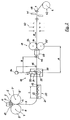
- Fig. 2 in Fig. 2 is shown schematically, the means 15 for the production of a strip of tape and thus the preference to the metal strip by a horizontally oriented belt support 20 is exercised, which brakes the cast over it over metal strip 3.
- This braking effect is generated by mounted in the roller table 21 of the belt support means 20 brake rollers 22, for which purpose a roller length L sufficient, which corresponds to 1.5 times to 2.5 times the bandwidth of the cast metal strip 3.
- the belt steering device 19 is equipped with adjustable metal belt transport means 26 formed by drive rollers 24, 25.
- the strip-deflecting device 19 is designed as a two-roller driver 27 and arranged in front of the rolling stand 18 in a distance A co-determined by the width of the cast metal strip 3. This distance A is in a range that is 1.0 times to 10.0 times the bandwidth.
- the scaffolding frame 28 of the band steering device 19 is supported on guides 29, which can be designed as sliding guides or roller guides, and is in the predetermined by a displacement device 30 which is designed as a pressure medium cylinder and on the one hand on the scaffolding frame 28 and on the other hand on the guides 29 Bandwidth-dependent position (distance A) brought.
- a braking force is exerted on the metal strip passing through the work rolls 32, 32 'of the rolling stand 18, which corresponds to a strip tension between 2.0 MPa and 15.0 MPa.
- the Bandlenkfunktion can be met with various Ausfatuhgsformen the band steering device 19 in conjunction with a Bandlagenmittenregelung.
- the adjustable drive pulley 24 is rotatably supported in a pivotable carrying device 33 and coupled to a corresponding setting and control device 34 and to a belt position measuring device 35 for its positioning.
- the tape layer measuring device 35 is disposed near the Bandienk worn 19 downstream of her. Positioning of the tape layer measuring device upstream of the belt line direction is also possible. The deviation of the metal strip from the predetermined strip center is detected with this band-layer measuring direction and a corresponding signal is transmitted to the setting and control device 34.
- the pivotal movement of the support means 33 by which an inclination of the axis 36 of a drive roller 24 in relation to the axis 37 of the further drive roller 25 (rotational adjustment in the arrow direction) or both propelled in a common support drive rollers (24, 25) in relation to the instantaneous tape travel direction by a maximum a few angular degrees is achieved, allows alignment of the cast metal strip 3 to the predetermined strip running direction R and thus ensures a central passage of the metal strip through the downstream roll stand 18th
- Fig. 2 an embodiment is schematically indicated, in which on the pivotable support means 33 of the drive roller 24 controllable contact forces are applied in the arrow direction, preferably in the region of the opposite bearing points of the drive roller in the pivotal support means 33.
- the transversely to the strip running direction R in the cast metal strip 3 inflowing transverse forces shift the tape running direction in the direction of these lateral forces.
- Fig. 3 shows a schematic representation of a preferred embodiment of the Bandienkelnraum 19.
- the drive rollers 24, 25 receiving scaffolding frame 28 is pivotally supported about curved, in particular arcuate guides 49 about a vertical axis 50 and by a pivoting device 51, for example, of hydraulic or electromechanical actuators, in particular is also formed with a coupling gear, adjustable in its orientation to the strip running direction R.
- the vertical axis 50 represents the instantaneous pole of the pivoting movement.
- the transverse forces or differential belt pulls acting on the metal strip thereby displace the strip running direction in the direction of these transverse forces.
- the tape steering device 19 is a tape position measuring device 35, e.g. an optical, capacitive or inductive measuring system assigned, which determines the actual position of the band edges or the band center of the metal band. The determined measurement results are fed to a control device from which control signals are delivered to the respective actuators of the strip deflection device.
- a tape position measuring device 35 e.g. an optical, capacitive or inductive measuring system assigned
- a belt running centering aid 46 is positioned downstream of the belt steering device 19 either in front of or behind the rolling stand 18. It forms a fixed point for the band guide and has an additional stabilizing effect on the strip running when the rolling stand 18 is closed.
- the tape-running centering aid 46 is shown schematically as a three roller driver and shown on the outlet side of the roll stand 18, in Fig. 2 the strip-running centering aid 46 is shown as a two-roller driver on the inlet side of the roll stand 18.
- the cast metal strip 3 is rolled with a reduction of up to 50% in an in-line rolling to a hot-rolled metal strip 1 with a predetermined Endbanddicke. Higher reduction rates and thus lower final strip thicknesses can be achieved when using multi-stand rolling mills.
- the roll stand 18 may be preceded by a temperature compensation zone 39, which is formed by a tunnel-shaped temperature compensation furnace or a strip edge heater. After leaving the roll stand 18, the metal strip 1 is cooled controlled in a cooling section 40, divided according to the desired coil weight with a dividing shear 41 and wound in a band coiler 42 to bundles 4.
- the roll gap 44 of the rolling stand 18 is open.
- the Anfahrstrang is separated with the dividing shear of cast metal strip and fed the metal strip of the coiler and wound.
- the work rolls 32, 32 'of the roll stand are moved together according to the desired roll gap 44 and the reel speed is adapted to the degree of deformation set in the roll stand.
- the stationary operating condition of the system is reached.
- the construction of the tape train and the Bandhaspelstrom 42 or its upstream inlet driver 48 are used. Any driver assembly positioned between the tape director 19 and the tape coiler can perform this function.
Landscapes
- Engineering & Computer Science (AREA)
- Mechanical Engineering (AREA)
- Metal Rolling (AREA)
- Continuous Casting (AREA)
- Control Of Metal Rolling (AREA)
Abstract
Description
- Die Erfindung betrifft ein Verfahren zur kontinuierlichen Herstellung eines gewalzten Metallbandes aus einer Metallschmelze, insbesondere eines Stahlbandes, wobei in einem ersten Herstellungsschritt Schmelze in eine Bandgießeinrichtung eingebracht und ein gegossenes Metallband mit vorgebarer Bandbreite aus dieser ausgefördert wird und in einem nachfolgenden zweiten Herstellungsschritt das gegossene unzerteilte Metallband in mindestens einem Walzgerüst auf Endbanddicke walzverformt wird, wobei die Positionierung des Metallbandes im Walzspalt durch eine dem Walzgerüst vorgelagerte Bandlenkung mittels einer Bandlenkennrichtung erfolgt. Die Erfindung betrifft weiters eine Anlage zur Durchführung dieses Verfahrens.
- Ein derartiges Verfahren und eine entsprechende Vorrichtunge zur Erzeugung eines gewalzten Stahlbandes aus einer Stahlschmelze, wobei ein dünnes Gussband nach dem Zweiwalzengießverfahren mit einer Zweiwalzengießvorrichtung erzeugt und in einem direkten Weiterverarbeitungsschritt in einem Walzgerüst unmittelbar aus der Gießhitze warmverformt wird, sind aus der
EP-B 540 610 EP-A 760 397 - Aus der
EP-B 540 610 - Aus der
EP-A 760 397 - dem Treibrollenpaar und dem Walzgerüst eine Tänzerrollen in einer Bandschlaufe zur Vermeidung eines mäanderförmigen Bandlaufes beim Eintritt in das Walzgerüst positioniert (
Fig. 3 ). Nach einer weiteren Ausführungsform sind zur Vermeidung des störenden Bandlaufs mehrere Lenk- oder Treibrollen im Abstand zueinander in einem temperaturkontrollierten Bereich vor dem Walzgerüst angeordnet und notwendig (Fig. 7). - Aus der
EP 903 187 A2 - Aufgabe der Erfindung ist es daher, diese beschriebenen Nachteile des Standes der Technik zu vermeiden und ein Verfahren und eine Vorrichtung vorzuschlagen, wodurch für das Metallband eingangsseitig des Walzgerüstes bzw. dem Ort der Walzverformung in Abhängigkeit von den Banddimensionen mit geringem Anlagenaufwand ein stabiler Bandeinlauf in das Walzgerüst gewährleistet ist.
- Diese Aufgabe wird bei einem Verfahren der eingangs genannten Art dadurch gelöst, dass die Bandlenkung im Abstand vom 1,0-fachen bis 10,0-fachen der Bandbreite, vorzugsweise im Abstand vom 1,5-fachen bis 5,0-fachen der Bandbreite, vor diesem Walzgerüst einwirkt bzw. durchgeführt wird wobei das gegossene Metallband eine Banddicke unter 20mm, vorzugsweise zwischen 1mm und 12mm, aufweist, und der Abstand der Banbdlenkeinrichtung (19) vom Walzgerüst (18) mittels Führungen, auf denen die Bandlenkeinrichtung (19) abgestützt ist, und mittels einer Verschiebeerinchtung (30) eingestellt wird. Es konnte ein grundsätzlicher Zusammenhang zwischen der Bandbreite des zu walzenden Metallbandes und dem optimalen Ort für den Einsatz der Bandlenkungsmaßnahmen insofern festgestellt werden, dass die Lenkungsmaßnahmen bei breiteren Bändern in größerem Abstand vor dem Walzgerüst vorgenommen werden können. Erfolgt die Bandlenkung zu Nahe am Walzgerüst, so muss ein instabiles Verhalten (z.B. Überschwingverhalten, Kantenüberdehnungen etc.) der Bandlenkung erwartet werden. Andererseits kommt es ebenfalls zu einem Verlaufen des Bandes, wenn die Maßnahmen zur Bandlenkung in zu großem Abstand vor dem Walzgerüst stattfinden. In diesem Fall gehen die Lenkungseffekte bereits vor Erreichen des Walzgerüstes wieder verloren.
- Ein optimaler Bandlauf stellt sich ein, wenn das Metallband in einem Bereich stromaufwärts des Walzgerüstes, zwischen einer Bandlenkeinrichtung und dem Walzspalt, unter einem Bandzug zwischen 2,0 MPa und 15 MPa, vorzugsweise zwischen 4,0 MPa und 8,0 MPa, gehalten wird. Ist der Bandzug zu gering, so kommt es zu einem Verlaufen des Bandes, z.B. durch einseitige Druckspannungen. Dies macht sich durch Instabilitäten, z.B. ein Flattern des Bandes, bemerkbar. Andererseits steigt mit zunehmendem Bandzug das Bandrissrisiko. Da die Bandtemperatur in diesem Bereich hoch gehalten wird, ist die Festigkeit des Metallbandes entsprechend geringer und damit auch die zulässige Andrückkraft, die auf das Metallband aufgebracht werden kann, ohne Eindrückungen der Treibrollen in ihm zu verursachen.
- Zur Durchführung einer präzisen Bandmittenlagenregelung ist es notwendig dass, vorzugsweise nahe dem Ort der Einwirkung der Bandlenkung auf das Metallband, die seitliche Ist-Abweichung des Metallbandes von der vorgegebenen Bandlaufrichtung erfasst und in Abhängigkeit davon die Position von Stellorganen der Bandienkeinrichtung geregelt wird.
- Eine zusätzliche Stabilisierung des Bandlaufes kann erreicht werden, wenn das Metallband in einem Bereich stromaufwärts der Bandlenkeinrichtung unter einem Bandvorzug gehalten wird. In diesem Bereich kann der Bandzug geringer gehalten werden, als im nachfolgenden Einlaufbereich des Walzgerüstes und dient vorwiegend der Beruhigung und Abstützung des aus der Gießmaschine austretenden Metallbandes. Vorzugsweise wird der Bandvorzug durch das Eigengewicht des in einer Schlingengrube durchhängenden Metallbandes erzeugt bzw. eingestellt. Alternativ hierzu kann der Bandvorzug durch eine der Bandlaufrichtung entgegengesetzt wirkende Bremskraft erzeugt bzw. eingestellt werden.
- Eine weitere Stabilisierung des Bandlaufes kann erreicht werden, wenn in einem Abstand vom Ort der Einwirkung der Bandlenkung, der dem 1,0-fachen bis 10,0-fachen der Bandbreite, vorzugsweise dem 1,5-fachen bis 5,0-fachen der Bandbreite, entspricht, vor oder nach dem Ort der Walzverformung, eine Bandlauf-Zentrierhilfe auf das Metallband einwirkt. Dies ist Insbesondere in den Betriebsphasen von Bedeutung, in denen das Walzgerüst offen ist, d.h. keine Walzverformung des Metallbandes stattfindet, insbesondere in der Anfahrphase des Produktionsablaufes. Gleichzeitig dient die Bandlauf-Zentrierhilfe als Fixpunkt für die Bandmittenlagenregelung, um trotz der geringen Bandzüge eine hinreichende Bandzentrierung realisieren zu können.
- Zur Erzeugung eines gegossenen Metallbandes mit einer Banddicke unter 20 mm, vorzugsweise zwischen 1 mm und 12 mm und eines in einem kontinuierlichen Herstellungsprozess erzeugten warmgewalzten Metallbandes wird weiters eine Anlage vorgeschlagen, bestehend aus einer Bandgießeinrichtung, vorzugsweise einer Zweiwaizengießmaschine und mindestens einem nachgeordneten Walzgerüst zur Inline-Walzumformung des gegossenen unzerteilten Metallbandes, sowie einer zwischen der Bandgießeinrichtung und dem Walzgerüst angeordneten Bandlenkeinrichtung. Diese Anlage ist dadurch gekennzeichnet, dass die Bandlenkeinrichtung dem Walzgerüst im Abstand vom 1,0-fachen bis 7,0-fachen der Bandbreite, vorzugsweise im Abstand vom 1,5-fachen bis 5,0-fachen der Bandbreite, vorgeordnet ist.
- Die Bandlenkeinrichtung ist auf Führungen abgestützt und zwischen Bandlenkeinrichtung und Führungen eine Verschiebeeinrichtung für die Bandlenkeinrichtung angeordnet. Die Führungen sind hierbei parallel zur Bandlaufrichtung ausgerichted. Vorzugsweise ist diese Bandlenkeinrichtung von einem Mehrrollentreiber, vorzugsweise von einem Zweirollentreiber gebildet.
- Eine vorteilhafte Weiterbildung dieser Anlage, mit den zuvor beschriebenen Vorteilen, ergibt sich, wenn in der Bandlenkeinrichtung Metallband-Transportmittel angeordnet sind, vorzugsweise die Treibrollen eines Mehrrollentreibers, die mit Anstell- und Regeleinrichtungen zusammenwirken und mittels welchen die Einstellung eines Bandzuges zwischen 2,0 MPa und 10 MPa, vorzugsweise zwischen 4,0 MPa und 7,0 MPa, zwischen der Bandlenkeinrichtung und dem Walzgerüst oder der Bandlauf-Zentrierhilfe oder einem sonstigen Aggregat in der Bandlauflinie vorgebbar ist.
- Ein optimales Einwirken auf den Bandlauf ist gegeben, wenn der Bandlenkeinrichtung eine Bandlagen-Messeinrichtung zugeordnet ist und in der Bandlenkeinrichtung Metaliband-Transportmittel angeordnet sind, vorzugsweise die Treibrollen eines Mehrrollentreibers, wobei mindestens eines der Metallband-Transportmittel in einer um eine Achse schwenkbaren Trageinrichtung drehbar abgestützt sind und diese mit Steuer- oder Regeleinrichtungen zur Beeinflussung der Bandlaufrichtung zusammenwirken. Die schwenkbare Achse ist vorzugsweise vertikal als Hochachse oder parallel zur Bandlaufrichtung ausgerichtet.
- Nach einer vorteilhaften Ausführungsform bildet die Bandlenkeinrichtung selbst die schwenkbare Trageinrichtung und diese ist auf Führungen verlagerbar abgestützt und mit einem Verstellantrieb verbunden, der vorzugsweise ein Koppelgetriebe ist. Andere mechanische, elektromechanische, hydraulische oder elektrohydraulische Antriebe sind ebenfalls möglich. Die Führungen können von Gelenkvierecken oder anderen kinematischen Getrieben, Schienen, Leisten, Rollen, etc, gebildet sein.
- Zur Erzielung eines optimalen Bandlaufes wird weiters vorgeschlagen, dass zwischen der Bandgießeinrichtung und der Bandlenkeinrichtung eine Einrichtung zur Erzeugung eines Bandvorzuges im Metallband angeordnet ist. Diese Einrichtung kann beispielsweise von einer Schlingengrube gebildet werden, wobei im wesentlichen die Länge der durchhängenden Schlaufe den Bandzug bestimmt. Zusätzlich wirkt die durchhängende Bandschlaufe als Dämpfungsglied zwischen der Zweiwalzengießeinrichtung und dem Walzgerüst, wodurch störende Rückkopplungen zwischen den abfolgenden Verfahrensschritten vermieden werden. Nach einer anderen Ausführungsform ist die Einrichtung zur Erzeugung eines Bandvorzuges von einer vorzugsweise horizontalen und reibungsbehafteten Bandstützeinrichtung, insbesondere einem Rollgang mit Bremsrollen, gebildet. Zwischen den Bremsrollen oder an deren Stelle können einfache, unbewegte, reibungsbehaftete mechanische Stützelemente vorgesehen sein. Hierbei bestimmt die Länge der Bandstützeinrichtung den Bandzug, wobei die wirksame Länge der Bandstützeinrichtung mindestens das 1,5-fache der Bandbreite, vorzugsweise mindestens das 2,5-fache der Bandbreite beträgt. Die wirksame Länge ist die Länge des mit Bremsrollen bestückten Rollganges.
- Zur Aufrechterhaltung der Lenkfunktion im Bereich des Walzgerüstes, insbesondere bei geöffnetem Walzspalt, wird vorgeschlagen, dass stromabwärts des Walzgerüstes oder zwischen der Bandlenkeinrichtung und dem Walzgerüst eine Bandlauf-Zentrierhilfe, vorzugsweise ein nicht lenkbarer Zwei- oder Dreirollentreiber, angeordnet ist. Die Bandlenkeinrichtung und die Bandlauf-Zentrierhilfe sind das 1,0-fache bis 10,0-fache der Bandbreite, vorzugsweise das 1,5-fache bis 5,0-fache der Bandbreite, voneinander entfernt angeordnet. Daraus folgt, dass das Walzgerüst und die Bandlenkeinrichtung zueinander sehr nahe positioniert sind, wenn die Bandlauf-Zentrierhilfe stromabwärts vom Walzgerüst steht und dass das Walzgerüst und die Bandlenkeinrichtung weiter voneinander entfernt sind, wenn die Bandlauf-Zentrlerhilfe stromaufwärts des Walzgerüstes steht.
- Um ein stabiles Hochfahren des Produktionsprozesses bzw. der Anlage während der Startphase zu gewährleisten wird wie folgt vorgegangen :
- Das die Bandgießeinrichtung verfassende, gegossene Metallband wird im wesentlichen mit einer der Gießgeschwindigkeit entsprechenden Bandlaufgeschwindigkeit, bei geöffnetem Walzspalt des Walzgerüstes durch die Anlage geführt und in die Bandhaspeleinrichtung eingefädelt,
- es wird ein geregelter Bandzug zwischen einer Bandlenkeinrichtung und einer dem Walzgerüst vorgeordneten Bandlauf-Zentrierhilfe oder einer dem Walzgerüst nachgeordneten Bandlauf-Zentrierhilfe oder der Bandhaspeleinrichtung eingestellt,
- gleichzeitig oder nachfolgend wird eine geregelte Bandlenkung in einem Abstand vor dem Walzgerüst zugeschaltet;
- die Arbeitswalzen des Walzgerüstes werden auf einen Walzspalt entsprechend der Bandenddicke eingestellt und
- die Walzgeschwindigkeit wird an die Gießgeschwindigkeit angepasst.
- Die geregelte Bandlenkung wird hierbei in einem Abstand, der dem 1,0-fachen bis 10,0-fachen der Bandbreite, vorzugsweise dem 1,5-fachen bis 5,0-fachen der Bandbreite des gegossenen Metallbandes entspricht, stromaufwärts des Walzgerüstes auf das sich unter Bandzug befindliche Metallband zugeschaltet. Verteilhaft wird der geregelte Bandzug zwischen der Bandlenkeinrichtung und der Bandhaspeleinrichtung oder einer Bandlauf-Zentrierhilfe auf einen Wert zwischen 2,0 MPa und 15 MPa, vorzugsweise zwischen 4,0 MPa und 8,0 MPa, gehalten. Dieser Bandzug wird bereits vor der Arbeitswalzenanstellung, d.h. vor Beginn des Walzvorganges, auf das gegossene Metallband aufgebracht und während des Walzvorganges aufrechterhalten.
- Weitere Vorteile und Merkmale der vorliegenden Erfindung ergeben sich aus der nachfolgenden Beschreibung nicht einschränkender Ausführungsbeispiele, wobei auf die beiliegenden Figuren Bezug genommen wird, die folgendes zeigen:
- Fig. 1
- eine schematische Darstellung der erfindungsgemäßen Anlage nach einer ersten Ausführungsform,
- Fig. 2
- eine schematische Darstellung der erfindungsgemäßen Anlage nach einer zweiten Ausführungsform.
- Fig.3
- eine bevorzugte Ausführungsform der erfindungsgemäßen Bandlenkeinrichtung.
- In den nachfolgend beschriebenen Ausführungsformen gemäß den
Figuren 1 bis 3 sind gleiche Bauteile mit identischen Bezugszeichen gekennzeichnet. - In den
Fig. 1 und2 ist eine erfindungsgemäße Anlage zur kontinuierlichen Herstellung eines gewalzten Metallbandes 1 aus einer Metallschmelze 2 dargestellt, wobei in einem ersten Produktionsschritt aus der Metallschmelze ein gegossenes Metallband 3 erzeugt wird und in einem zweiten direkt anschließenden Produktionsschritt das gegossene Metallband 3 einer Warmverformung in einem Walzprozess unterworfen wird. Das solcherart erzeugte gewalzte Metallband 1 wird anschließend, gegebenenfalls unter Zwischenschaltung eines gesteuerten Abkühlprozesses, der hier nicht näher beschrieben ist, zu Bunden 4 vorgegebenen Gewichtes gewickelt. - Zur Erzeugung des gegossenen Metallbandes mit einer Banddicke zwischen 1,0 und 20 mm wird eine Bandgießeinrichtung 5 eingesetzt, deren strangbildende Kerneinheit von einem einzelnen unterseitig horizontal laufenden Band oder mehreren umlaufenden Bändern, Raupen oder Kokillenwänden gebildet ist. In
Fig. 1 ist als eine mögliche Ausführungsform eine Zweiwalzengießmaschine 6 schematisch dargestellt, die von zwei um horizontale Achsen 7, 7' rotierenden Gießwalzen 8. 8' gebildet ist und zusammen mit stimseitig an die Gießwalzen angepressten Seitenwänden 9 einen Formhohlraum 10 für die Aufnahme der Metallschmelze 2 bildet, die über ein Zwischengefäß 11 zugeführt wird. Zwischen den Gießwalzen 8, 8' wird in einem schnell ablaufenden Erstarrungsprozess das gegossenen Metallband 3 in einem Gießspalt 12 gebildet und nach unten ausgefördet. Das gegossene Metallband 3 wird anschließend in die Horizontale umgelenkt und durchläuft eine von einer Schlingengrube 16 gebildeten Einrichtung 15 zur Erzeugung eines Bandvorzuges. Mit der in der Schlingengrube 16 durchhängenden Bandschlaufe 17 werden auch temporäre, produktionsbedingte Geschwindigkeitsunterschiede in Bandlauf zwischen Bandgießeinrichtung 5 und dem Walzgerüst 18 ausgeglichen. Durch die Länge der durchhängenden Bandschlaufe 17 wird ein leichter Vorzug auf das gegossene Metallband 3 ausgeübt und ein stabilisierter, gleichmäßiger Bandlauf zur nachgeordneten Bandlenkeinrichtung 19 gewährleistet. - Nach einer weiteren Ausführungsform, die in
Fig. 2 schematisch dargestellt ist, wird die Einrichtung 15 zur Erzeugung eines Bandvorzuges und damit der Vorzug auf das Metallband von einer horizontal ausgerichteten Bandstützeinrichtung 20 ausgeübt, die das darüber hinweggleitende gegossene Metallband 3 bremst. Diese Bremswirkung wird von im Rollgang 21 der Bandstützeinrichtung 20 gelagerten Bremsrollen 22 erzeugt, wobei hierfür eine Rollgangslänge L ausreicht, die der 1,5-fachen bis 2,5-fachen Bandbreite des gegossenen Metallbandes 3 entspricht. - Die Bandlenkeinrichtung 19 ist mit von Treibrollen 24, 25 gebildeten, verstellbaren Metallband-Transportmitteln 26 ausgestattet. Nach
Fig. 1 ist die Bandlenkeinrichtung 19 als Zweirollentreiber 27 ausgebildet und in einem von der Breite des gegossenen Metallbandes 3 mitbestimmten Abstand A vor dem Walzgerüst 18 angeordnet. Dieser Abstand A liegt in einem Bereich, der das 1,0-fache bis 10,0-fache der Bandbreite beträgt. Der Gerüstrahmen 28 der Bandlenkeinrichtung 19 ist auf Führungen 29, die als Gleitführungen oder Rollenführungen gestaltet sein können, abgestützt und wird von einer Verschiebeeinrichtung 30 , die als Druckmittelzylinder ausgebildet ist und die einerseits am Gerüstrahmen 28 und andererseits an den Führungen 29 angreift, in die vorbestimmte bandbreitenabhängige Position (Abstand A) gebracht. Weiters wird durch die Treibrollen 24, 25 des Zweirollentreibers 27 eine Bremskraft auf das die Arbeitswalzen 32, 32' des Walzgerüst 18 durchlaufende Metallband ausgeübt, die einem Bandzug zwischen 2,0 MPa und 15,0 MPa entspricht. - Die Bandlenkfunktion kann mit verschiedenen Ausführuhgsformen der Bandlenkeinrichtung 19 in Verbindung mit einer Bandlagenmittenregelung erfüllt werden.
- Nach der in
Fig. 1 dargestellten Ausführungsform ist die verstellbaretreibrolle 24 in einer schwenkbaren Trageinrichtung 33 drehbar abgestützt und mit einer entsprechenden Anstell-und Regeleinrichtung 34 und mit einer Bandlagen-Messeinrichtung 35 zu ihrer Positionierung gekoppelt. Die Bandlagen-Messeinrichtung 35 ist nahe der Bandienkeinrichtung 19 stromabwärts von ihr angeordnet. Eine Positionierung der Bandlagen-Messeinrichtung stromaufwärts der Bandienkelnrichtung ist ebenfalls möglich. Mit dieser Bandlagen-Messelnrichtung wird die Abweichung des Metallbandes von der vorgegebenen Bandlaufmitte erfasst und ein entsprechendes Signal an die Anstell- und Regeleinrichtung 34 übermittelt. Die Schwenkbewegung der Trageinrichtung 33, durch die eine Schrägstellung der Achse 36 einer Treibrolle 24 in Relation zur Achse 37 der weiteren Treibrolle 25 (Drehverstellung in Pfeilrichtung) oder beider in einer gemeinsamen Trageinrichtung abgestützen Treibrollen (24, 25) in Relation zur augenblicklichen Bandlaufrichtung um maximal einige wenige Winkelgrade erzielt wird, ermöglicht eine Ausrichtung des gegossenen Metallbandes 3 auf die vorgegebene Bandlaufrichtung R und gewährleistet damit ein mittiges Durchführen des Metallbandes durch das nachgeordneten Walzgerüst 18. - In
Fig. 2 ist eine Ausführungsform schematisch angedeutet, bei der auf die schwenkbare Trageinrichtung 33 der Treibrolle 24 regelbare Anpresskräfte in Pfeilrichtung aufgebracht werden, vorzugsweise im Bereich der gegenüberliegenden Lagerstellen der Treibrolle in der schwenkbaren Trageinrichtung 33. Die hierbei quer zur Bandlaufrichtung R in das gegossenen Metallband 3 einfließenden Querkräfte verlagern die Bandlaufrichtung in Richtung dieser Querkräfte. -
Fig. 3 zeigt in schematischer Darstellung eine bevorzugte Ausführungsform der Bandienkelnrichtung 19. Der die Treibrollen 24, 25 aufnehmende Gerüstrahmen 28 ist über gebogene, insbesondere kreisbogenförmige Führungen 49 um eine vertikale Achse 50 schwenkbar abgestützt und durch eine Verschwenkeinrichtung 51, die beispielsweise von hydraulischen oder elektromechanischen Betätigungseinrichtungen, insbesondere auch mit einem Koppelgetriebe, gebildet ist, in seiner Ausrichtung zur Bandlaufrichtung R einstellbar. Die vertikale Achse 50 stellt den Momentanpol der Schwenkbewegung dar. Die dadurch auf das Metallband einwirkenden Querkräfte bzw. Differenzbandzüge verlagern die Bandlaufrichtung in Richtung dieser Querkräfte. - Der Bandlenkeinrichtung 19 ist eine Bandlagen-Messeinrichtung 35, z.B. ein optisches, kapazitives oder induktives Messsystem, zugeordnet, die die ist-Lage der Bandkanten bzw. der Bandmitte des Metallbandes bestimmt. Die ermittelten Messergebnisse werden einer Regeleinrichtung zugeführt von der Steuersignale an die jeweiligen Stellorgane der Bandlenkeinrichtung abgegeben werden.
- Um trotz des geringen Bandzuges eine hinreichende Bandzentrierung realisieren zu können, ist eine Bandlaufzentrierhilfe 46 stromabwärts der Bandlenkeinrichtung 19 entweder vor oder hinter dem Walzgerüst 18 positioniert. Sie bildet einen Fixpunkt für die Bandlenkung und hat bei geschlossenem Walzgerüst 18 eine zusätzliche stabilisierende Wirkung auf den Bandlauf. In
Fig. 1 ist die Bandlauf-Zentrierhilfe 46 als Dreirollentreiber schematisch dargestellt und auslaufseitig des Walzgerüstes 18 dargestellt, inFig. 2 ist die Bandlauf-Zentrierhilfe 46 als Zweirollentreiber einlaufseitig des Walzgerüstes 18 dargestellt. - In einem Warmverformungsprozess, der im Walzgerüst 18 (Duo-, Quarto- oder Sextowalzwerk) erfolgt, wird das gegossene Metallband 3 mit einem Reduktionsgrad von bis zu 50% in einem inline-Walzvorgang zu einem warmgewalzten Metallband 1 mit vorbestimmter Endbanddicke gewalzt. Höhere Reduktionsgrade und damit geringere Endbanddicken sind bei Einsatz mehrgerüstiger Walzstraßen erzielbar. Zur Einstellung einer vorbestimmten gleichmäßigen Walztemperatur kann dem Walzgerüst 18 eine Temperaturausgleichszone 39 vorgeschalten sein, die von einem tunnelförmigen Temperaturausgleichsofen oder einer Bandkantenheizung gebildet ist. Nach Verlassen des Walzgerüstes 18 wird das Metallband 1 in einer Kühlstrecke 40 kontrolliert abgekühlt, entsprechend dem gewünschten Bundgewicht mit einer Querteilschere 41 zerteilt und in einer Bandhaspelanlage 42 zu Bunden 4 gewickelt.
- Während eines Anfahrvorganges, bei dem das erste Stück eines gegossenen Metallbandes bei Gießgeschwindigkeit mit, z.B., einem Anfahrstrang durch die Anlage gefädelt wird, ist der Walzspalt 44 des Walzgerüstes 18 offen. Der Anfahrstrang wird mit der Querteilschere von gegossenen Metallband getrennt und das Metallband der Haspelanlage zugeführt und angewickelt. Schon vor dem Anwickeln erfolgt der Aufbau eines Bandzuges, im speziellen zwischen der Bandlenkeinrichtung 19 und der Bandlauf-Zentrierhilfe 46 und gleichzeitig oder nachfolgend die Einstellung eines vorbestimmten Bandzuges. Im weiteren werden die Arbeitswalzen 32, 32' des Walzgerüstes entsprechend dem gewünschten Walzspalt 44 zusammengefahren und die Haspelgeschwindigkeit an den im Walzgerüst eingestellten Verformungsgrad angepasst. Damit ist der stationäre Betriebszustand der Anlage erreicht. Anstelle der Bandlauf-Zentrierhilfe 46 kann zum Aufbau des Bandzuges auch die Bandhaspelanlage 42 oder der ihr vorgelagerte Einlauftreiber 48 herangezogen werden. Jede zwischen der Bandlenkeinrichtung 19 und der Bandhaspelanlage positionierte Treiberanordnung kann diese Funktion erfüllen.
Claims (18)
- Verfahren zur kontinuierlichen Herstellung eines gewalzten Metallbandes (1) aus einer Metallschmelze (2), insbesondere eines Stahlbandes, wobei in einem ersten Herstellungsschritt Schmelze in eine Bandgießeinrichtung (5) eingebracht und ein gegossenes Metallband (3) mit vorgegebener Bandbreite aus dieser ausgefördert wird und in einem nachfolgenden zweiten Herstellungsschritt das gegossene unzerteilte Metallband in mindestens einem Walzgerüst (18) auf Endbanddicke walzverformt wird, wobei die Positionierung des Metallbandes im Walzspalt (44) durch eine dem Walzgerüst vorgelagerte Bandlenkung erfolgt, dadurch gekennzeichnet dass die Bandlenkung im Abstand, vom 1,0-fachen bis 10,0-fachen der Bandbreite, vorzugsweise dem 1,5-fachen bis 5,0-fachen der Bandbreite, vor diesem Wolzgerüst einwirkt bzw durchgeführt wird, wobei das gegossene Metallband eine Banddicke unter 20mm, vorzugsweise zwischen 1mm und 12mm aufweist, und
der Abstand der Bandlenkeinrichtung (19) vom Walzgerüst (18) mittels Führungen, auf denen die Bandlenkeinrichtung (19) obgestützt ist, und mittels einer Verchiebeeinrichtung (30) eingestellt wird. - Verfahren nach Anspruch 1, dadurch gekennzeichnet, dass das Metallband (3) in einem Bereich stromaufwärts des Walzgerüstes (18), zwischen der Bandlenkeinrichtung (19) und dem Walzspalt (44), unter einem Bandzug zwischen 2,0 MPa und 15 MPa, vorzugsweise zwischen 4,0 MPa und 8,0 MPa, gehalten wird.
- Verfahren nach einem der vorhergehenden Ansprüche, dadurch gekennzeichnet, dass vorzugsweise nahe dem Ort der Einwirkung der Bandlenkung auf das Metallband die seitliche Ist-Abweichung des Metallbandes von der vorgegebenen Bandlaufrichtung erfasst und in Abhängigkeit davon die Position von Stellorganen der Bandlenkeinrichtung (19) geregelt wird.
- Verfahren nach einem der vorhergehenden Ansprüche, dadurch gekennzeichnet, dass das Metallband (3) in einem Bereich stromaufwärts der Bandlenkeinrichtung (19) unter einem Bandvorzug gehalten wird.
- Verfahren nach Anspruch 4, dadurch gekennzeichnet, dass der Bandvorzug durch das Eigengewicht des in einer Schlingengrube (16) durchhängenden Metallbandes (3) erzeugt bzw. eingestellt wird.
- Verfahren nach Anspruch 4, dadurch gekennzeichnet, dass der Bandvorzug durch eine der Bandlaufrichtung (R) entgegengesetzt wirkende Bremskraft erzeugt bzw. eingestellt wird.
- Verfahren nach einem der vorhergehenden Ansprüche, dadurch gekennzeichnet, dass in einem Abstand (B) vom Ort der Einwirkung der Bandlenkung, der dem 1,0-fachen bis 10-fachen der Bandbreite, vorzugsweise dem 1,5-fachen bis 5,0-fachen der Bandbreite, entspricht, eine Bandlauf-Zentrierhilfe (46), insbesondere bei offenem Walzgerüst (18), vor oder nach dem Ort der Walzverformung einwirkt.
- Anlage zur kontinuierlichen Herstellung eines gewalzten Metallbandes (1), insbesondere eines Stahlbandes, bestehend aus einer Bandgießeinrichtung (5), vorzugsweise einer Zweiwalzengießmaschine (6), zur Erzeugung eines gegossenen Metallbandes (3) mit einer Banddicke unter 20 mm, vorzugsweise zwischen 1 mm und 12 mm, und mindestens einem nachgeordneten Walzgerüst (18) zur Inline-Walzumformung des gegossenen unzerteilten Metallbandes, sowie einer zwischen der Bandgießeinrichtung (5) und dem Walzgerüst (18) angeordneten Bandlenkeinrichtung (19), dadurch gekennzeichnet, dass die Bandlenkeinrichtung (19) dem Walzgerüst (18) im Abstand (A) vom 1,0-fachen bis 10,0-fachen der Bandbreite, vorzugsweise im Abstand vom 1,5-fachen bis 5,0-fachen der Bandbreite, vorgeordnet ist, die Bandlenkeinrichtung (19) auf Führungen (29) abgestützt ist und zwischen Bandlenkeinrichtung (19) und Führungen (29) eine Verschiebeeinrichtung (30) für die Bandlenkeinrichtung (19) zur Einstellung des Abstandes vom Walzgerüst (18) angeordnet ist
- Anlage nach Anspruch 8, dadurch gekennzeichnet, dass die Bandlenkeinrichtung (19) von einem Mehrrollentreiber, vorzugsweise von einem Zweirollentreiber (27), gebildet ist.
- Anlage nach Anspruch 8 oder 9, dadurch gekennzeichnet, dass in der Bandlenkeinrichtung (19) Metallband-Transportmittel (26) angeordnet sind, vorzugsweise die Treibrollen (24, 25) eines Mehrrollentreibers, die mit Anstell- und Regeleinrichtungen (34) zusammenwirken und mittels welchen die Einstellung eines Bandzuges zwischen 2,0 MPa und 15 MPa, vorzugsweise zwischen 4,0 MPa und 8,0 MPa, zwischen der Bandlenkeinrichtung (19) und dem Walzgerüst (18) oder der Bandlauf-Zentrierhilfe (46) oder einem sonstigen Aggregat der Bandlauflinie vorgebbar ist.
- Anlage nach einen der Ansprüche 8 bis 10, dadurch gekennzeichnet, dass der Bandlenkeinrichtung (19) eine Bandlagen-Messeinrichtung (35) zugeordnet ist und dass in der Bandlenkeinrichtung (19) Metallband- Transportmittel (26) angeordnet sind, vorzugsweise die Treibrollen (24, 25) eines Mehrrollentreibers, wobei mindestens eines der Metallband-Transportmittel (26) in einer schwenkbaren Trageinrichtung (33) drehbar abgestützt sind und diese mit Steuer- oder Regeleinrichtungen (34) zur Beeinflussung der Bandlaufrichtung (R) zusammenwirken.
- Anlage nach Anspruch 11, dadurch gekennzeichnet, dass die Bandlenkeinrichtung (19) die schwenkbare Trageinrichtung (33) bildet und diese auf vorzugsweise bogenförmigen Führungen (49) verlagerbar abgestützt und mit einem Verstellantrieb (51), vorzugsweise einem Koppelgetriebe, verbunden ist.
- Anlage nach einem der Ansprüche 8 bis 12, dadurch gekennzeichnet, dass zwischen der Bandgießeinrichtung (5) und der Bandlenkeinrichtung (19) eine Einrichtung (15) zur Erzeugung eines Bandvorzuges im Metallband (3) angeordnet ist.
- Anlage nach Anspruch 13, dadurch gekennzeichnet, dass die Einrichtung (15) zur Erzeugung eines Bandvorzuges von einer Schlingengrube (16) gebildet ist.
- Anlage nach Anspruch 13, dadurch gekennzeichnet, dass die Einrichtung (15) zur Erzeugung eines Bandvorzuges von einer vorzugsweise horizontalen und reibungsbehafteten Bandstützeinrichtung (20), insbesondere einem Rollgang (21) mit Bremsrollen (22), gebildet ist.
- Anlage nach Anspruch 15, dadurch gekennzeichnet, dass die wirksame Länge (L) der Bandstützeinrichtung (20) mindestens das 1,5-fache der Bandbreite, vorzugsweise mindestens das 2,5-fache der Bandbreite aufweist.
- Anlage nach einem der Ansprüche 8 bis 16, dadurch gekennzeichnet, dass stromabwärts des Walzgerüstes (18) oder zwischen der Bandlenkeinrichtung (19) und dem Walzgerüst (19) eine Bandlauf-Zentrierhilfe (46), vorzugsweise ein nicht lenkbarer Zwei- oder Dreirollentreiber, angeordnet ist.
- Anlage nach Anspruch 17, dadurch gekennzeichnet, dass die Bandlenkeinrichtung (19) und die Bandlauf-Zentrierhilfe (46) im Abstand (B) vom 1,0-fachen bis 10,0-fachen der Bandbreite, vorzugsweise im Abstand vom 1,5-fachen bis 5,0-fachen der Bandbreite, voneinander entfernt angeordnet sind.
Applications Claiming Priority (3)
| Application Number | Priority Date | Filing Date | Title |
|---|---|---|---|
| AT16892001 | 2001-10-24 | ||
| AT0168901A AT410767B (de) | 2001-10-24 | 2001-10-24 | Verfahren und vorrichtung zur kontinuierlichen herstellung eines gewalzten metallbandes aus einermetallschmelze |
| PCT/EP2002/011406 WO2003035291A1 (de) | 2001-10-24 | 2002-10-11 | Verfahren und vorrichtung zur kontinuierlichen herstellung eines gewalzten metallbandes aus einer metallsschmelze |
Publications (2)
| Publication Number | Publication Date |
|---|---|
| EP1446242A1 EP1446242A1 (de) | 2004-08-18 |
| EP1446242B1 true EP1446242B1 (de) | 2009-12-02 |
Family
ID=3688666
Family Applications (1)
| Application Number | Title | Priority Date | Filing Date |
|---|---|---|---|
| EP02781241A Expired - Lifetime EP1446242B1 (de) | 2001-10-24 | 2002-10-11 | Verfahren und vorrichtung zur kontinuierlichen herstellung eines gewalzten metallbandes aus einer metallschmelze |
Country Status (17)
| Country | Link |
|---|---|
| US (2) | US6973956B2 (de) |
| EP (1) | EP1446242B1 (de) |
| JP (1) | JP2005506202A (de) |
| KR (1) | KR100879847B1 (de) |
| CN (1) | CN1272118C (de) |
| AT (2) | AT410767B (de) |
| AU (1) | AU2002349346B2 (de) |
| BR (1) | BR0213544B1 (de) |
| CA (1) | CA2463962C (de) |
| DE (1) | DE50214057D1 (de) |
| ES (1) | ES2336434T3 (de) |
| MX (1) | MXPA04003757A (de) |
| RU (1) | RU2293618C2 (de) |
| TW (1) | TWI226267B (de) |
| UA (1) | UA80956C2 (de) |
| WO (1) | WO2003035291A1 (de) |
| ZA (1) | ZA200402699B (de) |
Families Citing this family (16)
| Publication number | Priority date | Publication date | Assignee | Title |
|---|---|---|---|---|
| AT501314B1 (de) | 2004-10-13 | 2012-03-15 | Voest Alpine Ind Anlagen | Verfahren und vorrichtung zum kontinuierlichen herstellen eines dünnen metallbandes |
| US7163047B2 (en) * | 2005-03-21 | 2007-01-16 | Nucor Corporation | Pinch roll apparatus and method for operating the same |
| DE102006001195A1 (de) * | 2006-01-10 | 2007-07-12 | Sms Demag Ag | Verfahren zum Gieß-Walzen mit erhöhter Gießgeschwindigkeit und daran anschließendem Warmwalzen von relativ dünnen Metall-,insbesondere Stahlwerkstoff-Strängen,und Gieß-Walz-Einrichtung |
| DE102006035008A1 (de) * | 2006-07-28 | 2008-01-31 | Siemens Ag | Betriebsverfahren für einen Schlingenspeicher mit Zugausgleich |
| CN100450653C (zh) * | 2006-11-28 | 2009-01-14 | 中冶南方工程技术有限公司 | 防止0.4mm以下的薄板高速轧制工况下带钢颤动的方法 |
| US8141618B2 (en) * | 2008-06-24 | 2012-03-27 | Nucor Corporation | Strip casting method for controlling edge quality and apparatus therefor |
| PL2340133T5 (pl) | 2008-10-30 | 2024-12-02 | Primetals Technologies Germany Gmbh | Sposób nastawiania obciążenia napędów dla pewnej liczby napędów walcowni do walcowania materiału walcowanego, zespół sterowania i/lub regulacji, nośnik pamięci, kod programowy i instalacja walcownicza |
| US20100215981A1 (en) * | 2009-02-20 | 2010-08-26 | Nucor Corporation | Hot rolled thin cast strip product and method for making the same |
| CN102320000B (zh) * | 2011-07-08 | 2013-01-30 | 邢台纳科诺尔极片轧制设备有限公司 | 一种电池极片碾压分切系统 |
| CN103376768B (zh) * | 2012-04-28 | 2016-10-05 | 宝山钢铁股份有限公司 | 一种大侧压机多设备协调控制方法 |
| CN108941216A (zh) * | 2018-08-20 | 2018-12-07 | 首钢京唐钢铁联合有限责任公司 | 一种侧导板动态对中方法、装置及系统 |
| CN109093203A (zh) * | 2018-09-25 | 2018-12-28 | 大连翼方科技有限公司 | 一种板材制造机及方法 |
| CN109622614A (zh) * | 2019-01-02 | 2019-04-16 | 重庆美丽彩实业(集团)有限公司 | 一种新型冷轧装置 |
| EP3974074B1 (de) * | 2019-07-11 | 2023-12-27 | Primetals Technologies Japan, Ltd. | Steuervorrichtung für eine walzvorrichtung, walzvorrichtung und verfahren zum betrieb einer walzvorrichtung |
| CN110586662B (zh) * | 2019-09-03 | 2024-02-06 | 石横特钢集团有限公司 | 一种棒材全流程控轧控冷生产线 |
| CN112828043B (zh) * | 2020-12-24 | 2023-05-23 | 舞阳钢铁有限责任公司 | 大厚度超宽低Si合金钢板的生产方法 |
Citations (2)
| Publication number | Priority date | Publication date | Assignee | Title |
|---|---|---|---|---|
| JPH08294715A (ja) * | 1995-04-21 | 1996-11-12 | Nippon Steel Corp | ストリップ連続鋳造熱間圧延熱処理設備およびストリップ連続鋳造熱間圧延熱処理方法 |
| EP0903187A2 (de) * | 1997-09-19 | 1999-03-24 | Ishikawajima-Harima Heavy Industries Co., Ltd. | Bandsteuerung |
Family Cites Families (9)
| Publication number | Priority date | Publication date | Assignee | Title |
|---|---|---|---|---|
| GB9016142D0 (en) * | 1990-07-23 | 1990-09-05 | Davy Distington Ltd | Method of manufacturing metal strip |
| US5503217A (en) * | 1990-07-23 | 1996-04-02 | Davy Mckee (Sheffield) Limited | Method of manufacturing metal strip |
| JP2828411B2 (ja) * | 1995-02-01 | 1998-11-25 | 新日本製鐵株式会社 | 薄鋳片の蛇行修正方法及び装置 |
| DE69623210T2 (de) * | 1995-04-14 | 2003-04-30 | Nippon Steel Corp., Tokio/Tokyo | Vorrichtung zur herstellung rostfreier stahlbänder |
| EP0760397B1 (de) * | 1995-04-14 | 2002-08-28 | Nippon Steel Corporation | Vorrichtung zur herstellung rostfreier stahlbänder |
| JP2750096B2 (ja) | 1995-05-08 | 1998-05-13 | 新日本製鐵株式会社 | ストリップ連続鋳造熱間圧延熱処理酸洗設備および酸洗コイルの製造方法 |
| IT1296715B1 (it) * | 1997-11-11 | 1999-07-15 | Danieli Off Mecc | Procedimento di controllo assialita' per bramme uscenti da colata continua e relativo dispositivo |
| RU2146974C1 (ru) * | 1998-05-21 | 2000-03-27 | Магнитогорская государственная горно-металлургическая академия им.Г.И.Носова | Способ производства бесконечной горячекатаной полосы на непрерывно-реверсивном литейно-прокатном агрегате |
| AUPQ546900A0 (en) * | 2000-02-07 | 2000-03-02 | Bhp Steel (Jla) Pty Limited | Rolling strip material |
-
2001
- 2001-10-24 AT AT0168901A patent/AT410767B/de not_active IP Right Cessation
-
2002
- 2002-10-11 CN CNB028212487A patent/CN1272118C/zh not_active Expired - Fee Related
- 2002-10-11 AU AU2002349346A patent/AU2002349346B2/en not_active Ceased
- 2002-10-11 MX MXPA04003757A patent/MXPA04003757A/es active IP Right Grant
- 2002-10-11 KR KR1020047005981A patent/KR100879847B1/ko not_active Expired - Lifetime
- 2002-10-11 WO PCT/EP2002/011406 patent/WO2003035291A1/de not_active Ceased
- 2002-10-11 DE DE50214057T patent/DE50214057D1/de not_active Expired - Lifetime
- 2002-10-11 EP EP02781241A patent/EP1446242B1/de not_active Expired - Lifetime
- 2002-10-11 CA CA2463962A patent/CA2463962C/en not_active Expired - Fee Related
- 2002-10-11 BR BRPI0213544-2A patent/BR0213544B1/pt not_active IP Right Cessation
- 2002-10-11 US US10/493,614 patent/US6973956B2/en not_active Expired - Lifetime
- 2002-10-11 JP JP2003537843A patent/JP2005506202A/ja active Pending
- 2002-10-11 AT AT02781241T patent/ATE450323T1/de active
- 2002-10-11 ES ES02781241T patent/ES2336434T3/es not_active Expired - Lifetime
- 2002-10-11 RU RU2004115622/02A patent/RU2293618C2/ru not_active IP Right Cessation
- 2002-10-15 TW TW091123631A patent/TWI226267B/zh not_active IP Right Cessation
- 2002-11-10 UA UA20040503828A patent/UA80956C2/uk unknown
-
2004
- 2004-04-06 ZA ZA200402699A patent/ZA200402699B/en unknown
-
2005
- 2005-08-15 US US11/203,777 patent/US20060010679A1/en not_active Abandoned
Patent Citations (2)
| Publication number | Priority date | Publication date | Assignee | Title |
|---|---|---|---|---|
| JPH08294715A (ja) * | 1995-04-21 | 1996-11-12 | Nippon Steel Corp | ストリップ連続鋳造熱間圧延熱処理設備およびストリップ連続鋳造熱間圧延熱処理方法 |
| EP0903187A2 (de) * | 1997-09-19 | 1999-03-24 | Ishikawajima-Harima Heavy Industries Co., Ltd. | Bandsteuerung |
Also Published As
| Publication number | Publication date |
|---|---|
| US20060010679A1 (en) | 2006-01-19 |
| AU2002349346B2 (en) | 2007-10-11 |
| RU2293618C2 (ru) | 2007-02-20 |
| AT410767B (de) | 2003-07-25 |
| MXPA04003757A (es) | 2004-07-23 |
| CN1272118C (zh) | 2006-08-30 |
| TWI226267B (en) | 2005-01-11 |
| KR20040045909A (ko) | 2004-06-02 |
| KR100879847B1 (ko) | 2009-01-22 |
| JP2005506202A (ja) | 2005-03-03 |
| UA80956C2 (en) | 2007-11-26 |
| CA2463962A1 (en) | 2003-05-01 |
| DE50214057D1 (de) | 2010-01-14 |
| ATE450323T1 (de) | 2009-12-15 |
| BR0213544B1 (pt) | 2010-11-30 |
| RU2004115622A (ru) | 2005-06-10 |
| US6973956B2 (en) | 2005-12-13 |
| US20050082030A1 (en) | 2005-04-21 |
| EP1446242A1 (de) | 2004-08-18 |
| WO2003035291A1 (de) | 2003-05-01 |
| ATA16892001A (de) | 2002-12-15 |
| ES2336434T3 (es) | 2010-04-13 |
| ZA200402699B (en) | 2005-04-06 |
| CN1575212A (zh) | 2005-02-02 |
| BR0213544A (pt) | 2004-10-26 |
| CA2463962C (en) | 2010-12-07 |
Similar Documents
| Publication | Publication Date | Title |
|---|---|---|
| EP0889762B1 (de) | Verfahren zur herstellung von warmgewalztem stahlband | |
| EP0611610B1 (de) | Verfahren zum Herstellen eines Bandes, Vorstreifens oder einer Bramme | |
| DE69202088T2 (de) | Vorrichtung und Verfahren zur Herstellung von warmgewalztem Stahl. | |
| AT410767B (de) | Verfahren und vorrichtung zur kontinuierlichen herstellung eines gewalzten metallbandes aus einermetallschmelze | |
| EP1406735B1 (de) | Kaltwalzerk sowie verfahren zum kaltwalzen von metallischem band | |
| EP3535076B1 (de) | Giess-walz-verbundanlage und verfahren zur endlosen herstellung eines warmgewalzten fertigbandes | |
| EP2603337B1 (de) | Verfahren zum herstellen von walzgut mittels einer giesswalzverbundanlage, steuer- und/oder regeleinrichtung für eine giesswalzverbundanlage und giesswalzverbundanlage | |
| EP0415987A1 (de) | Verfahren zur kontinuierlichen herstellung von bandstahl oder stahlblech aus nach dem bogenstranggiessverfahren hergestellten flachprodukten. | |
| EP2964404B1 (de) | Verfahren zum herstellen eines metallbandes durch giesswalzen | |
| DE102007056192A1 (de) | Verfahren und Vorrichtung zum Herstellen eines Bandes aus Metall | |
| EP0906797A1 (de) | Verfahren und Anlage zum Umformen von Metallband in einer Warmbandwalzanlage | |
| EP1071529B1 (de) | Verfahren zum stranggiessen von dünnen metallbändern | |
| WO2016165933A1 (de) | GIEß-WALZ-ANLAGE UND VERFAHREN ZU DEREN BETRIEB | |
| EP2864062B1 (de) | Verfahren zur gezielten beeinflussung der geometrie eines walzguts | |
| EP1784266B1 (de) | Walzwerk zum walzen von metallischem band | |
| DE3822939C1 (en) | Continuous casting method for the production of slabs with a reduced thickness relative to the cast condition | |
| WO2014056681A1 (de) | Breitenbeeinflussung eines bandförmigen walzguts | |
| EP0721813B1 (de) | Vorrichtung zum Führen von warmgewalztem Band durch einen Induktor | |
| DE1934302A1 (de) | Verfahren und Vorrichtung zum Warmwalzen von Metallbrammen | |
| EP1960136A1 (de) | Verfahren zum stranggiessen dünner metallbänder und stranggiessanlage | |
| EP1385656B1 (de) | Verfahren zum stranggiessen von blöcken, brammen oder dünnbrammen | |
| EP1289687A1 (de) | Verfahren und anlage zur herstellung eines metallbandes | |
| EP2869945A2 (de) | Kontinuierlich arbeitende bandgiess- und walzanlage | |
| EP1669141B1 (de) | Verfahren zur Regelung des Querschnitts von aus einer Drahtwalzstrasse austretenden Drähten und Drahtwalzstrasse | |
| EP3873685B1 (de) | Walzlinie |
Legal Events
| Date | Code | Title | Description |
|---|---|---|---|
| PUAI | Public reference made under article 153(3) epc to a published international application that has entered the european phase |
Free format text: ORIGINAL CODE: 0009012 |
|
| 17P | Request for examination filed |
Effective date: 20040402 |
|
| AK | Designated contracting states |
Kind code of ref document: A1 Designated state(s): AT BE BG CH CY CZ DE DK EE ES FI FR GB GR IE IT LI LU MC NL PT SE SK TR |
|
| AX | Request for extension of the european patent |
Extension state: AL LT LV MK RO SI |
|
| 17Q | First examination report despatched |
Effective date: 20050321 |
|
| APBN | Date of receipt of notice of appeal recorded |
Free format text: ORIGINAL CODE: EPIDOSNNOA2E |
|
| APBR | Date of receipt of statement of grounds of appeal recorded |
Free format text: ORIGINAL CODE: EPIDOSNNOA3E |
|
| APAF | Appeal reference modified |
Free format text: ORIGINAL CODE: EPIDOSCREFNE |
|
| RAP1 | Party data changed (applicant data changed or rights of an application transferred) |
Owner name: SIEMENS VAI METALS TECHNOLOGIES GMBH & CO |
|
| RIN1 | Information on inventor provided before grant (corrected) |
Inventor name: ECKERSTORFER, GERALD Inventor name: HOHENBICHLER, GERALD |
|
| APBT | Appeal procedure closed |
Free format text: ORIGINAL CODE: EPIDOSNNOA9E |
|
| GRAP | Despatch of communication of intention to grant a patent |
Free format text: ORIGINAL CODE: EPIDOSNIGR1 |
|
| GRAS | Grant fee paid |
Free format text: ORIGINAL CODE: EPIDOSNIGR3 |
|
| GRAA | (expected) grant |
Free format text: ORIGINAL CODE: 0009210 |
|
| AK | Designated contracting states |
Kind code of ref document: B1 Designated state(s): AT BE BG CH CY CZ DE DK EE ES FI FR GB GR IE IT LI LU MC NL PT SE SK TR |
|
| AX | Request for extension of the european patent |
Extension state: RO SI |
|
| REG | Reference to a national code |
Ref country code: GB Ref legal event code: FG4D Free format text: NOT ENGLISH |
|
| REG | Reference to a national code |
Ref country code: CH Ref legal event code: EP |
|
| REG | Reference to a national code |
Ref country code: IE Ref legal event code: FG4D |
|
| REF | Corresponds to: |
Ref document number: 50214057 Country of ref document: DE Date of ref document: 20100114 Kind code of ref document: P |
|
| REG | Reference to a national code |
Ref country code: SE Ref legal event code: TRGR |
|
| REG | Reference to a national code |
Ref country code: NL Ref legal event code: T3 |
|
| REG | Reference to a national code |
Ref country code: ES Ref legal event code: FG2A Ref document number: 2336434 Country of ref document: ES Kind code of ref document: T3 |
|
| PG25 | Lapsed in a contracting state [announced via postgrant information from national office to epo] |
Ref country code: CY Free format text: LAPSE BECAUSE OF FAILURE TO SUBMIT A TRANSLATION OF THE DESCRIPTION OR TO PAY THE FEE WITHIN THE PRESCRIBED TIME-LIMIT Effective date: 20091202 |
|
| REG | Reference to a national code |
Ref country code: IE Ref legal event code: FD4D |
|
| PG25 | Lapsed in a contracting state [announced via postgrant information from national office to epo] |
Ref country code: IE Free format text: LAPSE BECAUSE OF FAILURE TO SUBMIT A TRANSLATION OF THE DESCRIPTION OR TO PAY THE FEE WITHIN THE PRESCRIBED TIME-LIMIT Effective date: 20091202 Ref country code: EE Free format text: LAPSE BECAUSE OF FAILURE TO SUBMIT A TRANSLATION OF THE DESCRIPTION OR TO PAY THE FEE WITHIN THE PRESCRIBED TIME-LIMIT Effective date: 20091202 |
|
| PG25 | Lapsed in a contracting state [announced via postgrant information from national office to epo] |
Ref country code: SK Free format text: LAPSE BECAUSE OF FAILURE TO SUBMIT A TRANSLATION OF THE DESCRIPTION OR TO PAY THE FEE WITHIN THE PRESCRIBED TIME-LIMIT Effective date: 20091202 Ref country code: CZ Free format text: LAPSE BECAUSE OF FAILURE TO SUBMIT A TRANSLATION OF THE DESCRIPTION OR TO PAY THE FEE WITHIN THE PRESCRIBED TIME-LIMIT Effective date: 20091202 |
|
| PLBE | No opposition filed within time limit |
Free format text: ORIGINAL CODE: 0009261 |
|
| STAA | Information on the status of an ep patent application or granted ep patent |
Free format text: STATUS: NO OPPOSITION FILED WITHIN TIME LIMIT |
|
| PG25 | Lapsed in a contracting state [announced via postgrant information from national office to epo] |
Ref country code: GR Free format text: LAPSE BECAUSE OF FAILURE TO SUBMIT A TRANSLATION OF THE DESCRIPTION OR TO PAY THE FEE WITHIN THE PRESCRIBED TIME-LIMIT Effective date: 20100303 |
|
| 26N | No opposition filed |
Effective date: 20100903 |
|
| PG25 | Lapsed in a contracting state [announced via postgrant information from national office to epo] |
Ref country code: DK Free format text: LAPSE BECAUSE OF FAILURE TO SUBMIT A TRANSLATION OF THE DESCRIPTION OR TO PAY THE FEE WITHIN THE PRESCRIBED TIME-LIMIT Effective date: 20091202 |
|
| PGFP | Annual fee paid to national office [announced via postgrant information from national office to epo] |
Ref country code: AT Payment date: 20100915 Year of fee payment: 9 |
|
| PG25 | Lapsed in a contracting state [announced via postgrant information from national office to epo] |
Ref country code: MC Free format text: LAPSE BECAUSE OF NON-PAYMENT OF DUE FEES Effective date: 20101031 |
|
| REG | Reference to a national code |
Ref country code: CH Ref legal event code: PL |
|
| GBPC | Gb: european patent ceased through non-payment of renewal fee |
Effective date: 20101011 |
|
| PG25 | Lapsed in a contracting state [announced via postgrant information from national office to epo] |
Ref country code: CH Free format text: LAPSE BECAUSE OF NON-PAYMENT OF DUE FEES Effective date: 20101031 Ref country code: LI Free format text: LAPSE BECAUSE OF NON-PAYMENT OF DUE FEES Effective date: 20101031 |
|
| PG25 | Lapsed in a contracting state [announced via postgrant information from national office to epo] |
Ref country code: GB Free format text: LAPSE BECAUSE OF NON-PAYMENT OF DUE FEES Effective date: 20101011 |
|
| PGFP | Annual fee paid to national office [announced via postgrant information from national office to epo] |
Ref country code: TR Payment date: 20110927 Year of fee payment: 10 |
|
| PGFP | Annual fee paid to national office [announced via postgrant information from national office to epo] |
Ref country code: NL Payment date: 20111020 Year of fee payment: 10 Ref country code: SE Payment date: 20111020 Year of fee payment: 10 Ref country code: LU Payment date: 20111024 Year of fee payment: 10 Ref country code: FR Payment date: 20111024 Year of fee payment: 10 Ref country code: FI Payment date: 20111013 Year of fee payment: 10 Ref country code: ES Payment date: 20111108 Year of fee payment: 10 Ref country code: BG Payment date: 20111013 Year of fee payment: 10 |
|
| PGFP | Annual fee paid to national office [announced via postgrant information from national office to epo] |
Ref country code: BE Payment date: 20111110 Year of fee payment: 10 |
|
| REG | Reference to a national code |
Ref country code: AT Ref legal event code: MM01 Ref document number: 450323 Country of ref document: AT Kind code of ref document: T Effective date: 20111011 |
|
| PG25 | Lapsed in a contracting state [announced via postgrant information from national office to epo] |
Ref country code: AT Free format text: LAPSE BECAUSE OF NON-PAYMENT OF DUE FEES Effective date: 20111011 |
|
| BERE | Be: lapsed |
Owner name: SIEMENS VAI METALS TECHNOLOGIES GMBH & CO Effective date: 20121031 |
|
| REG | Reference to a national code |
Ref country code: NL Ref legal event code: V1 Effective date: 20130501 |
|
| REG | Reference to a national code |
Ref country code: FR Ref legal event code: ST Effective date: 20130628 |
|
| PG25 | Lapsed in a contracting state [announced via postgrant information from national office to epo] |
Ref country code: SE Free format text: LAPSE BECAUSE OF NON-PAYMENT OF DUE FEES Effective date: 20121012 Ref country code: BE Free format text: LAPSE BECAUSE OF NON-PAYMENT OF DUE FEES Effective date: 20121031 |
|
| PG25 | Lapsed in a contracting state [announced via postgrant information from national office to epo] |
Ref country code: NL Free format text: LAPSE BECAUSE OF NON-PAYMENT OF DUE FEES Effective date: 20130501 Ref country code: FI Free format text: LAPSE BECAUSE OF NON-PAYMENT OF DUE FEES Effective date: 20121011 Ref country code: FR Free format text: LAPSE BECAUSE OF NON-PAYMENT OF DUE FEES Effective date: 20121031 |
|
| REG | Reference to a national code |
Ref country code: ES Ref legal event code: FD2A Effective date: 20140116 |
|
| PGFP | Annual fee paid to national office [announced via postgrant information from national office to epo] |
Ref country code: IT Payment date: 20131029 Year of fee payment: 12 |
|
| PG25 | Lapsed in a contracting state [announced via postgrant information from national office to epo] |
Ref country code: TR Free format text: LAPSE BECAUSE OF NON-PAYMENT OF DUE FEES Effective date: 20121011 Ref country code: LU Free format text: LAPSE BECAUSE OF NON-PAYMENT OF DUE FEES Effective date: 20121011 Ref country code: ES Free format text: LAPSE BECAUSE OF NON-PAYMENT OF DUE FEES Effective date: 20121012 |
|
| PG25 | Lapsed in a contracting state [announced via postgrant information from national office to epo] |
Ref country code: PT Free format text: LAPSE BECAUSE OF NON-PAYMENT OF DUE FEES Effective date: 20100402 Ref country code: BG Free format text: LAPSE BECAUSE OF NON-PAYMENT OF DUE FEES Effective date: 20121031 |
|
| PG25 | Lapsed in a contracting state [announced via postgrant information from national office to epo] |
Ref country code: IT Free format text: LAPSE BECAUSE OF NON-PAYMENT OF DUE FEES Effective date: 20141011 |
|
| REG | Reference to a national code |
Ref country code: DE Ref legal event code: R082 Ref document number: 50214057 Country of ref document: DE Representative=s name: HEYERHOFF GEIGER & PARTNER PATENTANWAELTE PART, DE Ref country code: DE Ref legal event code: R081 Ref document number: 50214057 Country of ref document: DE Owner name: PRIMETALS TECHNOLOGIES AUSTRIA GMBH, AT Free format text: FORMER OWNER: SIEMENS VAI METALS TECHNOLOGIES GMBH & CO., LINZ, AT |
|
| PGFP | Annual fee paid to national office [announced via postgrant information from national office to epo] |
Ref country code: DE Payment date: 20211020 Year of fee payment: 20 |
|
| REG | Reference to a national code |
Ref country code: DE Ref legal event code: R071 Ref document number: 50214057 Country of ref document: DE |
|
| REG | Reference to a national code |
Ref country code: DE Ref legal event code: R082 Ref document number: 50214057 Country of ref document: DE |