EP1446764B1 - Touchpad für simultaneingaben - Google Patents
Touchpad für simultaneingaben Download PDFInfo
- Publication number
- EP1446764B1 EP1446764B1 EP02779824A EP02779824A EP1446764B1 EP 1446764 B1 EP1446764 B1 EP 1446764B1 EP 02779824 A EP02779824 A EP 02779824A EP 02779824 A EP02779824 A EP 02779824A EP 1446764 B1 EP1446764 B1 EP 1446764B1
- Authority
- EP
- European Patent Office
- Prior art keywords
- touch
- pressure
- pressure sensing
- algorithm
- point
- Prior art date
- Legal status (The legal status is an assumption and is not a legal conclusion. Google has not performed a legal analysis and makes no representation as to the accuracy of the status listed.)
- Expired - Lifetime
Links
Images


Classifications
-
- G—PHYSICS
- G06—COMPUTING OR CALCULATING; COUNTING
- G06F—ELECTRIC DIGITAL DATA PROCESSING
- G06F3/00—Input arrangements for transferring data to be processed into a form capable of being handled by the computer; Output arrangements for transferring data from processing unit to output unit, e.g. interface arrangements
- G06F3/01—Input arrangements or combined input and output arrangements for interaction between user and computer
- G06F3/03—Arrangements for converting the position or the displacement of a member into a coded form
- G06F3/041—Digitisers, e.g. for touch screens or touch pads, characterised by the transducing means
- G06F3/0414—Digitisers, e.g. for touch screens or touch pads, characterised by the transducing means using force sensing means to determine a position
- G06F3/04144—Digitisers, e.g. for touch screens or touch pads, characterised by the transducing means using force sensing means to determine a position using an array of force sensing means
-
- G—PHYSICS
- G06—COMPUTING OR CALCULATING; COUNTING
- G06F—ELECTRIC DIGITAL DATA PROCESSING
- G06F3/00—Input arrangements for transferring data to be processed into a form capable of being handled by the computer; Output arrangements for transferring data from processing unit to output unit, e.g. interface arrangements
- G06F3/01—Input arrangements or combined input and output arrangements for interaction between user and computer
- G06F3/03—Arrangements for converting the position or the displacement of a member into a coded form
- G06F3/041—Digitisers, e.g. for touch screens or touch pads, characterised by the transducing means
- G06F3/0416—Control or interface arrangements specially adapted for digitisers
-
- G—PHYSICS
- G06—COMPUTING OR CALCULATING; COUNTING
- G06F—ELECTRIC DIGITAL DATA PROCESSING
- G06F2203/00—Indexing scheme relating to G06F3/00 - G06F3/048
- G06F2203/041—Indexing scheme relating to G06F3/041 - G06F3/045
- G06F2203/04104—Multi-touch detection in digitiser, i.e. details about the simultaneous detection of a plurality of touching locations, e.g. multiple fingers or pen and finger
Definitions
- the invention relates generally to touch pads and more particularly to a multi-point touch pad data input device.
- touch pads are used in a variety of applications and in various devices. They are used on computers to control the pointing device as well as videogame controllers and security system keypads, to name a few.
- Conventional touch pads are generally only capable of registering one touch at a time, and generally, are incapable of registering a touch unless the touch is in a specific location on the touch pad.
- touch pads used with computer equipment will register an initial location where the finger touches the pad, and subsequent finger movement will be related to that initial point.
- certain computer touch pads generally may contain two special places where applied pressure corresponds to clicking a left or right mouse button.
- Other computer touch pads sense single taps or double taps of the finger at any point on the touch pad as corresponding to clicking a left or right mouse button.
- the single point touch pad is mainly used as a pointing device with a computer or with a device that only registers one specifically located touch such as a keypad.
- a multi-point touch pad can detect multiple touch points simultaneously on a single touch pad.
- multi-point touch pad technologies include the use of fiber-optic based pressure sensing, Force Sensing Resistors TM (FSR), piezoelectric sensors and capacitive touch sensors.
- FSR Force Sensing Resistors
- the aforementioned technologies allow touch pads to register multiple touches.
- force sensing resistors, piezoelectric sensors and capacitive touch sensors a touch on the touch pad will not be detected unless the sensor on the touch pad is touched directly. Consequently, if the space between sensors is touched, a touch will not be properly detected or registered.
- FSRs piezoelectric sensors
- capacitive touch sensors are other types of sensors that can respond to pressure. However, they suffer the same problem as previously mentioned in measuring pressure, namely, if not touched directly, there is little response, an inaccurate response or no response from the sensors.
- the aforementioned touch pads are of limited use to a user seeking to control various types of devices with precision and accuracy. Accordingly, there is a need for a multi-point touch pad that ensures that simultaneous, multiple touches may be accurately and precisely sensed and recorded. There is also a desire that multi-point touch pads can accurately and precisely sense and record the pressure that is placed by the touch.
- WO97/18547 discloses an input device operated by the user's fingers of one hand in order to enter text elements.
- a specific text element is entered when the device detects a particular one of a certain number of spatial patterns of two or three simultaneous touches (e.g., page 4, line 24 - page 5, line 19; page 6, lines 17-20; claim 1).
- An increment of pressure can be sensed in order to select a symbol of a multi-tiered key (page 7, lines 22-26; page 12, lines 7-11; page 13, lines 18-22).
- a second finger can be used to distinguish between different tiers.
- the known system uses pressure increment detection to distinguish between different tiers of characters, but does not sense pressure to calculate locations. Touch actions are being sensed using capacitive measurements (e.g., page 5, lines 14-17).
- US 5,159,159 discloses a touch sensor that senses the two-dimensional position and pressure of a stylus or finger that is touching its surface.
- the sensor has two insulating substrates extending over the area to be sensed.
- a first fixed resistor establishes a potential gradient over the first substrate in an X position dimension.
- a second fixed resistor establishes a potential gradient over the second substrate in a Y position dimension.
- Between the substrates is a force variable resistor that changes its local resistance under the touch point as a function of the touch pressure (Abstract).
- the Y fixed resistor is divided into several segments, forming several Y touch zones.
- Each Y fixed resistor segment also has independent terminals, so that each Y touch zone may be scanned in succession and may be analyzed independently of the other touch zones. As a result, each touch zone on the touch sensor can detect an individual touch point independently of the other touch zones.
- a similar scheme may be used to divide the X fixed resistor into segments, thereby creating a matrix of X-Y touch zones (col.11, lines 55-66) Accordingly, this known system uses segments that can be scanned independently of one another in order to implement the multiple touch registrations. This prior art is acknowledged in the preamble of claims 1 and 2.
- US 5,488,204 discloses a proximity sensor system having a touch-sensor pad with a sensor matrix array having a characteristic capacitance on horizontal and vertical conductors connected to sensor pads.
- the capacitance changes as a function of the proximity of an object or objects to the sensor matrix.
- the change in capacitance of each node in both the X and Y directions of the matrix due to the approach of an object is converted to a set of voltages in the X and Y directions. These voltages are processed by circuitry to develop electrical signals representative of the centroid of the profile of the object, i.e., its position in the X and Y dimensions.
- the finger pressure is obtained by summing the capacitances measured on the sense lines (col.22, lines 13-14).
- the position-sensing technology has much more general application than a computer mouse, because its sensor can detect and report if one or more points are being touched.
- the detector can sense the pressure of the touch (col.5, lines 25-30). If more than one object is present, the position sensor computes the centroid position of the combined set of objects. However, because the entire pad is being profiled, enough information is available to discern simple multi-finger gestures to allow for a more powerful user interface (col.6, lines 26-32).
- the sensor can be conformed to any surface and can be made to detect multiple touching points, making possible a more powerful joystick (col.33, lines 9-11).
- US 5,488,204 mentions the ability to handle multiple touch points, it neither teaches nor suggests how the multiple touching points are to be derived from the capacitive readings. It also neither teaches nor suggests that individual pressure values at the individual touch points can be calculated, let alone how. Further, it explicitly discloses that the pressure is calculated by summing the capacitances of all sense lines and, accordingly, it is not using multiple pressure sensing devices as individual entities.
- the present invention is directed to a multi-point touch pad device using strain gauges or comparable measurement devices for measuring location and touch pressure that ensure an accurate and precise touch on the touch pad.
- a multi-point touch pad device in accordance with a preferred embodiment of the invention can be made capable of sensing simultaneous, multiple touches as well as accurately and precisely recording the amount of pressure registered by each touch.
- Various output signals from the touch pad can be compiled and calculated into a set of locations and pressures associated with touch points with the assistance of a specifically written and designed mathematical algorithm which can be programmed into a Digital Signal Processor (DSP).
- DSP Digital Signal Processor
- a touch pad in accordance with a preferred embodiment of the invention can include a touch surface.
- a plurality of pressure sensors such as strain gauges are arranged under and coupled to the touch surface. As a user touches the surface at multiple points, the pressure sensors send pressure reading signals to a processor which uses those readings to calculate touch locations and preferably also touch pressure. The processor can then send control signals to control the operation of a device.
- the present invention is directed to a multi-point touch pad device having a touch surface with a top surface that defines a plane, and also having a base with a surface defining a plane. At least one wall extends generally perpendicular to and away from the plane at the edge of the base. The base and at least one wall form a touch pad enclosure.
- a support layer made of a soft, resilient material is preferably disposed under the touch surface.
- the top of the support layer contains a plurality of pressure reading devices such as strain gauges that can be adhesively bonded or otherwise coupled to the top surface of the support layer, preferably in a matrix configuration.
- a touch layer which can be formed of a thin, film-like material is preferably disposed on top of the strain gauge matrix. The touch layer is preferably adhesively bonded or otherwise joined to the top of the strain gauge matrix.
- the strain gauge matrix can therefore be disposed between the support layer and the touch layer.
- Each strain gauge sensor can be provided with a pair of sensor wires for - measuring changes in resistance from the strain gauge sensor resulting from a single touch and pressure or a plurality of touches and pressures at locations across the pad.
- the pair of sensor wires from each strain gauge of the strain gauge matrix are preferably connected through a single signal cable to a Digital Signal Processor (DSP).
- DSP Digital Signal Processor
- the DSP is preferably constructed to measure the current (and/or voltage) change across each strain gauge sensor as a measure of strain and uses this information relating to strain to calculate the exact positions and the relative pressures of the touch points based on a pre-programmed mathematical algorithm contained in the DSP.
- the calculated results from the DSP algorithm can be sent to an application board, where the locations of the touch points, and/or the sensed pressure, are used by the desired applications.
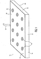
- Multi-point touch pad 10 is preferably unitarily formed and includes a base 20 having a top surface 38 that defines a plane.
- a wall 14 extends generally perpendicular to and away from the plane of top surface 38 at an edge of base 20.
- Base 20 combined with at least one wall 14 serves to form a touch pad enclosure 12.
- a support layer 26 having a top surface 32 and a bottom surface 28 may be approximately the same size and shape as the touch pad enclosure 12.
- Support layer 26 which can be formed of a soft foam-like material having shock absorbency properties, is disposed within touch pad enclosure 12.
- the support layer bottom surface 28 is seated adjacent and parallel to top surface 38.
- a plurality of sensors, preferably strain gauges 16, are placed adjacent to the support layer top surface 32, preferably in a matrix configuration.
- strain gauges 16 can offer more precise response properties and can be more cost effective as compared to the other sensors known by those skilled in the art. Strain gauges 16 are the preferred sensors for use in the present invention.
- a touch layer 24 is disposed on strain gauges 16 and is adhesively bonded thereto with strain gauges 16 forming a matrix configuration to effectuate an acceptable degree of coverage and responsiveness for multi-point touch pad 10.
- strain gauges 16 will sense a deformity of the strain gauge 16 and touch layer 24 combination which will cause a proportional change in the strain gauge 16 resistance. With a voltage placed on the strain gauge 16, the deformation and hence, the change in resistance, will result in a change in current flowing through (or voltage across) the strain gauge 16; a change in current (or voltage) which is measurable.
- touch layer 24 having a touch layer top surface 18 and a touch layer bottom surface 34, touch layer 24 being advantageously formed of an elastic material such as spring steel or bronze and touch layer 24 further having properties to insulate strain gauges 16 from moisture and dust infiltration while also being sensitive and precise to the touch.
- support layer 26 Disposed adjacent to strain gauges 16 is support layer 26 which keeps strain gauges 16 flat when no pressure is exerted on them, thereby preventing erroneous readings from multi-point touch pad 10.
- strain gauges 16 each contain a pair of sensor wires 36. Sensor wires 36 are further connected to a digital signal processor (DSP) 50. The sensor wires 36 are encapsulated within signal cable 22, signal cable 22 being connected to touch pad enclosure 12 and to DSP 50. The DSP 50, processes signals received from strain gauges 16 through sensor wires 36 with the assistance of an algorithm (e.g. software programmed) contained within DSP 50.
- DSP digital signal processor
- DSP 50 is constructed to implement the algorithm represented by the flowchart depicted in Figure 4.
- the software that controls the algorithm of DSP 50 may be programmed by different programmers in various forms or programming languages. However, the functionality should remain consistent with the mathematical formulas for the multi-point touch pad 10 to function according to its design.
- a flow chart 112 illustrated in Figure 4 depicts the operation and performance of multi-point touch pad 10 having the DSP 50 which contains a software programmed algorithm therein.
- Flow Chart 112 contains a touch module 100 which illustrates a user touching the touch pad with a single position and pressure or with simultaneous positions and pressures. With reference to sensing module 102 the touch by the user causes a change in the resistances of one or more of strain gauges 16. The resistance changes are registered on strain gauges 16 which are then transmitted through sensor wires 36 to DSP 50. DSP 50 then samples the signal as illustrated in DSP sampling module 104.
- N the number of strain gauges 16
- )z_M, i 1, ..., N; where w(
- the software algorithm of DSP 50 further calculates that: w(
- the software algorithm further calculates that
- sqrt((x_j- a_i)* (x_j- a_i) - (y_j-b_i)* (y_j - b_i)) as being the distance between the touch point ofj and the sensor i.
- the notation "sqrt" is representative of square root.
- the equation calculates that the pressure measured at strain gauge 16, and "i" is a summation of the pressure components caused by multiple touch points.
- Each pressure component is a function of the pressure of the corresponding touch point, the distance between the touch point and the location of the sensor. The farther the distance between a touch point and an individual strain gauge 16, the less effect the touch point has on the strain gauge 16.
- the results of the calculations performed in DSP calculation module 106 are then outputted via a DSP output module 108 to an application as illustrated in an application module 110.
- a multi-point touch pad 10 contains strain gauges 16 which are connected to DSP 50 through sensor wires 36.
- DSP 50 is further connected to application board 60 which would control the applications utilizing the output signals from DSP 50.
- Applications controlled by application board 60 may include computer equipment, videogame controllers, music devices, alternative keyboards and the like.
Landscapes
- Engineering & Computer Science (AREA)
- General Engineering & Computer Science (AREA)
- Theoretical Computer Science (AREA)
- Human Computer Interaction (AREA)
- Physics & Mathematics (AREA)
- General Physics & Mathematics (AREA)
- Position Input By Displaying (AREA)
- Force Measurement Appropriate To Specific Purposes (AREA)
- Mechanical Pencils And Projecting And Retracting Systems Therefor, And Multi-System Writing Instruments (AREA)
- Switches Operated By Changes In Physical Conditions (AREA)
Claims (14)
- Touchpad für Simultaneingaben, das Folgendes umfasst:- eine Berührungsschicht (24) mit einer oberen Fläche (18) und einer unteren Fläche (34) und mit einer Anzahl druckempfindlichen Vorrichtungen (16), die mit der unteren Fläche der Berührungsschicht (24) gekoppelt sind, so dass auf die obere Fläche ausgeübter Berührungsdruck auf die druckempfindlichen Vorrichtungen (16) in der Nähe der Stelle des Berührungsdrucks Druck ausüben wird,wobei jede druckempfindliche Vorrichtung (16), die mit einem Prozessor (50) gekoppelt ist, derart konstruiert ist, dass dieser die Position wenigstens zweier Berührungsstellen auf der oberen Fläche (18) berechnet, die gleichzeitig berührt worden sind, und zwar auf Basis von Druckempfindungswerten aus den druckempfindlichen Vorrichtungen (16) dadurch gekennzeichnet, dass der Prozessor dazu vorgesehen ist, eine Kombination der Auslesewerte zu benutzen, wobei je größer der Abstand zwischen einer bestimmten Stelle der Berührungsstellen und einer bestimmten Vorrichtung der vielen druckempfindlichen Vorrichtungen ist, umso kleiner ist der Effekt, den die Berührungsstelle auf den Druck hat, der von der einzelnen druckempfindlichen Vorrichtung erfahren wird.
- Touchpad nach Anspruch 1, wobei der Prozessor (50) auch konstruiert ist um den an jeder berührten Stelle ausgeübten Druck zu berechnen.
- Touchpad nach Anspruch 1, wobei jede der druckempfindlichen Vorrichtungen (16) einen Sensor aufweist, selektiert aus der Gruppe, bestehend aus: Kraftfühlwiderständen, piezoelektrischen Sensoren und kapazitiven Berührungssensoren.
- Touchpad nach Anspruch 1, wobei die druckempfindliche Vorrichtung (16) einen Dehnungsmessstreifen aufweist.
- Touchpad nach Anspruch 1, wobei die Drucksensoren (16) in einer Matrix vorgesehen sind.
- Touchpad nach Anspruch 1, wobei der Prozessor (50) derart konstruiert ist, dass er die nachfolgenden Algorithmen durchführt:- das Abtasten der Drucksensorauslesewerte aus den vielen druckempfindlichen Vorrichtungen (16),- das Berechnen von Stellen einzelner oder mehrfacher Berührungen auf dem Touchpad (10) ;- das Berechnen eine Betrags an Druck, ausgeübt bei jeder Berührung des Touchpads (10)- das Ausliefern von Berechnungsdaten.
- Touchpad nach Anspruch 6, wobei der Prozessor (50) derart konstruiert ist, dass er den Algorithmus durchführt, der die bekannten Stellen der druckempfindlichen Vorrichtungen (16) auf dem Touchpad für Simultaneingaben enthält; wobei die Stellen mit der nachfolgenden Formel identifiziert werden: (a_i, b_i), i = 1, 2, ..., N, wobei N die Anzahl druckempfindlicher Vorrichtungen (16) ist, und wobei die gemessenen Drücke der druckempfindlichen Vorrichtungen (16) p_i, i = 1, 2, ..., N sind; wobei die Position der Berührungsstellen auf dem Touchpad (10) mit der nachfolgenden Formal identifiziert wird: (x_j, y_j), j = 1, 2, ..., M, wobei M eine bekannte Anzahl Berührungsstellen ist (weniger als N), wobei aber x_j und y_j unbekannt sind und durch die Berechnungen der Formel ermittelt werden; wobei die Drücke der Berührungsstellen mit der nachfolgenden Formel identifiziert werden: z_j, j = 1, 2, ..., M, die auch unter Anwendung des Algorithmus berechnet werden sollen; wobei der Algorithmus die Abtastdaten von einem DSP Abtastmodul (104) zu einem Prozessorrechenmodul (106) überträgt, wobei der Algorithmus die Position und den Druck der Berührungsstellen berechnet, und zwar unter Anwendung der nachfolgenden mathematischen Formel: : p_i = w(|(x_1, y_1) - (a_i, b_i)| ) z_1 + w( |(x_2, y_2) - (a_i, b_1)|)z_2 + ... + w(|(x_M, y_M) - (a_i, b_1)|)z_M, i = 1, ..., N; wobei w(|(x_i, y_j) - (a_i, b_i)|) ein Gewichtungsfaktor ist, der den Effekt des Drucks von z_j auf p_i reflektiert; wobei der Algorithmus berechnet, dass: w(|(x_i, y_j) - (a_i, b_i)|) eine Funktion des Abstandes zwischen der Berührungsstelle (x_j, y_j) und der Sensorstelle (a_i, b_i) ist; wobei der Algorithmus berechnet, dass |(x_j, y_j) - (a_i, b_i)| = sqrt((x_j - a_i)* (x_j - a_i) - (y_j - b_i)* (y_j - b_i)) ist, und zwar der Abstand zwischen der Berührungsstelle von j und dem Sensor i, unter Anwendung der Notierung "sqrt" als Darstellung der Quadratwurzel.
- Verfahren zur Steuerung einer Applikation mit einem Touchpad (10) mit einer Berührungsfläche (24) mit einer unteren und einer oberen Fläche und einer Anzahl druckempfindlicher Vorrichtungen (16), vorgesehen unter der Berührungsfläche (24) und mit dem Boden der Berührungsfläche gekoppelt; wobei das Verfahren die nachfolgenden Verfahrensschritte umfasst:- das Fühlen einer gleichzeitigen Berührung der oberen Berührungsfläche von wenigstens zwei Berührungsstellen;- das Senden eines Signals zu einem Prozessor (50) entsprechend einem Druck bei jeder Vorrichtung (16);dadurch gekennzeichnet, dass ein Algorithmus durchgeführt wird zum ermitteln von Positionen der wenigstens zwei Berührungsstellen auf Basis von Drucksensorwerten von den druckempfindlichen Vorrichtungen (16), und zwar unter Verwendung eines gewichteten Kombination der Auslesewerte, wobei je größer ein Abstand zwischen einer spezifischen Stelle der Berührungsstellen und einer einzelnen Vorrichtung der vielen druckempfindlichen Vorrichtungen ist, umso kleiner ist der Effekt von Druck an der Berührungsstelle, der von der einzelnen druckempfindlichen Vorrichtung gespürt wird.
- Verfahren nach Anspruch 8, das weiterhin den nachfolgenden Verfahrensschritt hat:- das Berechnen des an jeder Berührungsstelle ausgeübten Drucks.
- Verfahren nach Anspruch 8, wobei jede der druckempfindlichen Vorrichtungen (16) aus der Gruppe selektiert wird, die aus kraftempfindlichen Widerständen, piezoelektrischen Sensoren und kapazitiven Berührungssensoren besteht.
- Verfahren nach Anspruch 8, wobei die druckempfindlichen Vorrichtungen (16) Dehnungsmessstreifen enthalten.
- Verfahren nach Anspruch 8, wobei die Drucksensoren (16) in einer Matrixkonfiguration vorgesehen sind.
- Verfahren nach Anspruch 8, wobei die Durchführung des Algorithmus die nachfolgenden Verfahrensschritte umfasst:- das Abtasten der Auslesewerte,- das Berechnen von Stellen einer einzigen oder mehrfachen Berührung des Touchpads (10);- das Berechnen eines Betrags an Druck, ausgeübt bei jeder Berührung des Touchpads (10);- das Ausliefern von Rechendaten von dem Algorithmus zur Steuerung der Applikation.
- Verfahren nach Anspruch 8, das weiterhin die nachfolgenden Verfahrensschritte umfasst:- das Identifizieren der Positionen der druckempfindlichen Vorrichtungen mit der Formel (a_i, b_i), i = 1, 2, ..., N, wobei N die Anzahl druckempfindlicher Vorrichtungen (16) ist, und wobei die gemessenen Drücke der druckempfindlichen Vorrichtungen (16) p_i, i = 1, 2, ... , N sind;- das Programmieren der Position der Berührungsstellen auf dem Touchpad (10) mit der nachfolgenden Formal identifiziert wird: (x_j, y_j), j = 1, 2, ..., M, wobei M eine bekannte Anzahl Berührungsstellen ist (weniger als N), wobei aber x_j und y_j unbekannt sind und durch die Berechnungen des Algorithmus ermittelt werden;- das Quantifizieren der Drücke der Berührungsstellen mit der Formel: z_j, j = 1, 2, ..., M, und zwar unter Anwendung des Algorithmus;- das Übertragen von Abtastdaten von einem Abtastmodul (104) zu einem Rechenmodul (106) ;- das Berechnen der Position und des Drucks der Berührungsstellen, und zwar unter Anwendung der nachfolgenden mathematischen Formel: : p_i = w(|(x_1, y_1) - (a_i, b_i)| ) z_1 + w(|(x_2, y_2) - (a_i, b_1)|)z_2 + ... + w(|(x_M, y_M) - (a_i, b_i)|)z_M, i = 1, ..., N; wobei w(|(x_i, y_j) - (a_i, b_i)|) ein Gewichtungsfaktor ist, der den Effekt des Drucks von z_j auf p_i reflektiert;- das Berechnen, dass: w(|(x_i, y_j) - (a_i, b_i)|) eine Funktion des Abstandes zwischen der Berührungsstelle (x_j, y_j) und der Sensorstelle (a_i, b_i) ist, und zwar unter Anwendung des Algorithmus;- das Berechnen, dass |(x_j, y_j) - (a_i, b_i)| = sqrt((x_j - a_i)* (x_j - a_i) - (y_j - b_i)* (y_j - b_i)) ist, und zwar der Abstand zwischen der Berührungsstelle von j und dem Sensor i, unter Anwendung der Notierung "sqrt" als Darstellung der Quadratwurzel.
Applications Claiming Priority (3)
| Application Number | Priority Date | Filing Date | Title |
|---|---|---|---|
| US10/008,216 US6995752B2 (en) | 2001-11-08 | 2001-11-08 | Multi-point touch pad |
| US8216 | 2001-11-08 | ||
| PCT/IB2002/004644 WO2003041006A1 (en) | 2001-11-08 | 2002-11-05 | Multi-point touch pad |
Publications (2)
| Publication Number | Publication Date |
|---|---|
| EP1446764A1 EP1446764A1 (de) | 2004-08-18 |
| EP1446764B1 true EP1446764B1 (de) | 2007-10-17 |
Family
ID=21730397
Family Applications (1)
| Application Number | Title | Priority Date | Filing Date |
|---|---|---|---|
| EP02779824A Expired - Lifetime EP1446764B1 (de) | 2001-11-08 | 2002-11-05 | Touchpad für simultaneingaben |
Country Status (9)
| Country | Link |
|---|---|
| US (1) | US6995752B2 (de) |
| EP (1) | EP1446764B1 (de) |
| JP (1) | JP4194944B2 (de) |
| KR (1) | KR100971455B1 (de) |
| CN (1) | CN100353305C (de) |
| AT (1) | ATE376223T1 (de) |
| DE (1) | DE60223072T2 (de) |
| ES (1) | ES2295421T3 (de) |
| WO (1) | WO2003041006A1 (de) |
Families Citing this family (186)
| Publication number | Priority date | Publication date | Assignee | Title |
|---|---|---|---|---|
| US7663607B2 (en) | 2004-05-06 | 2010-02-16 | Apple Inc. | Multipoint touchscreen |
| US7800592B2 (en) * | 2005-03-04 | 2010-09-21 | Apple Inc. | Hand held electronic device with multiple touch sensing devices |
| US7808479B1 (en) | 2003-09-02 | 2010-10-05 | Apple Inc. | Ambidextrous mouse |
| US7614008B2 (en) * | 2004-07-30 | 2009-11-03 | Apple Inc. | Operation of a computer with touch screen interface |
| JP4768143B2 (ja) * | 2001-03-26 | 2011-09-07 | 株式会社リコー | 情報入出力装置、情報入出力制御方法およびプログラム |
| JP3708508B2 (ja) * | 2001-08-23 | 2005-10-19 | 株式会社アイム | 指先触覚入力装置及びそれを用いた携帯情報端末 |
| US7656393B2 (en) | 2005-03-04 | 2010-02-02 | Apple Inc. | Electronic device having display and surrounding touch sensitive bezel for user interface and control |
| US11275405B2 (en) * | 2005-03-04 | 2022-03-15 | Apple Inc. | Multi-functional hand-held device |
| US7618323B2 (en) * | 2003-02-26 | 2009-11-17 | Wms Gaming Inc. | Gaming machine system having a gesture-sensing mechanism |
| AU2003260804A1 (en) * | 2003-08-29 | 2005-03-16 | Nokia Corporation | Method and device for recognizing a dual point user input on a touch based user input device |
| US9024884B2 (en) | 2003-09-02 | 2015-05-05 | Apple Inc. | Touch-sensitive electronic apparatus for media applications, and methods therefor |
| US7180506B2 (en) * | 2004-02-12 | 2007-02-20 | Sentelic Corporation | Method for identifying a movement of single tap on a touch device |
| FR2866726B1 (fr) * | 2004-02-23 | 2006-05-26 | Jazzmutant | Controleur par manipulation d'objets virtuels sur un ecran tactile multi-contact |
| US7184031B2 (en) * | 2004-07-06 | 2007-02-27 | Sentelic Corporation | Method and controller for identifying a drag gesture |
| JP4405335B2 (ja) * | 2004-07-27 | 2010-01-27 | 株式会社ワコム | 位置検出装置、及び、入力システム |
| JP4903371B2 (ja) * | 2004-07-29 | 2012-03-28 | 任天堂株式会社 | タッチパネルを用いたゲーム装置およびゲームプログラム |
| CN100508533C (zh) * | 2004-08-12 | 2009-07-01 | 郦东 | 一种用户界面装置及其便携式终端 |
| US7661309B2 (en) * | 2004-10-04 | 2010-02-16 | Industrial Research Limited | Angle and force measurement instrument |
| US20060176279A1 (en) * | 2005-02-08 | 2006-08-10 | Research In Motion | Handheld electronic device having keyboard that provides two-dimensional navigation, and associated method |
| EP1688830A1 (de) * | 2005-02-08 | 2006-08-09 | Research In Motion Limited | Tragbares elektronisches Gerät mit Tastatur, die eine zweidimensionale Navigation ermöglicht, und dazugehöriges Verfahren |
| CN101133385B (zh) * | 2005-03-04 | 2014-05-07 | 苹果公司 | 手持电子设备、手持设备及其操作方法 |
| AU2013204606A1 (en) * | 2005-03-04 | 2013-05-09 | Apple Inc. | Multi-functional hand-held device |
| KR101984833B1 (ko) * | 2005-03-04 | 2019-06-03 | 애플 인크. | 다기능 휴대용 장치 |
| US20070024591A1 (en) * | 2005-07-27 | 2007-02-01 | Tyco Electronics Corporation | Retrofit touch sensor controls |
| KR100784956B1 (ko) | 2005-12-14 | 2007-12-11 | 한국표준과학연구원 | 촉각센서를 이용한 데이터 입력 방법 |
| KR101230309B1 (ko) * | 2006-01-27 | 2013-02-06 | 삼성디스플레이 주식회사 | 표시 장치 및 감지 신호 처리 장치 |
| US7656392B2 (en) * | 2006-03-24 | 2010-02-02 | Synaptics Incorporated | Touch sensor effective area enhancement |
| US7538760B2 (en) * | 2006-03-30 | 2009-05-26 | Apple Inc. | Force imaging input device and system |
| US8062115B2 (en) * | 2006-04-27 | 2011-11-22 | Wms Gaming Inc. | Wagering game with multi-point gesture sensing device |
| US9063647B2 (en) | 2006-05-12 | 2015-06-23 | Microsoft Technology Licensing, Llc | Multi-touch uses, gestures, and implementation |
| CN104965621B (zh) | 2006-06-09 | 2018-06-12 | 苹果公司 | 触摸屏液晶显示器及其操作方法 |
| KR101295943B1 (ko) | 2006-06-09 | 2013-08-13 | 애플 인크. | 터치 스크린 액정 디스플레이 |
| US8552989B2 (en) | 2006-06-09 | 2013-10-08 | Apple Inc. | Integrated display and touch screen |
| US9086737B2 (en) * | 2006-06-15 | 2015-07-21 | Apple Inc. | Dynamically controlled keyboard |
| US7959521B2 (en) | 2006-06-21 | 2011-06-14 | Nusbaum Mark E | Electronically controlled golf swing analyzing/training mat system with ball striking-related feedback |
| US20070298895A1 (en) * | 2006-06-21 | 2007-12-27 | Nusbaum Mark E | Golf swing analyzing/training mat system with ball striking-related feedback |
| KR100791102B1 (ko) | 2006-08-16 | 2008-01-02 | (주)휴엔텍 | 터치패드형 리모콘 |
| KR100866485B1 (ko) * | 2006-08-22 | 2008-11-03 | 삼성전자주식회사 | 다접점 위치 변화 감지 장치, 방법, 및 이를 이용한 모바일기기 |
| DE202006020563U1 (de) * | 2006-09-02 | 2009-02-19 | Imc Messsysteme Gmbh | Lötstützpunkte-Flächenelement |
| CN101512468A (zh) * | 2006-09-09 | 2009-08-19 | F-原点股份有限公司 | 集成压力敏感透镜组件 |
| TW200822019A (en) * | 2006-11-08 | 2008-05-16 | Amtran Technology Co Ltd | Touch screen on-screen display (OSD) control device and control method thereof and liquid crystal displays |
| US8269746B2 (en) | 2006-11-27 | 2012-09-18 | Microsoft Corporation | Communication with a touch screen |
| US8094129B2 (en) * | 2006-11-27 | 2012-01-10 | Microsoft Corporation | Touch sensing using shadow and reflective modes |
| US7924272B2 (en) * | 2006-11-27 | 2011-04-12 | Microsoft Corporation | Infrared sensor integrated in a touch panel |
| KR20080056559A (ko) * | 2006-12-18 | 2008-06-23 | 엘지전자 주식회사 | 터치스크린 장치 및 이를 구비한 디지털 기기 그리고 이의명령 입력방법 |
| US8493330B2 (en) | 2007-01-03 | 2013-07-23 | Apple Inc. | Individual channel phase delay scheme |
| US9710095B2 (en) * | 2007-01-05 | 2017-07-18 | Apple Inc. | Touch screen stack-ups |
| KR101338992B1 (ko) * | 2007-04-24 | 2013-12-09 | 엘지디스플레이 주식회사 | 액정표시장치의 터치패드 장치 |
| US8355009B2 (en) * | 2007-04-25 | 2013-01-15 | Mcdermid William J | Method and apparatus for determining coordinates of simultaneous touches on a touch sensor pad |
| US20080297174A1 (en) * | 2007-05-31 | 2008-12-04 | Sarangan Narasimhan | Capacitive sensing devices |
| EP2017703A1 (de) | 2007-07-09 | 2009-01-21 | Sensitive Object | Berührungssteuerungssystem und Verfahren zur Lokalisierung einer Erregung |
| KR101395780B1 (ko) * | 2007-07-27 | 2014-05-16 | 삼성전자주식회사 | 촉각 감지를 위한 압력 센서 어레이 장치 및 방법 |
| US8026906B2 (en) * | 2007-09-07 | 2011-09-27 | F-Origin, Inc. | Integrated force sensitive lens and software |
| CN101145089B (zh) * | 2007-10-31 | 2010-05-19 | 广东威创视讯科技股份有限公司 | 触摸屏装置与计算机通信的方法及装置 |
| CN101458601B (zh) * | 2007-12-14 | 2012-03-14 | 清华大学 | 触摸屏及显示装置 |
| US8067701B2 (en) * | 2008-01-07 | 2011-11-29 | Apple Inc. | I/O connectors with extendable faraday cage |
| EP2085866B1 (de) * | 2008-01-31 | 2010-06-09 | Research In Motion Limited | Elektronische Vorrichtung und Steuerverfahren dafür |
| KR100933710B1 (ko) * | 2008-02-12 | 2009-12-24 | 한국표준과학연구원 | 촉각센서를 장착한 디스플레이 일체형 플렉시블 터치스크린 및 이의 인식 알고리즘 구현 방법 |
| US20090213083A1 (en) * | 2008-02-26 | 2009-08-27 | Apple Inc. | Simulation of multi-point gestures with a single pointing device |
| EP4071785A1 (de) * | 2008-02-28 | 2022-10-12 | 3M Innovative Properties Company | Berührungsbildschirmsensor |
| US8717305B2 (en) * | 2008-03-04 | 2014-05-06 | Apple Inc. | Touch event model for web pages |
| US8270148B2 (en) * | 2008-03-14 | 2012-09-18 | David Griffith | Suspension for a pressure sensitive touch display or panel |
| CN101539825B (zh) * | 2008-03-18 | 2012-05-23 | 禾瑞亚科技股份有限公司 | 投影电容式触控面板的判定多触点位置的装置及其方法 |
| KR20090112118A (ko) * | 2008-04-23 | 2009-10-28 | 엘지이노텍 주식회사 | 표시장치 |
| CN101271372B (zh) * | 2008-05-06 | 2010-10-13 | 党韧 | 一种多点触摸屏 |
| CN101576770B (zh) * | 2008-05-07 | 2011-09-21 | 联想(北京)有限公司 | 多触点交互系统及方法 |
| US8110744B2 (en) * | 2008-08-19 | 2012-02-07 | Apple Inc. | Flexible shielded cable |
| US9477342B2 (en) * | 2008-08-26 | 2016-10-25 | Google Technology Holdings LLC | Multi-touch force sensing touch-screen devices and methods |
| JP2010102474A (ja) * | 2008-10-23 | 2010-05-06 | Sony Ericsson Mobile Communications Ab | 情報表示装置、携帯情報端末、表示制御方法及び表示制御プログラム |
| CN101727222B (zh) * | 2008-10-27 | 2012-04-18 | 华晶科技股份有限公司 | 压力感测模块及具压力感测模块的触控式屏幕 |
| KR101016221B1 (ko) * | 2008-11-14 | 2011-02-25 | 한국표준과학연구원 | 힘 센서를 구비한 입력모듈에 터치 입력을 처리하기 위한 알고리즘 구현방법 |
| KR101637879B1 (ko) * | 2009-02-06 | 2016-07-08 | 엘지전자 주식회사 | 휴대 단말기 및 그 동작방법 |
| CN102365608B (zh) * | 2009-03-31 | 2016-06-22 | 日本写真印刷株式会社 | 信息输入装置及在信息输入装置中使用的压力检测单元 |
| CN104035629B (zh) * | 2009-04-22 | 2017-04-12 | 三菱电机株式会社 | 位置输入装置 |
| KR101576292B1 (ko) * | 2009-05-21 | 2015-12-09 | 엘지전자 주식회사 | 이동 통신 단말기에서의 메뉴 실행 방법 및 이를 적용한 이동 통신 단말기 |
| KR101121127B1 (ko) * | 2009-05-26 | 2012-03-19 | 김기택 | 터치 스크린 표시장치 |
| KR101082289B1 (ko) * | 2009-05-28 | 2011-11-09 | 강동섭 | 터치신호발생기 |
| US8654524B2 (en) | 2009-08-17 | 2014-02-18 | Apple Inc. | Housing as an I/O device |
| KR20110027117A (ko) * | 2009-09-09 | 2011-03-16 | 삼성전자주식회사 | 터치 패널을 구비한 전자 장치와 표시 방법 |
| US8487759B2 (en) * | 2009-09-30 | 2013-07-16 | Apple Inc. | Self adapting haptic device |
| EP2320308B1 (de) * | 2009-10-13 | 2017-05-10 | BlackBerry Limited | Tragbare elektronische Vorrichtung mit berührungsempfindlicher Anzeige und Verfahren zu deren Steuerung |
| US9383847B2 (en) * | 2009-10-13 | 2016-07-05 | Blackberry Limited | Portable electronic device including touch-sensitive display and method of controlling same |
| CN102043501B (zh) | 2009-10-26 | 2016-03-23 | 宸鸿光电科技股份有限公司 | 力感测器的集成排线模块及压感式触控荧幕 |
| US20110102331A1 (en) * | 2009-10-29 | 2011-05-05 | Qrg Limited | Redundant touchscreen electrodes |
| JP5371712B2 (ja) * | 2009-11-26 | 2013-12-18 | 京セラ株式会社 | キー入力装置および携帯端末 |
| US8570297B2 (en) * | 2009-12-14 | 2013-10-29 | Synaptics Incorporated | System and method for measuring individual force in multi-object sensing |
| US9164605B1 (en) * | 2010-02-03 | 2015-10-20 | Cypress Semiconductor Corporation | Force sensor baseline calibration |
| CN101893953B (zh) * | 2010-03-11 | 2012-12-26 | 宇龙计算机通信科技(深圳)有限公司 | 一种触摸屏的触控信息的处理方法和系统 |
| US9007190B2 (en) | 2010-03-31 | 2015-04-14 | Tk Holdings Inc. | Steering wheel sensors |
| US8587422B2 (en) | 2010-03-31 | 2013-11-19 | Tk Holdings, Inc. | Occupant sensing system |
| JP5759230B2 (ja) | 2010-04-02 | 2015-08-05 | ティーケー ホールディングス,インコーポレーテッド | 手センサを有するステアリング・ホイール |
| CN101859211B (zh) * | 2010-05-21 | 2013-05-29 | 汉王科技股份有限公司 | 手指触控定位装置及方法 |
| US9158401B2 (en) | 2010-07-01 | 2015-10-13 | Flatfrog Laboratories Ab | Data processing in relation to a multi-touch sensing apparatus |
| US8884910B2 (en) | 2010-08-30 | 2014-11-11 | Microsoft Corporation | Resistive matrix with optimized input scanning |
| US10013058B2 (en) | 2010-09-21 | 2018-07-03 | Apple Inc. | Touch-based user interface with haptic feedback |
| IT1402569B1 (it) | 2010-11-12 | 2013-09-13 | Pirelli | Metodo per controllare la gestione di strutture anulari di ancoraggio in un processo ed un impianto per confezionare pneumatici per ruote di veicoli |
| US10120446B2 (en) | 2010-11-19 | 2018-11-06 | Apple Inc. | Haptic input device |
| US8804056B2 (en) | 2010-12-22 | 2014-08-12 | Apple Inc. | Integrated touch screens |
| JP2012152521A (ja) * | 2011-01-28 | 2012-08-16 | Japan Science & Technology Agency | マッサージ機器の操作装置 |
| CN102109942B (zh) * | 2011-02-18 | 2012-08-29 | 福建鑫诺通讯技术有限公司 | 一种基于电阻式屏幕实现两点触摸的方法 |
| US8959459B2 (en) | 2011-06-15 | 2015-02-17 | Wms Gaming Inc. | Gesture sensing enhancement system for a wagering game |
| EP2535840A1 (de) * | 2011-06-16 | 2012-12-19 | Printechnologics GmbH | Mittel zur unidirektionalen oder bidirektionalen Datenübertragung |
| TW201329815A (zh) * | 2011-10-14 | 2013-07-16 | Nextinput Inc | 力敏感介面裝置及使用其之方法 |
| US8933896B2 (en) * | 2011-10-25 | 2015-01-13 | Microsoft Corporation | Pressure-based interaction for indirect touch input devices |
| CN102425842B (zh) * | 2011-12-07 | 2014-06-04 | 广东美的制冷设备有限公司 | 支持双点调节空调设定信息的空调装置及其控制方法 |
| US9246486B2 (en) | 2011-12-16 | 2016-01-26 | Apple Inc. | Electronic device with noise-cancelling force sensor |
| WO2013154720A1 (en) | 2012-04-13 | 2013-10-17 | Tk Holdings Inc. | Pressure sensor including a pressure sensitive material for use with control systems and methods of using the same |
| US9086732B2 (en) | 2012-05-03 | 2015-07-21 | Wms Gaming Inc. | Gesture fusion |
| US9493342B2 (en) | 2012-06-21 | 2016-11-15 | Nextinput, Inc. | Wafer level MEMS force dies |
| WO2014008377A1 (en) | 2012-07-05 | 2014-01-09 | Ian Campbell | Microelectromechanical load sensor and methods of manufacturing the same |
| KR101363876B1 (ko) * | 2012-07-06 | 2014-02-18 | (주)멜파스 | 멀티 터치 입력 처리 방법 및 장치 |
| US8893565B2 (en) * | 2012-07-13 | 2014-11-25 | Nokia Corporation | Apparatus for sensing |
| WO2014033872A1 (ja) * | 2012-08-30 | 2014-03-06 | 富士通株式会社 | 表示装置,プログラム |
| WO2014043664A1 (en) | 2012-09-17 | 2014-03-20 | Tk Holdings Inc. | Single layer force sensor |
| US9178509B2 (en) | 2012-09-28 | 2015-11-03 | Apple Inc. | Ultra low travel keyboard |
| JP5898779B2 (ja) * | 2012-10-11 | 2016-04-06 | アルプス電気株式会社 | 入力装置及び前記入力装置を用いた複数点の荷重検出方法 |
| US10817096B2 (en) | 2014-02-06 | 2020-10-27 | Apple Inc. | Force sensor incorporated into display |
| DE112013005988B4 (de) | 2012-12-14 | 2023-09-21 | Apple Inc. | Krafterfassung durch Kapazitätsänderungen |
| KR20140084879A (ko) | 2012-12-27 | 2014-07-07 | 삼성전기주식회사 | 터치 패널과 비어 홀 및 비어 전극 제조 방법 |
| KR102058699B1 (ko) * | 2013-01-24 | 2019-12-26 | 삼성디스플레이 주식회사 | 터치 및 휨 감지 기능을 가지는 플렉서블 표시장치 |
| KR20150113169A (ko) | 2013-02-08 | 2015-10-07 | 애플 인크. | 용량성 감지에 기초한 힘 결정 |
| US9229592B2 (en) | 2013-03-14 | 2016-01-05 | Synaptics Incorporated | Shear force detection using capacitive sensors |
| WO2014143066A1 (en) | 2013-03-15 | 2014-09-18 | Rinand Solutions Llc | Touch force deflection sensor |
| US9671889B1 (en) | 2013-07-25 | 2017-06-06 | Apple Inc. | Input member with capacitive sensor |
| WO2015020663A1 (en) | 2013-08-08 | 2015-02-12 | Honessa Development Laboratories Llc | Sculpted waveforms with no or reduced unforced response |
| CN104423826B (zh) * | 2013-09-03 | 2018-07-31 | 上海炬力集成电路设计有限公司 | 一种使用鼠标中键和滚轮实现缩放的方法及装置 |
| US9779592B1 (en) | 2013-09-26 | 2017-10-03 | Apple Inc. | Geared haptic feedback element |
| WO2015047343A1 (en) | 2013-09-27 | 2015-04-02 | Honessa Development Laboratories Llc | Polarized magnetic actuators for haptic response |
| CN105579928A (zh) | 2013-09-27 | 2016-05-11 | 苹果公司 | 具有触觉致动器的带体 |
| WO2015047364A1 (en) | 2013-09-29 | 2015-04-02 | Pearl Capital Developments Llc | Devices and methods for creating haptic effects |
| US10236760B2 (en) | 2013-09-30 | 2019-03-19 | Apple Inc. | Magnetic actuators for haptic response |
| US9317118B2 (en) | 2013-10-22 | 2016-04-19 | Apple Inc. | Touch surface for simulating materials |
| US10120506B2 (en) | 2013-11-12 | 2018-11-06 | Microsoft Technology Licensing, Llc | Multi-touch capacitive sensing surface |
| US10276001B2 (en) | 2013-12-10 | 2019-04-30 | Apple Inc. | Band attachment mechanism with haptic response |
| CN105934661B (zh) | 2014-01-13 | 2019-11-05 | 触控解决方案股份有限公司 | 微型强化圆片级mems力传感器 |
| US9501912B1 (en) | 2014-01-27 | 2016-11-22 | Apple Inc. | Haptic feedback device with a rotating mass of variable eccentricity |
| CN106068490B (zh) | 2014-02-12 | 2019-02-22 | 苹果公司 | 采用片式传感器和电容阵列的力确定 |
| DE112014006608B4 (de) | 2014-04-21 | 2024-01-25 | Apple Inc. | Verfahren, Systeme und elektronische Vorrichtungen zum Bestimmen der Kräfteaufteilung für Multi-Touch-Eingabevorrichtungen elektronischer Vorrichtungen |
| WO2015163843A1 (en) | 2014-04-21 | 2015-10-29 | Rinand Solutions Llc | Mitigating noise in capacitive sensor |
| DE102015209639A1 (de) | 2014-06-03 | 2015-12-03 | Apple Inc. | Linearer Aktuator |
| US9411458B2 (en) * | 2014-06-30 | 2016-08-09 | Synaptics Incorporated | System and method for determining input object information from proximity and force measurements |
| CN104133708A (zh) * | 2014-08-05 | 2014-11-05 | 广州市思码触屏科技有限公司 | 一种电阻式多点触摸计算机操作系统 |
| US9830782B2 (en) | 2014-09-02 | 2017-11-28 | Apple Inc. | Haptic notifications |
| US10353467B2 (en) | 2015-03-06 | 2019-07-16 | Apple Inc. | Calibration of haptic devices |
| US10006937B2 (en) | 2015-03-06 | 2018-06-26 | Apple Inc. | Capacitive sensors for electronic devices and methods of forming the same |
| AU2016100399B4 (en) | 2015-04-17 | 2017-02-02 | Apple Inc. | Contracting and elongating materials for providing input and output for an electronic device |
| US10466119B2 (en) | 2015-06-10 | 2019-11-05 | Nextinput, Inc. | Ruggedized wafer level MEMS force sensor with a tolerance trench |
| US9715301B2 (en) | 2015-08-04 | 2017-07-25 | Apple Inc. | Proximity edge sensing |
| CN105117055B (zh) * | 2015-08-14 | 2018-09-28 | 宸鸿科技(厦门)有限公司 | 触压式三维信号输入装置及使用方法及多功能触控面板 |
| WO2017044618A1 (en) | 2015-09-08 | 2017-03-16 | Apple Inc. | Linear actuators for use in electronic devices |
| DE102016105846A1 (de) | 2015-11-04 | 2017-05-04 | Preh Gmbh | Eingabegerät mit redundanter Detektion |
| US20190095024A1 (en) * | 2016-02-04 | 2019-03-28 | Shenzhen New Degree Technology Co., Ltd. | Pressure sensing device and electronic apparatus having same |
| US10039080B2 (en) | 2016-03-04 | 2018-07-31 | Apple Inc. | Situationally-aware alerts |
| US10007343B2 (en) | 2016-03-31 | 2018-06-26 | Apple Inc. | Force sensor in an input device |
| US10268272B2 (en) | 2016-03-31 | 2019-04-23 | Apple Inc. | Dampening mechanical modes of a haptic actuator using a delay |
| US10209840B2 (en) | 2016-04-20 | 2019-02-19 | Lg Innotek Co., Ltd. | Touch window and touch device |
| CN108319361A (zh) * | 2017-01-17 | 2018-07-24 | 中兴通讯股份有限公司 | 一种反馈方法和装置 |
| CN116679845A (zh) | 2017-02-06 | 2023-09-01 | 平蛙实验室股份公司 | 触摸感测装置 |
| EP4701393A2 (de) | 2017-02-09 | 2026-02-25 | Nextinput, Inc. | Integrierte digitale kraftsensoren und zugehörige verfahren zur herstellung |
| WO2018148510A1 (en) | 2017-02-09 | 2018-08-16 | Nextinput, Inc. | Integrated piezoresistive and piezoelectric fusion force sensor |
| CN108571925B (zh) * | 2017-03-10 | 2020-10-20 | 上海敏传智能科技有限公司 | 一种柔性显示器形变感知系统 |
| US10622538B2 (en) | 2017-07-18 | 2020-04-14 | Apple Inc. | Techniques for providing a haptic output and sensing a haptic input using a piezoelectric body |
| EP3655740A4 (de) | 2017-07-19 | 2021-07-14 | Nextinput, Inc. | Spannungstransferstapelung in einem mems-kraftsensor |
| WO2019023309A1 (en) | 2017-07-25 | 2019-01-31 | Nextinput, Inc. | FORCE SENSOR AND INTEGRATED FINGERPRINTS |
| WO2019023552A1 (en) | 2017-07-27 | 2019-01-31 | Nextinput, Inc. | PIEZORESISTIVE AND PIEZOELECTRIC FORCE SENSOR ON WAFER AND METHODS OF MANUFACTURING THE SAME |
| CN107562271A (zh) * | 2017-08-30 | 2018-01-09 | 广东深越光电技术有限公司 | 一种能检测多点触摸的压力信号的触摸显示装置 |
| US11256371B2 (en) | 2017-09-01 | 2022-02-22 | Flatfrog Laboratories Ab | Optical component |
| KR101959426B1 (ko) * | 2017-09-06 | 2019-03-19 | 주식회사 하이딥 | 스트레인 게이지를 포함하는 터치 입력 장치 |
| WO2019079420A1 (en) | 2017-10-17 | 2019-04-25 | Nextinput, Inc. | SHIFT TEMPERATURE COEFFICIENT COMPENSATION FOR FORCE SENSOR AND STRAIN GAUGE |
| WO2019090057A1 (en) | 2017-11-02 | 2019-05-09 | Nextinput, Inc. | Sealed force sensor with etch stop layer |
| WO2019099821A1 (en) | 2017-11-16 | 2019-05-23 | Nextinput, Inc. | Force attenuator for force sensor |
| WO2019172826A1 (en) | 2018-03-05 | 2019-09-12 | Flatfrog Laboratories Ab | Improved touch-sensing apparatus |
| US10866683B2 (en) | 2018-08-27 | 2020-12-15 | Apple Inc. | Force or touch sensing on a mobile device using capacitive or pressure sensing |
| US10691211B2 (en) | 2018-09-28 | 2020-06-23 | Apple Inc. | Button providing force sensing and/or haptic output |
| US10599223B1 (en) | 2018-09-28 | 2020-03-24 | Apple Inc. | Button providing force sensing and/or haptic output |
| US12055969B2 (en) | 2018-10-20 | 2024-08-06 | Flatfrog Laboratories Ab | Frame for a touch-sensitive device and tool therefor |
| US10962427B2 (en) | 2019-01-10 | 2021-03-30 | Nextinput, Inc. | Slotted MEMS force sensor |
| US11380470B2 (en) | 2019-09-24 | 2022-07-05 | Apple Inc. | Methods to control force in reluctance actuators based on flux related parameters |
| CN114730228A (zh) | 2019-11-25 | 2022-07-08 | 平蛙实验室股份公司 | 一种触摸感应设备 |
| WO2021158164A1 (en) | 2020-02-08 | 2021-08-12 | Flatfrog Laboratories Ab | Touch apparatus with low latency interactions |
| KR102950284B1 (ko) | 2020-02-10 | 2026-04-09 | 플라트프로그 라보라토리즈 에이비 | 향상된 터치-감지 장치 |
| DE102020112982A1 (de) * | 2020-05-13 | 2021-11-18 | Voss Fluid Gmbh | Verbindungsstutzen für fluidführende Leitungssysteme |
| US11977683B2 (en) | 2021-03-12 | 2024-05-07 | Apple Inc. | Modular systems configured to provide localized haptic feedback using inertial actuators |
| US11774940B2 (en) | 2021-03-29 | 2023-10-03 | Rockwell Automation Technologies, Inc. | Redundant touchless inputs for automation system |
| US11809631B2 (en) | 2021-09-21 | 2023-11-07 | Apple Inc. | Reluctance haptic engine for an electronic device |
| CN116166146B (zh) * | 2023-01-07 | 2024-01-16 | 上海耀杉电子科技有限公司 | 液态压阻式触摸结构及使用该结构的柔性触摸屏 |
Family Cites Families (13)
| Publication number | Priority date | Publication date | Assignee | Title |
|---|---|---|---|---|
| US548820A (en) * | 1895-10-29 | Pneumatic tire and wheel-rim | ||
| US515915A (en) * | 1894-03-06 | Lttdwig luokhardt | ||
| US5241308A (en) * | 1990-02-22 | 1993-08-31 | Paragon Systems, Inc. | Force sensitive touch panel |
| US5159159A (en) * | 1990-12-07 | 1992-10-27 | Asher David J | Touch sensor and controller |
| US5880411A (en) * | 1992-06-08 | 1999-03-09 | Synaptics, Incorporated | Object position detector with edge motion feature and gesture recognition |
| US5488204A (en) * | 1992-06-08 | 1996-01-30 | Synaptics, Incorporated | Paintbrush stylus for capacitive touch sensor pad |
| US6255604B1 (en) * | 1995-05-31 | 2001-07-03 | Canon Kabushiki Kaisha | Coordinate detecting device for outputting coordinate data when two points are simultaneously depressed, method therefor and computer control device |
| JPH09146708A (ja) * | 1995-11-09 | 1997-06-06 | Internatl Business Mach Corp <Ibm> | タッチパネルの駆動方法及びタッチ入力方法 |
| EP0861485A1 (de) | 1995-11-16 | 1998-09-02 | Michael J. Ure | Mehrtasteingangsvorrichtung und verfahren und system zur minimierung des speicherbedarfs |
| US5825352A (en) * | 1996-01-04 | 1998-10-20 | Logitech, Inc. | Multiple fingers contact sensing method for emulating mouse buttons and mouse operations on a touch sensor pad |
| US6037882A (en) * | 1997-09-30 | 2000-03-14 | Levy; David H. | Method and apparatus for inputting data to an electronic system |
| US6292173B1 (en) * | 1998-09-11 | 2001-09-18 | Stmicroelectronics S.R.L. | Touchpad computer input system and method |
| US20050241308A1 (en) * | 2004-04-30 | 2005-11-03 | Iqbal Muhammad H | Integral radiator and charge air cooler |
-
2001
- 2001-11-08 US US10/008,216 patent/US6995752B2/en not_active Expired - Lifetime
-
2002
- 2002-11-05 DE DE60223072T patent/DE60223072T2/de not_active Expired - Lifetime
- 2002-11-05 KR KR1020047006986A patent/KR100971455B1/ko not_active Expired - Fee Related
- 2002-11-05 AT AT02779824T patent/ATE376223T1/de not_active IP Right Cessation
- 2002-11-05 JP JP2003542964A patent/JP4194944B2/ja not_active Expired - Fee Related
- 2002-11-05 ES ES02779824T patent/ES2295421T3/es not_active Expired - Lifetime
- 2002-11-05 CN CNB02822048XA patent/CN100353305C/zh not_active Expired - Fee Related
- 2002-11-05 WO PCT/IB2002/004644 patent/WO2003041006A1/en not_active Ceased
- 2002-11-05 EP EP02779824A patent/EP1446764B1/de not_active Expired - Lifetime
Non-Patent Citations (1)
| Title |
|---|
| None * |
Also Published As
| Publication number | Publication date |
|---|---|
| EP1446764A1 (de) | 2004-08-18 |
| KR100971455B1 (ko) | 2010-07-22 |
| JP2005509221A (ja) | 2005-04-07 |
| JP4194944B2 (ja) | 2008-12-10 |
| DE60223072T2 (de) | 2008-07-24 |
| US20030085882A1 (en) | 2003-05-08 |
| KR20040063142A (ko) | 2004-07-12 |
| CN100353305C (zh) | 2007-12-05 |
| ATE376223T1 (de) | 2007-11-15 |
| US6995752B2 (en) | 2006-02-07 |
| WO2003041006A1 (en) | 2003-05-15 |
| ES2295421T3 (es) | 2008-04-16 |
| DE60223072D1 (de) | 2007-11-29 |
| CN1582453A (zh) | 2005-02-16 |
Similar Documents
| Publication | Publication Date | Title |
|---|---|---|
| EP1446764B1 (de) | Touchpad für simultaneingaben | |
| KR101564236B1 (ko) | 다중 물체 감지시 개별 힘을 측정하는 시스템 및 방법 | |
| US5463388A (en) | Computer mouse or keyboard input device utilizing capacitive sensors | |
| US6288707B1 (en) | Capacitive position sensor | |
| US8089470B1 (en) | Finger/stylus touch pad | |
| US7926364B2 (en) | Tactile sensor | |
| CN202978876U (zh) | 组合的力和接近感测设备及关联的便携式装置 | |
| US9990087B2 (en) | Compensation for nonlinear variation of gap capacitance with displacement | |
| US20110310064A1 (en) | User Interfaces and Associated Apparatus and Methods | |
| JPH09511086A (ja) | 多入力近接検出器およびタッチパッドシステム | |
| CA2734427A1 (en) | Systems and methods for determining the location and pressure of a touchload applied to a touchpad | |
| CN101203901B (zh) | 带有旋转检测的基于手持式光标器的输入设备 | |
| US8188970B2 (en) | System and method for automatic re-calulation and monitoring of thresholds in a puck-based pointing device | |
| US20110148436A1 (en) | System and method for determining a number of objects in a capacitive sensing region using signal grouping | |
| KR101093615B1 (ko) | 3차원 감지 패널 | |
| CN108885477A (zh) | 具有多种跟踪方式的触摸板系统及集成有电容位置跟踪功能的机械力定位传感器 |
Legal Events
| Date | Code | Title | Description |
|---|---|---|---|
| PUAI | Public reference made under article 153(3) epc to a published international application that has entered the european phase |
Free format text: ORIGINAL CODE: 0009012 |
|
| 17P | Request for examination filed |
Effective date: 20040608 |
|
| AK | Designated contracting states |
Kind code of ref document: A1 Designated state(s): AT BE BG CH CY CZ DE DK EE ES FI FR GB GR IE IT LI LU MC NL PT SE SK TR |
|
| AX | Request for extension of the european patent |
Extension state: AL LT LV MK RO SI |
|
| 17Q | First examination report despatched |
Effective date: 20040826 |
|
| GRAP | Despatch of communication of intention to grant a patent |
Free format text: ORIGINAL CODE: EPIDOSNIGR1 |
|
| GRAC | Information related to communication of intention to grant a patent modified |
Free format text: ORIGINAL CODE: EPIDOSCIGR1 |
|
| RIC1 | Information provided on ipc code assigned before grant |
Ipc: G06K 11/00 20060101AFI20070404BHEP Ipc: G06F 3/033 20060101ALI20070404BHEP |
|
| GRAS | Grant fee paid |
Free format text: ORIGINAL CODE: EPIDOSNIGR3 |
|
| GRAA | (expected) grant |
Free format text: ORIGINAL CODE: 0009210 |
|
| AK | Designated contracting states |
Kind code of ref document: B1 Designated state(s): AT BE BG CH CY CZ DE DK EE ES FI FR GB GR IE IT LI LU MC NL PT SE SK TR |
|
| REG | Reference to a national code |
Ref country code: GB Ref legal event code: FG4D |
|
| REG | Reference to a national code |
Ref country code: CH Ref legal event code: EP |
|
| REG | Reference to a national code |
Ref country code: IE Ref legal event code: FG4D |
|
| REF | Corresponds to: |
Ref document number: 60223072 Country of ref document: DE Date of ref document: 20071129 Kind code of ref document: P |
|
| NLV1 | Nl: lapsed or annulled due to failure to fulfill the requirements of art. 29p and 29m of the patents act | ||
| REG | Reference to a national code |
Ref country code: ES Ref legal event code: FG2A Ref document number: 2295421 Country of ref document: ES Kind code of ref document: T3 |
|
| PG25 | Lapsed in a contracting state [announced via postgrant information from national office to epo] |
Ref country code: NL Free format text: LAPSE BECAUSE OF FAILURE TO SUBMIT A TRANSLATION OF THE DESCRIPTION OR TO PAY THE FEE WITHIN THE PRESCRIBED TIME-LIMIT Effective date: 20071017 Ref country code: CH Free format text: LAPSE BECAUSE OF FAILURE TO SUBMIT A TRANSLATION OF THE DESCRIPTION OR TO PAY THE FEE WITHIN THE PRESCRIBED TIME-LIMIT Effective date: 20071017 Ref country code: LI Free format text: LAPSE BECAUSE OF FAILURE TO SUBMIT A TRANSLATION OF THE DESCRIPTION OR TO PAY THE FEE WITHIN THE PRESCRIBED TIME-LIMIT Effective date: 20071017 Ref country code: SE Free format text: LAPSE BECAUSE OF FAILURE TO SUBMIT A TRANSLATION OF THE DESCRIPTION OR TO PAY THE FEE WITHIN THE PRESCRIBED TIME-LIMIT Effective date: 20080117 |
|
| REG | Reference to a national code |
Ref country code: CH Ref legal event code: PL |
|
| ET | Fr: translation filed | ||
| PG25 | Lapsed in a contracting state [announced via postgrant information from national office to epo] |
Ref country code: PT Free format text: LAPSE BECAUSE OF FAILURE TO SUBMIT A TRANSLATION OF THE DESCRIPTION OR TO PAY THE FEE WITHIN THE PRESCRIBED TIME-LIMIT Effective date: 20080317 Ref country code: BG Free format text: LAPSE BECAUSE OF FAILURE TO SUBMIT A TRANSLATION OF THE DESCRIPTION OR TO PAY THE FEE WITHIN THE PRESCRIBED TIME-LIMIT Effective date: 20080117 |
|
| PG25 | Lapsed in a contracting state [announced via postgrant information from national office to epo] |
Ref country code: AT Free format text: LAPSE BECAUSE OF FAILURE TO SUBMIT A TRANSLATION OF THE DESCRIPTION OR TO PAY THE FEE WITHIN THE PRESCRIBED TIME-LIMIT Effective date: 20071017 Ref country code: MC Free format text: LAPSE BECAUSE OF NON-PAYMENT OF DUE FEES Effective date: 20071130 |
|
| PG25 | Lapsed in a contracting state [announced via postgrant information from national office to epo] |
Ref country code: DK Free format text: LAPSE BECAUSE OF FAILURE TO SUBMIT A TRANSLATION OF THE DESCRIPTION OR TO PAY THE FEE WITHIN THE PRESCRIBED TIME-LIMIT Effective date: 20071017 Ref country code: CZ Free format text: LAPSE BECAUSE OF FAILURE TO SUBMIT A TRANSLATION OF THE DESCRIPTION OR TO PAY THE FEE WITHIN THE PRESCRIBED TIME-LIMIT Effective date: 20071017 |
|
| PLBE | No opposition filed within time limit |
Free format text: ORIGINAL CODE: 0009261 |
|
| STAA | Information on the status of an ep patent application or granted ep patent |
Free format text: STATUS: NO OPPOSITION FILED WITHIN TIME LIMIT |
|
| PG25 | Lapsed in a contracting state [announced via postgrant information from national office to epo] |
Ref country code: BE Free format text: LAPSE BECAUSE OF FAILURE TO SUBMIT A TRANSLATION OF THE DESCRIPTION OR TO PAY THE FEE WITHIN THE PRESCRIBED TIME-LIMIT Effective date: 20071017 Ref country code: SK Free format text: LAPSE BECAUSE OF FAILURE TO SUBMIT A TRANSLATION OF THE DESCRIPTION OR TO PAY THE FEE WITHIN THE PRESCRIBED TIME-LIMIT Effective date: 20071017 |
|
| 26N | No opposition filed |
Effective date: 20080718 |
|
| PG25 | Lapsed in a contracting state [announced via postgrant information from national office to epo] |
Ref country code: IE Free format text: LAPSE BECAUSE OF NON-PAYMENT OF DUE FEES Effective date: 20071105 |
|
| PG25 | Lapsed in a contracting state [announced via postgrant information from national office to epo] |
Ref country code: GR Free format text: LAPSE BECAUSE OF FAILURE TO SUBMIT A TRANSLATION OF THE DESCRIPTION OR TO PAY THE FEE WITHIN THE PRESCRIBED TIME-LIMIT Effective date: 20080118 Ref country code: EE Free format text: LAPSE BECAUSE OF FAILURE TO SUBMIT A TRANSLATION OF THE DESCRIPTION OR TO PAY THE FEE WITHIN THE PRESCRIBED TIME-LIMIT Effective date: 20071017 |
|
| PG25 | Lapsed in a contracting state [announced via postgrant information from national office to epo] |
Ref country code: FI Free format text: LAPSE BECAUSE OF FAILURE TO SUBMIT A TRANSLATION OF THE DESCRIPTION OR TO PAY THE FEE WITHIN THE PRESCRIBED TIME-LIMIT Effective date: 20071017 |
|
| PG25 | Lapsed in a contracting state [announced via postgrant information from national office to epo] |
Ref country code: CY Free format text: LAPSE BECAUSE OF FAILURE TO SUBMIT A TRANSLATION OF THE DESCRIPTION OR TO PAY THE FEE WITHIN THE PRESCRIBED TIME-LIMIT Effective date: 20071017 |
|
| PG25 | Lapsed in a contracting state [announced via postgrant information from national office to epo] |
Ref country code: LU Free format text: LAPSE BECAUSE OF NON-PAYMENT OF DUE FEES Effective date: 20071105 |
|
| PG25 | Lapsed in a contracting state [announced via postgrant information from national office to epo] |
Ref country code: TR Free format text: LAPSE BECAUSE OF FAILURE TO SUBMIT A TRANSLATION OF THE DESCRIPTION OR TO PAY THE FEE WITHIN THE PRESCRIBED TIME-LIMIT Effective date: 20071017 |
|
| REG | Reference to a national code |
Ref country code: GB Ref legal event code: 732E Free format text: REGISTERED BETWEEN 20110407 AND 20110413 |
|
| REG | Reference to a national code |
Ref country code: FR Ref legal event code: TP Owner name: ADREA LLC, US Effective date: 20110822 |
|
| REG | Reference to a national code |
Ref country code: DE Ref legal event code: R082 Ref document number: 60223072 Country of ref document: DE Representative=s name: BOCKHORNI & KOLLEGEN, DE |
|
| REG | Reference to a national code |
Ref country code: DE Ref legal event code: R082 Ref document number: 60223072 Country of ref document: DE Representative=s name: BOCKHORNI & KOLLEGEN PATENT- UND RECHTSANWAELT, DE Effective date: 20111129 Ref country code: DE Ref legal event code: R081 Ref document number: 60223072 Country of ref document: DE Owner name: ADREA, LLC (N.D.GES.D.STAATES DELAWARE), SUNNY, US Free format text: FORMER OWNER: KONINKLIJKE PHILIPS ELECTRONICS N.V., EINDHOVEN, NL Effective date: 20111129 |
|
| PGFP | Annual fee paid to national office [announced via postgrant information from national office to epo] |
Ref country code: FR Payment date: 20131118 Year of fee payment: 12 |
|
| PGFP | Annual fee paid to national office [announced via postgrant information from national office to epo] |
Ref country code: IT Payment date: 20131126 Year of fee payment: 12 Ref country code: ES Payment date: 20131126 Year of fee payment: 12 |
|
| REG | Reference to a national code |
Ref country code: FR Ref legal event code: ST Effective date: 20150731 |
|
| PG25 | Lapsed in a contracting state [announced via postgrant information from national office to epo] |
Ref country code: FR Free format text: LAPSE BECAUSE OF NON-PAYMENT OF DUE FEES Effective date: 20141201 |
|
| PG25 | Lapsed in a contracting state [announced via postgrant information from national office to epo] |
Ref country code: IT Free format text: LAPSE BECAUSE OF NON-PAYMENT OF DUE FEES Effective date: 20141105 |
|
| REG | Reference to a national code |
Ref country code: ES Ref legal event code: FD2A Effective date: 20160509 |
|
| PG25 | Lapsed in a contracting state [announced via postgrant information from national office to epo] |
Ref country code: ES Free format text: LAPSE BECAUSE OF NON-PAYMENT OF DUE FEES Effective date: 20141106 |
|
| PGFP | Annual fee paid to national office [announced via postgrant information from national office to epo] |
Ref country code: GB Payment date: 20201127 Year of fee payment: 19 Ref country code: DE Payment date: 20201127 Year of fee payment: 19 |
|
| REG | Reference to a national code |
Ref country code: DE Ref legal event code: R119 Ref document number: 60223072 Country of ref document: DE |
|
| GBPC | Gb: european patent ceased through non-payment of renewal fee |
Effective date: 20211105 |
|
| PG25 | Lapsed in a contracting state [announced via postgrant information from national office to epo] |
Ref country code: GB Free format text: LAPSE BECAUSE OF NON-PAYMENT OF DUE FEES Effective date: 20211105 Ref country code: DE Free format text: LAPSE BECAUSE OF NON-PAYMENT OF DUE FEES Effective date: 20220601 |