EP1446820B1 - Verfahren und vorrichtung zur vergrösserung der auflösung und des bereichs von differenz-mobilitätsanalysierern - Google Patents
Verfahren und vorrichtung zur vergrösserung der auflösung und des bereichs von differenz-mobilitätsanalysierern Download PDFInfo
- Publication number
- EP1446820B1 EP1446820B1 EP02782256.8A EP02782256A EP1446820B1 EP 1446820 B1 EP1446820 B1 EP 1446820B1 EP 02782256 A EP02782256 A EP 02782256A EP 1446820 B1 EP1446820 B1 EP 1446820B1
- Authority
- EP
- European Patent Office
- Prior art keywords
- flow
- ions
- region
- inlet
- analyzing region
- Prior art date
- Legal status (The legal status is an assumption and is not a legal conclusion. Google has not performed a legal analysis and makes no representation as to the accuracy of the status listed.)
- Expired - Lifetime
Links
- 238000000034 method Methods 0.000 title claims description 23
- 239000002245 particle Substances 0.000 claims description 68
- 150000002500 ions Chemical class 0.000 claims description 66
- 230000037230 mobility Effects 0.000 claims description 64
- 239000000443 aerosol Substances 0.000 claims description 50
- 238000011144 upstream manufacturing Methods 0.000 claims description 34
- 238000005070 sampling Methods 0.000 claims description 25
- 230000005684 electric field Effects 0.000 claims description 16
- 230000001133 acceleration Effects 0.000 claims description 15
- 238000009792 diffusion process Methods 0.000 claims description 15
- 238000002347 injection Methods 0.000 claims description 14
- 239000007924 injection Substances 0.000 claims description 14
- 230000002285 radioactive effect Effects 0.000 claims description 6
- 230000009471 action Effects 0.000 claims description 4
- 230000005855 radiation Effects 0.000 claims description 4
- 239000000126 substance Substances 0.000 claims description 4
- 238000005086 pumping Methods 0.000 claims description 2
- 238000007787 electrohydrodynamic spraying Methods 0.000 claims 1
- 239000007789 gas Substances 0.000 description 42
- 238000013461 design Methods 0.000 description 30
- 230000008901 benefit Effects 0.000 description 20
- 238000004458 analytical method Methods 0.000 description 12
- 239000012530 fluid Substances 0.000 description 12
- 230000007704 transition Effects 0.000 description 12
- 230000008602 contraction Effects 0.000 description 8
- 238000002156 mixing Methods 0.000 description 8
- 238000009826 distribution Methods 0.000 description 7
- 238000013459 approach Methods 0.000 description 6
- 230000000694 effects Effects 0.000 description 6
- 239000012491 analyte Substances 0.000 description 5
- 230000009467 reduction Effects 0.000 description 5
- 230000006641 stabilisation Effects 0.000 description 5
- 238000011105 stabilization Methods 0.000 description 5
- 239000003814 drug Substances 0.000 description 4
- 229940079593 drug Drugs 0.000 description 4
- 239000002360 explosive Substances 0.000 description 4
- 229920000642 polymer Polymers 0.000 description 4
- 238000000926 separation method Methods 0.000 description 4
- 230000007423 decrease Effects 0.000 description 3
- 238000006073 displacement reaction Methods 0.000 description 3
- 230000002349 favourable effect Effects 0.000 description 3
- 230000006872 improvement Effects 0.000 description 3
- 238000005259 measurement Methods 0.000 description 3
- 239000002105 nanoparticle Substances 0.000 description 3
- 230000007935 neutral effect Effects 0.000 description 3
- 238000004513 sizing Methods 0.000 description 3
- 239000011882 ultra-fine particle Substances 0.000 description 3
- 230000005653 Brownian motion process Effects 0.000 description 2
- 230000005540 biological transmission Effects 0.000 description 2
- 238000005537 brownian motion Methods 0.000 description 2
- 238000010276 construction Methods 0.000 description 2
- 230000003247 decreasing effect Effects 0.000 description 2
- 230000001419 dependent effect Effects 0.000 description 2
- 238000011161 development Methods 0.000 description 2
- 230000018109 developmental process Effects 0.000 description 2
- 239000011159 matrix material Substances 0.000 description 2
- 230000007246 mechanism Effects 0.000 description 2
- 239000000203 mixture Substances 0.000 description 2
- 238000012544 monitoring process Methods 0.000 description 2
- 108090000623 proteins and genes Proteins 0.000 description 2
- 102000004169 proteins and genes Human genes 0.000 description 2
- 238000005316 response function Methods 0.000 description 2
- 239000000243 solution Substances 0.000 description 2
- 101100133992 Amycolatopsis sp Aaar gene Proteins 0.000 description 1
- 235000019687 Lamb Nutrition 0.000 description 1
- 230000005534 acoustic noise Effects 0.000 description 1
- 230000002730 additional effect Effects 0.000 description 1
- 230000015572 biosynthetic process Effects 0.000 description 1
- 239000000872 buffer Substances 0.000 description 1
- 238000004364 calculation method Methods 0.000 description 1
- 230000008859 change Effects 0.000 description 1
- 238000012512 characterization method Methods 0.000 description 1
- 150000001793 charged compounds Chemical class 0.000 description 1
- 238000005352 clarification Methods 0.000 description 1
- 230000002860 competitive effect Effects 0.000 description 1
- 238000012937 correction Methods 0.000 description 1
- 230000001934 delay Effects 0.000 description 1
- 238000001514 detection method Methods 0.000 description 1
- 230000006866 deterioration Effects 0.000 description 1
- 238000001035 drying Methods 0.000 description 1
- 239000000428 dust Substances 0.000 description 1
- 238000002330 electrospray ionisation mass spectrometry Methods 0.000 description 1
- 230000008030 elimination Effects 0.000 description 1
- 238000003379 elimination reaction Methods 0.000 description 1
- 238000001914 filtration Methods 0.000 description 1
- 238000009472 formulation Methods 0.000 description 1
- 238000000227 grinding Methods 0.000 description 1
- 238000011065 in-situ storage Methods 0.000 description 1
- 230000003993 interaction Effects 0.000 description 1
- 238000011835 investigation Methods 0.000 description 1
- 238000001871 ion mobility spectroscopy Methods 0.000 description 1
- 238000000752 ionisation method Methods 0.000 description 1
- 238000002955 isolation Methods 0.000 description 1
- 238000003754 machining Methods 0.000 description 1
- 238000004519 manufacturing process Methods 0.000 description 1
- 238000004949 mass spectrometry Methods 0.000 description 1
- 238000000816 matrix-assisted laser desorption--ionisation Methods 0.000 description 1
- 102000039446 nucleic acids Human genes 0.000 description 1
- 108020004707 nucleic acids Proteins 0.000 description 1
- 150000007523 nucleic acids Chemical class 0.000 description 1
- 239000002244 precipitate Substances 0.000 description 1
- 238000011084 recovery Methods 0.000 description 1
- 230000002040 relaxant effect Effects 0.000 description 1
- 238000004904 shortening Methods 0.000 description 1
- 238000001228 spectrum Methods 0.000 description 1
- 230000000087 stabilizing effect Effects 0.000 description 1
- 238000004381 surface treatment Methods 0.000 description 1
- 230000002459 sustained effect Effects 0.000 description 1
- 238000003786 synthesis reaction Methods 0.000 description 1
- 239000005436 troposphere Substances 0.000 description 1
- 230000004304 visual acuity Effects 0.000 description 1
- 239000003039 volatile agent Substances 0.000 description 1
Images
Classifications
-
- H—ELECTRICITY
- H01—ELECTRIC ELEMENTS
- H01J—ELECTRIC DISCHARGE TUBES OR DISCHARGE LAMPS
- H01J49/00—Particle spectrometers or separator tubes
- H01J49/26—Mass spectrometers or separator tubes
- H01J49/34—Dynamic spectrometers
- H01J49/40—Time-of-flight spectrometers
-
- G—PHYSICS
- G01—MEASURING; TESTING
- G01N—INVESTIGATING OR ANALYSING MATERIALS BY DETERMINING THEIR CHEMICAL OR PHYSICAL PROPERTIES
- G01N27/00—Investigating or analysing materials by the use of electric, electrochemical, or magnetic means
- G01N27/62—Investigating or analysing materials by the use of electric, electrochemical, or magnetic means by investigating the ionisation of gases, e.g. aerosols; by investigating electric discharges, e.g. emission of cathode
- G01N27/622—Ion mobility spectrometry
- G01N27/623—Ion mobility spectrometry combined with mass spectrometry
Definitions
- the invention relates to a method and apparatus for sizing and classifying charged particle or ions in a differential mobility analyzer.
- Differential mobility analyzers are the most powerful instruments available for sizing and classifying particles, especially in the diameter range below 100 nanometers.
- the most common DMA design involves two concentric cylindrical electrodes.
- the commercial versions of various instruments have served rather well the aerosol community's for several decades.
- a number of cylindrical designs have been studied, with different ratios between the electrode radii R 1 and R 2 and the axial distance L between inlet and outer slits for the aerosol flow.
- Other geometrical variations upstream the inlet or downstream the outlet slits have been tested for special purposes such as reducing the particle losses or the pressure drop, or for improving flow laminarity at moderate Reynolds number or to reach unusually high Reynolds numbers.
- the Reynolds number is a dimensionless number which is equal to the density of a fluid times its velocity times a characteristic length, divided by the fluid's viscosity coefficient.
- DMAs are used to separate small charged particles suspended in a gas according to their electrical mobility Z. They combine particle-free fluid flow (the sheath gas) and electric fields to drive charged particles introduced through a first narrow slit (the inlet or injection slit) located in a first electrode into a second narrow slit located in a second electrode.
- the space between these two slits and electrodes will be referred to as the "working section" of the DMA.
- ⁇ Z centered about a mean value Z are sampled through the outlet slit.
- the inverse of the ratio ⁇ Z/Z is a measure of the DMA resolution.
- the main obstacle limiting DMA resolution in the nanometer diameter range is Brownian motion. It is known that the associated peak broadening can be reduced considerably by two different means: (a) a geometrical design taking advantage of the existence of an optimal relative positioning between the two slits, and (b) increasing the Reynolds number (Re) of laminar operation of the sheath gas flow in the DMA to values as large as possible. Rosell-Llompart et al., Minimization of the diffusive broadening of ultrafine particles in differential mobility analyzers, in Synthesis and Characterization of Ultrafine Particles, pp.
- R 1 and R 2 are the radii of the inner and outer cylindrical electrodes.
- L is the axial distance between the inlet and outlet slits, and U is the fluid velocity, taken to be independent of the radial coordinate r (plug flow). Suitable generalizations exist of these results for other velocity profiles, plane geometries, and even converging two-dimensional or axisymmetric situations. But equations (1-3) are representative of such broader cases, and suffice for the purposes of the present discussion.
- ⁇ Z/Z be as small as 1%, even for ions with diameters as small as 1 or 2 nanometers. Since (b+1/b) ⁇ 2, this requirement implies that L*U/D > 2.22 x 10 5 .
- Aerosol Science 27, 695-719, 1996 . have demonstrated an ability to reach Reynolds numbers as large as 5000 in a variant of the widely used DMA disclosed by Winklmair, et al., A New Electro-mobility Spectrometer for the Measurement of Aerosol Size Distributions in the Size Range from 1 to 1,000 nanometers, J. Aersol Sci., Vol. 22, pp. 289-296 (1991 ), (commonly referred to as the "Vienna DMA"). But they needed flow rates of some 800 liters/minute, with associated pressure drops close to half an atmosphere. Under such conditions it would have been rather difficult to attain the desired range of Reynolds numbers up to 10 5 .
- the present invention comprises a method and apparatus for separating charged particles or ions in a differential mobility analyser as defined in claims 1 and 10 respectively, wherein a stream of charged particles or ions is introduced into an upstream portion of an analyzing region through an inlet slit, and wherein a combination of a laminar flow field and an electrical field leads to ions separating, comprising the steps of:
- the differential mobility analyzer for separating ions and charged particles suspended in a mixture comprises:
- the instant invention comprises a method to keep the flow laminar at Reynolds numbers (Re) well above 35,000, the maximum value at which a carefully prepared DMA flow (with a large inlet trumpet) between cylinders or parallel plates has been previously seen to remain laminar.
- the new method stabilizes the flow by accelerating it. This feature is discussed in de la Mora, Diffusion Broadening in Converging Mobility Analyzers, J. Aerosol Science, Vol. 33, pp. 411-437 (2002 ), the subject matter of which is herein incorporated by reference in its entirety.
- the present invention enables for the first time the attainment of high Reynolds numbers in excess of 10 5 under laminar conditions, and, with the improvements discussed below, further enables the construction of DMAs capable of ⁇ Z/Z (based on the full peak width at half height, FWHH) values as small as 0.01, even for particles with diameters smaller than 2 nanometers.
- Another aspect of this invention overcomes the problem of .high losses at the inlet of cylindrical DMAs in the case of initially neutral species, such as drugs and explosives, by charging them immediately upstream of the inlet slit.
- Still another aspect of this invention overcomes the prior incompatibility between short DMAs capable of high resolution in the nanometer size range, and long DMAs, capable of analyzing particles as large as 30 to 100 nanometers, including the means to make axisymmetric DMAs capable of high resolution analysis of particles at ⁇ Z/Z values of 1% over the full diameter range from 2 nanometers up to 30 nanometers and beyond.
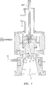
- Figure 1 describes a differential mobility analyzer for separating particles or ions suspended in a gas, comprising: an analyzing region (13) in which ions are injected through slit (4) into a flow of ion-free sheath gas. This flow is introduced in (1) and is made highly laminar by passage through several screens (2, 3) of high uniformity, and then by acceleration through a converging section (5). The ions are injected into the analyzing section (13) from an inlet chamber (12) whose cross section and slit width (4) are designed so as to provide a relatively uniform ion stream along the length of the slit.
- the ions may be introduced from the outside through port (16) into the inlet chamber (12), or may be produced there by means of a charging device from volatile species ingested through port (16).
- a charging device from volatile species ingested through port (16).
- Such a charger is incorporated in figure 1 in the form of a strip of 63 Ni (15).
- At least two electrodes or grids (14 and 6) spaced apart from each other and charged to different voltages create an electric field in the analyzing region (13), which displaces the ions injected in (4) accross streamlines, and directs those having certain desired electrical mobilities into one or several collecting or sampling devices, such as the sampling slit (7).
- the apparatus further comprises a flow constriction leading to a nozzle (8).
- this nozzle (8) serves the purpose of isolating the working region (13) from other regions further downstream, in order to avoid or reduce perturbations on the axisimmetry of steadiness of the flow in the working region.
- This constriction (8) is nonetheless moderate in the present invention in order to minimize pressure drop through the apparatus, thereby enabling attaining reatively high velocities and Reynolds numbers.
- a first exhaust chamber (9) is provided downstream from the throat (8), which is in turn connected by means of at least three symmetrically placed tubes (10) (only two are shown in Figure 1 , of the ten actually present in the prototyple rendered) to a second exhaust chamber (11).
- the intent of such buffers between the working region (13) and the exhaust line (17) going to the pump is to avoid propagation upstream of the flow assymetries existing on the downstream end of the instrument, but to do so with a relatively small pressure drop. Loss of axisymmetry in the working region would be fatal to resolution.
- Prior art has made use of only one sheath gas exhaust port.
- a secondary exhaust chamber (11) acts as a manifold that collects the various streams from the primary exhaust chamber into a single final exhaust port (17).
- the dimensions of the second exhaust chamber (11) are also such that the angular variations of pressure are small compared to the already small pressure drop along each of the ten exhaust lines.
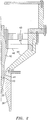
- Figure 2 describes an embodiment of the instant invention, where the exhaust system is completely axisymmetric and no constriction is introduced upstream of the diffuser (33, 38).
- a slowly diverging diffuser following the sampling slit (40) enables substantial pressure recovery.
- This diffuser (33, 38) is essential in order to approach sonic conditions at the throat with high efficiency household vacuum cleaner motors, whose maximum pressure rise is generally well below 1/2 of an atmosphere, even in tightly encased two-stage systems.
- the apparatus differs principally from that described in figure 1 in the need to suspend the central electrode (42) from upstream, rather than downstream of the working section.
- Its support is a perforated piece (43), which also supports the outer elements of the DMA, including the laminarizing trumpet (44) and the laminarization screens (45, 46).
- flow diffusion is achieved by introducing divergence not only in the final region of the inner electrode (33) but also at the end region of the outer electrode (38). But divergence in only one electrode would often suffice.
- the conventional criterion allowing diffuser semi-angles up to 3.5 degrees may not necessarily be appropriate under present conditions, as the inlet flow differs from the standard designs in being initially laminar rather than turbulent, which makes the flow far more prone to separate from the walls, reducing drastically diffuser efficiency.
- the exhaust line is completely axysimmetric and can be integrated directly to a high flow pump such as those commercialized by AMETEK (lamb electric division) for household or industrial central vacuum systems.
- Such levels can be attained with a moderately small inlet trumpet, such as that employed in the Vienna DMA, and do not require use of the large trumpet inlet proposed in U.S. Patent No. 5,869,831 .
- large inlet trumpets have the desirable advantage of reducing free stream turbulence, they are by far the bulkiest, heaviest and most expensive component of the DMA. It is therefore wise to avoid their use whenever such high degrees of laminarization are not absolutely essential to assure proper DMA performance.
- Free stream turbulence levels of 1% are certainly compatible with the attainment of resolutions of the order of 100, better than the current world record (close to 70) reached with a DMA provided with a large trumpet inlet but no converging working section.
- FIG. 1 One example of the proposed converging DMA concept is shown in Figure 1 for the case of an axisymmetric DMA. They combine particle-free fluid flow (the sheath gas introduced through (1)) and electric fields to drive charged particles introduced through a first narrow slit (the inlet or injection slit (4)) located in a first electrode or grid (14) into a second narrow slit or collector device (the outlet or sampling slit (7)) located in a second electrode or grid (6). The space between these two slits and electrodes will be referred to as the "working section" of the DMA. A particle-free sheath gas is introduced into a fluid flow inlet (1).
- aspiration counters differ in many ways from DMAs, since the full flow rather than a small part of it carries charged particles. This makes it undesirable to use a large laminarization chamber with inlet filters and screens, so that convergence in the working region is more necessary than in DMAs. Aspiration counters do not have either an injection slit, so that the stabilization requirements in these instruments are considerably milder than in DMAs.
- Labowsky's design differs from the geometries considered in de la Mora (2002) in that the boundary conditions for the stream function and the electrical potential do no longer coincide with each other at the plane of symmetry.
- certain special precautions are necessary.
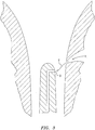
- One possible approach is to lower the bullet nose from its traditional position (well above the inlet slit) into a region closer to the inlet slit, or downstream from it, where its electric field is felt by the ions as they emerge through the inlet slit.
- the axisymmetric analog of Figure 3 provides another example where the same advantage arises. Again, the advantage requires certain unusual features, such as the proximity characteristic mentioned, which are not met by any axisymmetric or two-dimensional DMA built to date.
- the embodiment of the present invention accelerates the flow by a combination of various degrees of convergence on the outer and inner electrodes.
- U.S. Patent Nos. 5,869,831 and 5,936,242 protect DMAs with a laminarization system delivering a laminar flow at Reynolds numbers above 2000 into the working section inlet.
- the present invention covers situations where the laminarizing means provides laminar flows below 2000 to the inlet of the working section, but subsequent acceleration within the working section may increase considerably the Reynolds number in downstream regions of the working section.
- considerable acceleration (hence increase in Re) can be achieved in axisymmetric geometries with acceptable resolution loss.
- Another embodiment of the present invention comprises a method to achieve better laminarization conditions at the beginning of the working section than previously obtained, even with a large inlet trumpet.
- This new method uses a small inlet trumpet, such as that in the Vienna or the Rosell DMAs.
- the flow passing the inlet screen becomes turbulent.
- This turbulence survives for a certain distance downstream, which appears as undesirable from the viewpoint of achieving a highly laminar flow
- this turbulence provides excellent mixing, and the flow becomes highly uniform on the average.
- the introduction of turbulence in the screen is desirable rather than undesirable as it yields a highly uniform as well as a highly laminar flow.
- the present improvement therefore involves (a) choosing a screen cross-section, transparency, and wire diameter such that (at a given gas flow rate) the flow through the screen becomes turbulent.
- the criterion for this to happen is well known to fluid dynamicists, and involves a Reynolds number about the screen wire larger than about 40, (based on local speed and wire diameter), when the Karman vortex street sets in; (b) Using a moderately converging geometry following the screens, such that, if the flow were laminar, it would remain laminar, while a turbulent flow would tend to relaminarize; and (c) Choosing a sufficiently long distance between the screen and the aerosol inlet slit, and making the screen wires and opening sufficiently small for the turbulent flow to actually relaminarize before it reaches the aerosol inlet slit.
- relaminarization at high flow Re in the channel requires a convergent wall, such as discussed in de la Mora (2002). But, as discussed, it does not require a high convergence angle, so that a relatively modest convergence ratio (such as that in the Reischl or the Rosell DMA) provides a relatively long path for relaminarization. Hence, it is preferable to use small convergence angles (yet large enough to assure flow stability as discussed in de la Mora (2002)) because this provides a greater downstream distance for relaminarization.
- the required relaminarization distance is well known to fluid dynamicists familiar with the field of grid turbulence.
- a disadvantage of the small over the large inlet trumpet is that a small screen area with a small screen transparency tends to produce high pressure drop, and hence yields a smaller flow rate with a given pump.
- the present invention includes a means to counteract this problem without making use of previous art based on large laminarization trumpets.
- the new procedure uses first a wide flow cross-section with one or several filters, and one first screen of low transparency (say 30%). The flow resistance is small in spite of the low transparency because the area is large. Then follows a convergent region, and finally the true laminarization screen with small cross section, as described in point 3.
- the difference with 3 is that this laminarization screen may have a large transparency and hence a low pressure drop, without loss of the advantages described in point 3.
- prior art used first a low transparency screen and a high transparency screen for laminarization, both in a large cross sectional area, followed by a convergent region.
- This arrangement is typical of wind tunnel inlet designs, and is widely used in fluid mechanical laboratories.
- the present invention uses a high cross-sectional area only for the upstream filters (if any) and the low transparency screen, and introduces the high transparency screen somewhere within the convergence region. It includes all the advantages described above without the disadvantage of the high pressure drop.
- Another preferred embodiment of the present invention is such that the maximum displacement of the axis of one cylinder from the axis of the other is less than one thousandth of an inch, preferably less than half a thousandth of an inch.
- Knutson The Distribution of Electric Charge Among the Particles of an Artificially Charged Aerosol, Ph.D. Thesis, University of Minnesota (1971) considers the effect that a parallel displacement ⁇ of the axis of one of the cylindrical electrodes with respect to the axis of the other cylinder has on DMA resolution. His numerical results for the particular case of the DMA disclosed in Knutson et al., Aerosol Classification by Electrical Mobility: Apparatus, Theory and Applications, J. Aerosol Sci., Vol. 6, pp.
- the DMA of Knutson et al. (1975) provides for an axisymmetric injection of the aerosol flow through the inlet slit.
- This design is associated to large losses of particles smaller than 5 nanometers by diffusion to the aerosol inlet walls.
- This problem is partly overcome by the split-flow design in the nanoDMA of Chen et al., Design and Numerical Modeling, presented at the AAAR Annual Meeting, Orlando, FL, Oct. 14-18 (1996 ), and Chen et al., Numerical Modeling of the Performance of DMAs for Nanometer Aerosol Measurement, J. Aerosol Sci., Vol. 28, pp. 985-1004 (1997 ).
- this design has not yet demonstrated an ability to transmit and size particles with diameters smaller than 3 nanometers.
- the Vienna DMA introduces the aerosol stream through a short lateral tube into an aerosol inlet chamber immediately preceding the inlet slit. Losses of very small particles are thereby greatly reduced with respect to truly axisymmetric designs, with a demonstrated ability to transmit even small ions. This improvement, however, comes at a cost.
- the inlet chamber (12) is annular or straight for cylindrical or two-dimensional DMAs, respectively, both cut on one side by the slit (4). The flow of aerosol through the slit into the working chamber is driven by the difference in pressure of the gas upstream and downstream the slit.
- the aerosol injection chamber is designed in the present invention such that the pressure drop along the perimeter of the chamber is much smaller than the pressure drop across the slit. This goal is achieved by making the cross section of the chamber sufficiently large and the injection slit channel sufficiently narrow and long.
- the slit width of the DMA shown in Figure 1 can be changed by inserting shimstock pieces at the union of the two pieces defining the slit.
- Another consideration suggesting the use of larger rather than smaller inlet slit widths is the fact that diffusion losses increase as l/ ⁇ i .
- the variable slit design of this instrument therefore allows its widening in cases when the signal is too small, and a reduction of transmission losses carries more weight than other considerations.
- the ideal range in this invention for the vertical elevation of the inlet slit top over its bottom is between 0.025 ⁇ and 0.1 ⁇ , with a preferred value of 0.05 ⁇ .
- the dimensions of the aerosol chamber preceding the inlet slit in the cylindrical DMA of Figure 1 have been determined such as to meet the requirements of the previous paragraph using the preferred elevation of 0.05 ⁇ .
- An excessive chamber cross section is undesirable because it would promote the loss of small charged particles by space charge.
- a serious difficulty associated to axisymmetric DMAs is the relatively high loss of nanometer particles through its inlet up to the point past the aerosol injection slit. Such losses are particularly high in the case of intense sources of unipolarly charged particles, such as electrosprays.
- a solution to this problem was proposed in U.S. Patent No. 5,869,831 involving a planar DMA configuration with two orifices rather than two slits. That principle can be used similarly in the case of DMAs with converging walls, and is thereby incorporated into the present invention, either for mass spectrometric applications or for other purposes.
- Axisymmetric DMAs may therefore not be the most competitive instrument in dealing with certain analytical applications with intense unipolar ion sources at atmospheric pressure.
- situations such as monitoring of explosives or drugs where the volatile species to be detected are initially neutral, there would be no loss of analyte at the inlet of the DMA.
- a neutral analyte is volatile at temperatures higher than that at the DMA inlet line, losses by diffusion may still exist, but the generally stronger losses associated to space charge would still be absent.
- an axisymmetric DMA geometry such as that shown in Figure 1 offers advantages over the two orifices placed in two parallel or converging walls just discussed in relation to U.S. Patent No. 5,869,831 .
- the reason is that, at sheath air flow rates of 3000 liters/minute, the aerosol flow could, without loss of resolution, be as high as 30-60 liters/minute.
- This flow rate is vast compared to the throughput that can be passed through a typical atmospheric pressure inlet to a mass spectrometer, and would be ideally suited for situations involving highly dilute and difficult to detect analytes.
- the species to be detected would be charged in the aerosol inlet chamber, immediately upstream of the injection slit, thereby minimizing the loss of analyte ions by diffusion to the walls once they are formed.
- a variety of schemes can be used for the purpose of charging the analyte vapor molecules, including a radioactive source placed through the whole or a portion of the perimeter of the aerosol inlet chamber (for instance, a ring or a washer of 63 Ni, 210 Po, or another alpha or beta emitter).
- this invention also includes variously converging axisymmetric DMAs with a radioactive source spread over all or part of its aerosol inlet chamber.
- charging schemes other than those relying on radioactive sources are also included within the scope of this invention. In fact, Ion Mobility Spectrometry; by Eiceman et al.
- Another objective of this invention is to identify conditions enabling the construction of DMAs enjoying both wide size range and high resolution operation.
- the short DMA of Rosell et al. (1996) has a length L approximately twice the optimal value L*, and achieves as a result a resolution in the nanometer range substantially higher than the similar but much longer Vienna DMA, where L/L* is close to 15.
- MALDI Matrix assisted laser desorbtion ionization mass spectrometry
- MALDI Matrix assisted laser desorbtion ionization mass spectrometry
- the ionization process is strongly dependent on polymer mass as well as the chemical nature of the analyte and the matrix, which makes problematic the quantitation of polymer mass distributions over their typically broad mass ranges.
- the masses in the related problem of protein or nucleic acid analysis range similarly from several thousand amu, up to several millions. This situation is often, but not always, amenable to electrospray mass spectrometric investigation, and would also benefit from the availability of alternative fast and inexpensive techniques such as that provided by DMAs.
- DMAs have a much higher mass range than mass spectrometers, the procedure of reducing to unity the charge of electrospray ions is still compatible with their mobility classification at mass to charge values even beyond 10 7 amu. In these important two examples just mentioned, and probably in many others, it would be very useful to develop a DMA capable of covering at high resolution the whole size range, from at least 2 nanometers up to 30 nanometers.
- Equation (6) shows that, for a given cylindrical DMA geometry (given R 1 , R 2 and L), the smallest value of Z attainable (lowest mobility range) corresponds to the largest voltage and the smallest flow rate. Brownian motion is generally relatively weak in the small mobility region, so that the main factor limiting resolution (in mechanically and fluid dynamically well designed instruments) is the ratio q a /Q of aerosol to sheath air flows. Resolution is highest when the aerosol inlet flow is close to the aerosol outlet flow, and we will consider only this most favorable situation, where FWHH is equal to q a /Q. The resolution criterion that FWHH be smaller than 1% therefore fixes this flow rate ratio to be smaller than 1%.
- the group A/C takes the value 252 in the present estimate, but can be made considerably larger by relaxing the resolution requirement.
- the range of mobilities spanned by air-suspended particles with diameters going from 2 nanometers to 100 nanometers is considerably wider than 100, implying that it is not possible to cover it fully with a single instrument for the conditions of resolution, flow rates, voltages and temperature set here.
- one embodiment of the present invention capable of reaching high resolution over an unusually wide range of mobilities consists of a DMA where one of the electrodes is interchangeable, so that the variable b can take in one electrode configurations values in the vicinity of the optimal (1 ⁇ b ⁇ 4), and considerably larger values of the order of 10 in another electrode configuration.
- This method has been used by Rosell et al., (1993, 1996) in a DMA with the inner and outer diameters identical to those in the Vienna DMA.
- Another embodiment of the present invention is an axisymmetric DMA of fixed geometry approaching conditions for maximum range, with a preferred geometry such that b is near 3 and R 1 /R 2 > 0.56.
- a two-bullet DMA can also be implemented to widen the Z min range of an instrument such as that in Figure 2 , meant to cover the nanometer and subnanometer range.
- An alternative means to reduce free stream turbulence proposed in this invention is to introduce a substantial (rather than a slight) contraction within the working section. This approach differs from earlier art, where the working section was unaccelerated and the large contraction was placed upstream from it. This key difference leads for diverse reasons to variations in performance between the two approaches.
- the inlet trumpet is first concave and then convex, finishing in a direction parallel to the walls of the working section.
- the inlet trumpet is consequently rather long and heavy. Its length was decreased in the design of Herrmann by elimination of the initial concave part and by use of a conical inlet of relatively large angle ( Figure 2 ).
- the transition between this converging inlet and the non-converging working section must be gradual (therefore long) in order to avoid flow separation.
- the relatively long associated transition regions lead also to wide boundary layers at the aerosol inlet section, which precipitate transition. Most of these problems are eliminated by using a rapidly converging working section.
- the transition between both can be relatively short or entirely absent.
- the distance between the nozzle and the sampling slit can be made relatively short, since neither a straightening of the jet at the inlet of the exhaust chamber is needed, nor a change of curvature or slope immediately after the sampling slit.
- bk ⁇ 1 e ⁇ / k / ⁇ / k .
- the inner radius Shortly downstream the inlet slit, the inner radius would rise rapidly to its final radius of 4 mm, while the outer radius would continue converging through the working section at the same rate as ahead of the inlet slit, or at an even larger rate.
- the effective level of laminarization would then be comparable in both configurations, as would the diameter and effectiveness of the laminarization screens, as well as the sheath gas exhaust section and associated pumping requirements.
- the new DMA would, however, be considerably shorter than that based on U.S. Patent No. 5,869,831 . This would allow lengthening in the present invention the inlet region prior to the aerosol injection slit, thereby further dissipating the already small level of turbulence generated at the inlet screens or surviving through them.
- the level of convergence downstream the inlet slit would then be higher than upstream, with a particularly intense flow acceleration level therefore helping stabilizing the mixing layer.
- the very large Reynolds numbers of interest to this invention lead to substantially more intense acoustic fields, which can be heard very well, even when no resonance seems to be excited.
- the need for resolutions in the vicinity of 1% also makes the impact of small radiative effects potentially serious.
- This is a common problem in many flow systems, and can be alleviated by a variety of means, including geometrical and fluid dynamical design.
- the present invention includes the possibility to isolate completely the laminar working section from the acoustic radiation field from the inevitably turbulent sheath gas exhaust chamber by driving the flow to sonic conditions at the throat following the aerosol sampling slit.
- Another embodiment of the present invention would use a high speed subsonic flow through the whole analyzing region including a moderate distance downstream the aerosol sampling slit. The flow would then be accelerated to sonic and slightly supersonic conditions through the nozzle throat and beyond it, and the supersonic region would isolate the working region of the DMA from acoustic radiation from the highly perturbed flow present further downstream. A slight contraction will make the flow sonic in the throat and slightly supersonic thereafter, precluding completely the entry of any pressure fluctuations from downstream the throat into the sensitive analyzing section.
Landscapes
- Physics & Mathematics (AREA)
- Chemical & Material Sciences (AREA)
- Health & Medical Sciences (AREA)
- Life Sciences & Earth Sciences (AREA)
- Analytical Chemistry (AREA)
- Spectroscopy & Molecular Physics (AREA)
- Chemical Kinetics & Catalysis (AREA)
- Electrochemistry (AREA)
- Molecular Biology (AREA)
- Biochemistry (AREA)
- General Health & Medical Sciences (AREA)
- General Physics & Mathematics (AREA)
- Immunology (AREA)
- Pathology (AREA)
- Other Investigation Or Analysis Of Materials By Electrical Means (AREA)
Claims (18)
- Verfahren zum Trennen geladener Partikel oder Ionen in einem differentiellen Mobilitätsanalysator, wobei ein Strom von geladenen Partikeln oder Ionen in einen stromaufwärtigen Abschnitt einer Analyseregion (13) durch einen Einlassschlitz bzw. eine Einlassöffnung (4) eingeführt wird und wobei eine Kombination aus einem laminaren Flussfeld und einem elektrischen Feld bewirkt, dass sich Ionen mit unterschiedlichen Mobilitäten im Raum trennen, das Verfahren umfassend die folgenden Schritte:(a) das Einführen eines Stroms von geladenen Partikeln oder Ionen mit verschiedenen elektrischen Mobilitäten in die Analyseregion (13);(b) das Laminarisieren eines Flusses aus einem ionenfreien Hüllgas und das Einführen des Hüllgases in den differentiellen Mobilitätsanalysator unmittelbar stromaufwärts von der Analyseregion (13);(c) das Aufrechterhalten des Flusses aus dem Hüllgas in der Analyseregion (13) als laminaren Fluss;(d) das Bereitstellen eines elektrischen Feldes in der Analyseregion (13) durch eine Kombination aus mit verschiedenen Spannungen geladenen Elektroden und Gittern (14, 42) und Ladevorrichtungen, um die verschiedenen Spannungen der Elektroden und Gitter aufrechtzuerhalten;(e) das Abtasten oder Sammeln der getrennten Partikel oder Ionen innerhalb eines schmalen Bereichs von elektrischen Mobilitäten durch mindestens eine Abtast- oder Sammlervorrichtung (40), von denen die letzte den Ausgang der Analyseregion (13) definiert,wobei der differentielle Mobilitätsanalysator des Weiteren dadurch gekennzeichnet ist, dass dieser umfasst:
wobei der differentielle Mobilitätsanalysator enthält:einen Laminarisierungstrichter (44) und Laminarisierungssiebe (45, 46) zur Bereitstellung eines laminaren Flusses von ionenfreiem Hüllgas in ein stromaufwärtiges Ende der Analyseregion (13);Ionen-Zuführeinrichtungen (4, 12, 15, 16) zum Einführen der Ionen und geladenen Partikel in die Analyseregion (13);mindestens zwei Elektroden oder Gitter (14, 42), umfassend eine äußere Elektrode (14) und eine innere Elektrode (42), die auf geeignete Potenziale geladen sind, um ein elektrisches Feld innerhalb der Analyseregion (13) zu erzeugen;wodurch die Ionen durch die kombinierte Wirkung des elektrischen Feldes und des Flusses aus Hüllgas im Raum getrennt werden;mindestens eine Abtast- oder Sammelvorrichtung (40), durch welche Ionen einer gewünschten Mobilität abgetastet oder gesammelt werden; undStromversorgungseinrichtungen zum Laden der mindestens zwei Elektroden oder Gitter (14, 42) auf die Potenziale,(i) einen divergenten Diffusor (33, 38) und ein Halsstück (8), die stromabwärts von der Analyseregion (13) positioniert sind;(ii) ein perforiertes Stück (43) zur Stützung der inneren Elektrode (42) stromaufwärts von der Analyseregion (13), wobei das perforierte Stück (43) auch den Laminarisierungstrichter (44) und die Laminarisierungssiebe (45, 46) stützt. - Verfahren gemäß Anspruch 1, wobei der Fluss des Hüllgases in einer Eintrittsregion, wo er auf den Einlassstrom von Ionen trifft, als ein laminarer Fluss aufrechterhalten wird, indem ein Querschnitt des Flusses in einer Nähe der Eintrittsregion reduziert wird, um den Fluss lokal zu beschleunigen.
- Verfahren gemäß Anspruch 1, wobei die Differenz zwischen dem elektrischen Potenzial, das an mindestens eine der Elektroden (14) in elektrischem Kontakt mit dem Einlassschlitz (4) angelegt wird, und dem elektrischen Potenzial, das an mindestens eine der Abtast- oder Sammlerelektroden angelegt wird, auf kleine Werte (42) reduziert ist.
- Verfahren gemäß Anspruch 1, wobei mindestens eine Abtast- oder Sammelvorrichtung (40) eine Mehrzahl von Sammlervorrichtungen umfasst.
- Verfahren gemäß Anspruch 1, wobei der Fluss des ionenfreien Hüllgases durch Positionierung einer Strömungsverengung oder eines Halsstücks zwischen dem Ausgang der Analyseregion (13) und dem Einlass des Diffusors (33, 38) verengt wird.
- Verfahren gemäß Anspruch 1, wobei der Strom aus geladenen Partikeln oder Ionen durch Ionisierung bereits existierender flüchtiger Substanzen stromaufwärts von dem Einlassschlitz (4) erzeugt wird.
- Verfahren gemäß Anspruch 6, wobei die Partikel oder Ionen mit einer radioaktiven Quelle (15) geladen werden, wobei die radioaktive Quelle aus der Gruppe ausgewählt ist, welche 63Ni, 210Po und andere Alpha- und Beta-Strahler umfasst, oder wobei die Partikel oder Ionen mithilfe von Elektrosprühen geladen werden.
- Verfahren gemäß Anspruch 1, wobei die Analyseregion (13) von der stromabwärtigen akustischen Strahlung isoliert ist, indem der Fluss in einer Region zwischen der mindestens einen Sammlervorrichtung (40) und dem Diffusor (33, 38) bewirkt wird, um die Schallgeschwindigkeit zu erreichen.
- Verfahren gemäß Anspruch 1, wobei die Auflösung des differentiellen Mobilitätsanalysators erhöht wird, indem eine Aerosol-Injektionskammer (12) stromaufwärts von dem Einlassschlitz (4) ausgebildet ist, sodass der Druckabfall für den Fluss des Stroms aus geladenen Partikeln oder Ionen entlang einer Länge des Einlassschlitzes (4) wesentlich kleiner ist als bei dessen Fluss über den Einlassschlitz (4).
- Differentieller Mobilitätsanalysator zum Trennen von in einem Gas suspendierten Ionen und geladenen Partikeln, umfassend:einen Laminarisierungstrichter (44) und Laminarisierungssiebe (45, 46) zur Bereitstellung eines laminaren Flusses von ionenfreiem Hüllgas in ein stromaufwärtiges Ende einer Analyseregion (13);Ionen-Zuführeinrichtungen (4, 12, 15, 16) zum Einführen der Ionen und geladenen Partikel in die Analyseregion (13);mindestens zwei Elektroden oder Gitter (14, 42) umfassend eine äußere Elektrode (14) und eine innere Elektrode (42), die auf geeignete Potenziale geladen sind, um ein elektrisches Feld innerhalb der Analyseregion (13) zu erzeugen;wodurch die Ionen durch die kombinierte Wirkung des elektrischen Feldes und des Flusses aus Hüllgas im Raum getrennt werden;mindestens eine Abtast- oder Sammelvorrichtung (40), welche den Ausgang der Analyseregion (13) definiert, durch welche Ionen einer gewünschten Mobilität abgetastet oder gesammelt werden; undStromversorgungseinrichtungen zum Laden der mindestens zwei Elektroden oder Gitter (14, 42) auf die Potenziale,dadurch gekennzeichnet, dass der differentielle Mobilitätsanalysator des Weiteren umfasst:(i) einen divergenten Diffusor (33, 38) und ein Halsstück, die stromabwärts von der Analyseregion (13) positioniert sind;(ii) ein perforiertes Stück (43) zur Stützung der inneren Elektrode (42) stromaufwärts von der Analyseregion (13), wobei das perforierte Stück (43) auch den Laminarisierungstrichter (44) und die Laminarisierungssiebe (45, 46) stützt.
- Differentieller Mobilitätsanalysator gemäß Anspruch 10, wobei die Differenz zwischen dem elektrischen Potenzial, das an mindestens eine der in elektrischem Kontakt mit dem Einlassschlitz (4) stehenden Elektroden (14) angelegt wird, und dem elektrischen Potenzial, das an mindestens eine der Abtast- oder Sammlerelektroden (40) angelegt wird, auf kleine Werte reduziert ist.
- Differentieller Mobilitätsanalysator gemäß Anspruch 10, wobei die mindestens eine Abtast- oder Sammelvorrichtung (40) eine Mehrzahl von Sammlervorrichtungen umfasst.
- Differentieller Mobilitätsanalysator gemäß Anspruch 10, wobei die Ionen-Zuführeinrichtungen zum Einführen der Ionen und geladenen Partikel in die Analysekammer umfassen: eine Einlasskammer (12), die über einen Einlassschlitz bzw. eine Einlaßöffnung (4) mit der Analyseregion kommuniziert, ein stromabwärtiges Ende des Laminarisierungstrichters (44) und der Laminarisierungssiebe (45, 46) zur Bereitstellung eines laminaren Flusses von ionenfreiem Hüllgas in das stromaufwärtige Ende der Analyseregion (13), der konvergiert, bis er auf den Einlassschlitz bzw. die Einlassöffnung (4) trifft;
- Differentieller Mobilitätsanalysator gemäß Anspruch 13, enthaltend Einrichtungen zur lokalen Beschleunigung des Flusses in einer Eintrittsregion der Analyseregion (13) an einer Stelle, wo das partikelfreie Hüllgas auf den Einlassstrom von Partikeln oder Ionen trifft, wobei die Einrichtungen zur lokalen Beschleunigung das Reduzieren des Querschnitts des Flusses umfassen.
- Differentieller Mobilitätsanalysator gemäß Anspruch 10, umfassend eine Auslasskammer (9), die stromabwärts von der Analyseregion (13) positioniert ist, wobei die Auslasskammer (9) durch mindestens zwei symmetrisch platzierte Auslassrohre (10) mit einer stromabwärtigen Pumpkammer verbunden ist.
- Differentieller Mobilitätsanalysator gemäß Anspruch 10, wobei eine der mindestens zwei Elektroden ihre Anströmkante stromabwärts von dem Einlassschlitz (4) hat, um die Diffusionsausweitung zu minimieren.
- Differentieller Mobilitätsanalysator gemäß Anspruch 10, wobei die Einrichtungen zur Bereitstellung eines laminaren Flusses von ionenfreiem Hüllgas in das stromaufwärtiges Ende einer Analyseregion (13) das Durchleiten des Hüllgases durch mindestens einen Filter und mindestens ein Sieb (45, 46) umfassen, und anschließend dessen Beschleunigung durch eine konvergierende Region (44) hindurch, wobei vorzugsweise das Sieb (46) von dem mindestens einen Sieb, das sich am meisten stromabwärts befindet, den Fluss turbulent macht, indem es über einer kritischen Reynolds-Zahl arbeitet, die notwendig ist, um eine Siebturbulenz zu erzeugen, und wobei dieser turbulente Fluss nachfolgend in der konvergierenden Region (44) relaminarisiert wird.
- Differentieller Mobilitätsanalysator gemäß Anspruch 10, wobei der Strom aus geladenen Partikeln oder Ionen durch Ionisierung bereits existierender flüchtiger Substanzen in einem Raum (12), der stromaufwärts von dem Einlassschlitz (4) angeordnet ist, durch geeignete Ladeeinrichtungen (15) erzeugt wird.
Applications Claiming Priority (3)
| Application Number | Priority Date | Filing Date | Title |
|---|---|---|---|
| US32414301P | 2001-11-02 | 2001-11-02 | |
| US324143P | 2001-11-02 | ||
| PCT/US2002/035020 WO2003041114A2 (en) | 2001-11-02 | 2002-11-01 | Method and apparatus to increase the resolution and widen the range of differential mobility analyzers (dmas) |
Publications (3)
| Publication Number | Publication Date |
|---|---|
| EP1446820A2 EP1446820A2 (de) | 2004-08-18 |
| EP1446820A4 EP1446820A4 (de) | 2008-09-24 |
| EP1446820B1 true EP1446820B1 (de) | 2017-03-15 |
Family
ID=23262277
Family Applications (1)
| Application Number | Title | Priority Date | Filing Date |
|---|---|---|---|
| EP02782256.8A Expired - Lifetime EP1446820B1 (de) | 2001-11-02 | 2002-11-01 | Verfahren und vorrichtung zur vergrösserung der auflösung und des bereichs von differenz-mobilitätsanalysierern |
Country Status (7)
| Country | Link |
|---|---|
| US (2) | US6787763B2 (de) |
| EP (1) | EP1446820B1 (de) |
| JP (1) | JP2005509256A (de) |
| AU (1) | AU2002348333B2 (de) |
| CA (1) | CA2465166A1 (de) |
| IL (1) | IL161613A0 (de) |
| WO (1) | WO2003041114A2 (de) |
Families Citing this family (40)
| Publication number | Priority date | Publication date | Assignee | Title |
|---|---|---|---|---|
| JP3349965B2 (ja) * | 1998-11-05 | 2002-11-25 | 松下電器産業株式会社 | 微粒子分級方法及び装置 |
| EP1446820B1 (de) * | 2001-11-02 | 2017-03-15 | Yale University | Verfahren und vorrichtung zur vergrösserung der auflösung und des bereichs von differenz-mobilitätsanalysierern |
| US6861646B2 (en) * | 2002-02-15 | 2005-03-01 | Implant Sciences Corporation | Cyclone sampling nozzle for an ion mobility spectrometer |
| US8122756B2 (en) * | 2002-02-15 | 2012-02-28 | Implant Sciences Corporation | Narcotics and explosives particle removal system |
| ES2206019B1 (es) * | 2002-04-11 | 2005-07-16 | Consejo Sup. Investig. Cientificas | Procedimiento para la mejora de la resolucion del analizador diferencial de movilidad electrica mediante el intercambio de los flujos de entrada. |
| US7208727B2 (en) * | 2003-01-14 | 2007-04-24 | Georgia Tech Research Corporation | Electrospray systems and methods |
| WO2004077016A2 (en) | 2003-02-22 | 2004-09-10 | Labowsky Michael J | Ion mobility separation devices |
| US20050109856A1 (en) * | 2003-11-25 | 2005-05-26 | Alexander James N.Iv | Method for preparing polymer electrosprays |
| KR100567788B1 (ko) * | 2004-02-13 | 2006-04-05 | 주식회사 현대교정인증기술원 | 입자측정기 및 입자측정방법 |
| US7213476B2 (en) * | 2005-05-31 | 2007-05-08 | Ut-Battelle, Llc | Stackable differential mobility analyzer for aerosol measurement |
| AT502207B1 (de) * | 2005-08-05 | 2007-11-15 | Univ Wien | Verfahren zum klassifizieren und trennen von teilchen sowie vorrichtung zur durchführung dieses verfahrens |
| DE602005026063D1 (de) * | 2005-08-18 | 2011-03-03 | Ramem S A | Differentieller mobilitätsanalysator (dma) mit breitem spektrum und sehr hoher auflösung |
| US7521673B2 (en) * | 2005-08-24 | 2009-04-21 | Rahem, S.A. | Wide range, very high resolution differential mobility analyzer (DMA) |
| FI119660B (fi) * | 2005-11-30 | 2009-01-30 | Environics Oy | Kaasun ioniliikkuvuuden mittausmenetelmä ja -laite |
| US8884221B2 (en) * | 2006-01-05 | 2014-11-11 | Excellims Corporation | High performance ion mobility spectrometer apparatus and methods |
| US7928374B2 (en) * | 2006-04-10 | 2011-04-19 | Sociedad Europea de Analisis Diferencial de Movilidad | Resolution improvement in the coupling of planar differential mobility analyzers with mass spectrometers or other analyzers and detectors |
| US7909897B2 (en) * | 2006-11-28 | 2011-03-22 | Georgia Tech Research Corporation | Droplet impingement chemical reactors and methods of processing fuel |
| WO2008101998A2 (en) * | 2007-02-24 | 2008-08-28 | Sociedad Europea De Análisis Diferencial De Movilidad, S.L. | Method to accurately discriminate gas phase ions with several filtering devices in tandem |
| EP2145345A2 (de) * | 2007-04-23 | 2010-01-20 | Fernandez de la Mora, Juan | Verbesserte kopplung zwischen axialsymmetrischen differenziellen mobilitätsanalysatoren und massenspektrometern oder anderen analysatoren und detektoren |
| US8217345B2 (en) * | 2007-10-18 | 2012-07-10 | Dh Technologies Development Pte. Ltd. | Interface between differential mobility analyzer and mass spectrometer |
| US7858927B2 (en) * | 2007-11-23 | 2010-12-28 | Dh Technologies Development Pte, Ltd. | Apparatus and method for operating a differential mobility analyzer with a mass spectrometer |
| KR101524896B1 (ko) * | 2008-02-06 | 2015-06-01 | 바스프 에스이 | 다차원적 에어로졸 특성화를 위한 측정 시스템 |
| ES2350132B1 (es) * | 2008-02-14 | 2011-10-21 | Centro De Investigaciones Energeticas Medioambientales Y Tecnologicas (Ciemat) | Sistema para disminuir la caida de presion en un analizador por movilidad electrica (dma). |
| CN101587815B (zh) * | 2008-05-19 | 2011-12-21 | 同方威视技术股份有限公司 | 双面离子源 |
| US20100031734A1 (en) * | 2008-08-05 | 2010-02-11 | Nitto Denko Corporation | Method and system for detecting impurities in liquids |
| US8071940B2 (en) * | 2009-08-13 | 2011-12-06 | Centro De Investigaciones Energeticas, Medioambientales Y Tecnologicas | System to reduce the pressure drop in a differential mobility analyzer |
| US20120235033A1 (en) * | 2009-11-11 | 2012-09-20 | Emilio Ramiro Arcas | Differential mobility analyzer |
| US7992454B2 (en) * | 2009-12-04 | 2011-08-09 | International Business Machines Corporation | Airflow bench with laminar flow element |
| US9239279B1 (en) | 2011-06-03 | 2016-01-19 | Arkansas State University—Jonesboro | Sequential differential mobility analyzer and method of using same |
| JP6278895B2 (ja) * | 2011-12-15 | 2018-02-14 | アカデミア シニカAcademia Sinica | 周期場微分型電気移動度分析装置 |
| JP5975100B2 (ja) | 2012-06-06 | 2016-08-23 | 株式会社島津製作所 | 微粒子分級測定装置、粒子濃度分布が一様なサンプル作成装置、及びナノ粒子膜成膜装置 |
| US9157871B2 (en) | 2012-07-11 | 2015-10-13 | Met One Instruments, Inc. | Method and apparatus to enhance collection of particles in particulate mass measurement device |
| GB2515285A (en) | 2013-06-17 | 2014-12-24 | Particle Measuring System Inc | A method for obtaining aerosol particle size distributions |
| RU2675879C2 (ru) * | 2014-09-26 | 2018-12-25 | Российская Федерация, от имени которой выступает Федеральное государственное казенное учреждение "Войсковая часть 68240" | Способ дистанционного отбора воздушных проб с поверхности и из негерметизированных объектов и устройство для его реализации |
| GB2560565B (en) * | 2017-03-16 | 2022-02-16 | Ancon Tech Limited | An ion selecting device for identification of ions in gaseous media |
| GB201810273D0 (en) | 2018-06-22 | 2018-08-08 | Thermo Fisher Scient Bremen Gmbh | Structural analysis of ionised molecules |
| DE112019006947B4 (de) * | 2019-03-01 | 2023-09-28 | Shimadzu Corporation | Matrixschichtaufbringungssystem und Matrixschichtaufbringungsverfahren |
| US12529679B2 (en) | 2021-05-14 | 2026-01-20 | Thermo Finnigan Llc | Flow recirculation for mobility separation improvement |
| CN115356242A (zh) * | 2022-07-29 | 2022-11-18 | 中国科学院合肥物质科学研究院 | 一种用于10-30nm高温尾气颗粒物的粒径快速分级装置及方法 |
| CN121114333B (zh) * | 2025-08-15 | 2026-03-31 | 复旦大学 | 3纳米以下中性团簇粒径分布和化学组分分析系统及方法 |
Citations (2)
| Publication number | Priority date | Publication date | Assignee | Title |
|---|---|---|---|---|
| US4769609A (en) * | 1986-09-19 | 1988-09-06 | Senichi Masuda | Measurement of ultra-fine particles utilizing pulsed corona signals |
| US5869831A (en) * | 1996-06-27 | 1999-02-09 | Yale University | Method and apparatus for separation of ions in a gas for mass spectrometry |
Family Cites Families (6)
| Publication number | Priority date | Publication date | Assignee | Title |
|---|---|---|---|---|
| US5218203A (en) * | 1991-03-22 | 1993-06-08 | Georgia Tech Research Corporation | Ion source and sample introduction method and apparatus using two stage ionization for producing sample gas ions |
| US5596136A (en) * | 1995-07-27 | 1997-01-21 | California Institute Of Technology | Radial differential mobility analyzer |
| JP3466416B2 (ja) * | 1997-04-16 | 2003-11-10 | 理化学研究所 | 微分型電気移動度測定器 |
| JP3487756B2 (ja) * | 1998-03-17 | 2004-01-19 | 理化学研究所 | 微分型電気移動度測定器 |
| JP3503931B2 (ja) * | 1999-08-04 | 2004-03-08 | 独立行政法人理化学研究所 | 微分型電気移動度分析器および微粒子処理装置 |
| EP1446820B1 (de) * | 2001-11-02 | 2017-03-15 | Yale University | Verfahren und vorrichtung zur vergrösserung der auflösung und des bereichs von differenz-mobilitätsanalysierern |
-
2002
- 2002-11-01 EP EP02782256.8A patent/EP1446820B1/de not_active Expired - Lifetime
- 2002-11-01 US US10/286,672 patent/US6787763B2/en not_active Expired - Lifetime
- 2002-11-01 AU AU2002348333A patent/AU2002348333B2/en not_active Ceased
- 2002-11-01 WO PCT/US2002/035020 patent/WO2003041114A2/en not_active Ceased
- 2002-11-01 CA CA002465166A patent/CA2465166A1/en not_active Abandoned
- 2002-11-01 JP JP2003543060A patent/JP2005509256A/ja active Pending
- 2002-11-01 IL IL16161302A patent/IL161613A0/xx unknown
-
2004
- 2004-08-20 US US10/923,623 patent/US7161143B2/en not_active Expired - Lifetime
Patent Citations (2)
| Publication number | Priority date | Publication date | Assignee | Title |
|---|---|---|---|---|
| US4769609A (en) * | 1986-09-19 | 1988-09-06 | Senichi Masuda | Measurement of ultra-fine particles utilizing pulsed corona signals |
| US5869831A (en) * | 1996-06-27 | 1999-02-09 | Yale University | Method and apparatus for separation of ions in a gas for mass spectrometry |
Also Published As
| Publication number | Publication date |
|---|---|
| US6787763B2 (en) | 2004-09-07 |
| EP1446820A2 (de) | 2004-08-18 |
| IL161613A0 (en) | 2004-09-27 |
| CA2465166A1 (en) | 2003-05-15 |
| US7161143B2 (en) | 2007-01-09 |
| WO2003041114A2 (en) | 2003-05-15 |
| JP2005509256A (ja) | 2005-04-07 |
| US20030116708A1 (en) | 2003-06-26 |
| EP1446820A4 (de) | 2008-09-24 |
| AU2002348333B2 (en) | 2007-02-01 |
| US20050045818A1 (en) | 2005-03-03 |
| WO2003041114A3 (en) | 2004-02-26 |
Similar Documents
| Publication | Publication Date | Title |
|---|---|---|
| EP1446820B1 (de) | Verfahren und vorrichtung zur vergrösserung der auflösung und des bereichs von differenz-mobilitätsanalysierern | |
| AU2002348333A1 (en) | Method and apparatus to increase the resolution and widen the range of differential mobility analyzers (DMAS) | |
| EP2463891B1 (de) | Miniaturmassenspektrometersystem | |
| EP1856714B1 (de) | Verfahren und vorrichtung zur empfindlichkeitsverstärkung in einem massenspektrometer | |
| US5936242A (en) | Method and apparatus for separation of ions in a gas for mass spectrometry | |
| CN1225006C (zh) | 纵向场驱动场致非对称离子迁移过滤器和检测系统 | |
| US7928374B2 (en) | Resolution improvement in the coupling of planar differential mobility analyzers with mass spectrometers or other analyzers and detectors | |
| US7256395B2 (en) | Method and apparatus for improved sensitivity in a mass spectrometer | |
| US8232519B2 (en) | Coupling between axisymmetric differential mobility analyzers and mass spectrometers or other analyzers and detectors | |
| US6827761B2 (en) | Particle concentrator | |
| CN101881752B (zh) | 微型二维离子迁移谱仪 | |
| JP2006523007A (ja) | 直交流型イオン移動度分析器 | |
| CN1099594C (zh) | 与液相色谱仪联用的质谱装置和质谱分析方法 | |
| US4769609A (en) | Measurement of ultra-fine particles utilizing pulsed corona signals | |
| CN109085097B (zh) | 一种集成荷电和分级技术的超细颗粒物分析器 | |
| US9324552B2 (en) | Periodic field differential mobility analyzer | |
| EP1923699B1 (de) | Differentieller mobilitätsanalysator (dma) mit breitem spektrum und sehr hoher auflösung | |
| WO2026037501A1 (en) | Apparatus | |
| CN118016512A (zh) | 一种质谱离子源装置 |
Legal Events
| Date | Code | Title | Description |
|---|---|---|---|
| PUAI | Public reference made under article 153(3) epc to a published international application that has entered the european phase |
Free format text: ORIGINAL CODE: 0009012 |
|
| 17P | Request for examination filed |
Effective date: 20040428 |
|
| AK | Designated contracting states |
Kind code of ref document: A2 Designated state(s): AT BE BG CH CY CZ DE DK EE ES FI FR GB GR IE IT LI LU MC NL PT SE SK TR |
|
| AX | Request for extension of the european patent |
Extension state: AL LT LV MK RO SI |
|
| A4 | Supplementary search report drawn up and despatched |
Effective date: 20080827 |
|
| 17Q | First examination report despatched |
Effective date: 20090122 |
|
| 18D | Application deemed to be withdrawn |
Effective date: 20090804 |
|
| 18RA | Request filed for re-establishment of rights before grant |
Effective date: 20100114 |
|
| D18D | Application deemed to be withdrawn (deleted) | ||
| REG | Reference to a national code |
Ref country code: DE Ref legal event code: R079 Ref document number: 60248733 Country of ref document: DE Free format text: PREVIOUS MAIN CLASS: H01J0049400000 Ipc: G01N0027620000 |
|
| GRAP | Despatch of communication of intention to grant a patent |
Free format text: ORIGINAL CODE: EPIDOSNIGR1 |
|
| RIC1 | Information provided on ipc code assigned before grant |
Ipc: G01N 27/62 20060101AFI20160818BHEP Ipc: H01J 49/40 20060101ALI20160818BHEP |
|
| INTG | Intention to grant announced |
Effective date: 20160912 |
|
| GRAS | Grant fee paid |
Free format text: ORIGINAL CODE: EPIDOSNIGR3 |
|
| GRAA | (expected) grant |
Free format text: ORIGINAL CODE: 0009210 |
|
| AK | Designated contracting states |
Kind code of ref document: B1 Designated state(s): AT BE BG CH CY CZ DE DK EE ES FI FR GB GR IE IT LI LU MC NL PT SE SK TR |
|
| REG | Reference to a national code |
Ref country code: CH Ref legal event code: EP |
|
| REG | Reference to a national code |
Ref country code: IE Ref legal event code: FG4D |
|
| REG | Reference to a national code |
Ref country code: AT Ref legal event code: REF Ref document number: 876092 Country of ref document: AT Kind code of ref document: T Effective date: 20170415 |
|
| REG | Reference to a national code |
Ref country code: DE Ref legal event code: R096 Ref document number: 60248733 Country of ref document: DE |
|
| REG | Reference to a national code |
Ref country code: NL Ref legal event code: MP Effective date: 20170315 |
|
| PG25 | Lapsed in a contracting state [announced via postgrant information from national office to epo] |
Ref country code: FI Free format text: LAPSE BECAUSE OF FAILURE TO SUBMIT A TRANSLATION OF THE DESCRIPTION OR TO PAY THE FEE WITHIN THE PRESCRIBED TIME-LIMIT Effective date: 20170315 Ref country code: GR Free format text: LAPSE BECAUSE OF FAILURE TO SUBMIT A TRANSLATION OF THE DESCRIPTION OR TO PAY THE FEE WITHIN THE PRESCRIBED TIME-LIMIT Effective date: 20170616 |
|
| REG | Reference to a national code |
Ref country code: AT Ref legal event code: MK05 Ref document number: 876092 Country of ref document: AT Kind code of ref document: T Effective date: 20170315 |
|
| PG25 | Lapsed in a contracting state [announced via postgrant information from national office to epo] |
Ref country code: BG Free format text: LAPSE BECAUSE OF FAILURE TO SUBMIT A TRANSLATION OF THE DESCRIPTION OR TO PAY THE FEE WITHIN THE PRESCRIBED TIME-LIMIT Effective date: 20170615 Ref country code: SE Free format text: LAPSE BECAUSE OF FAILURE TO SUBMIT A TRANSLATION OF THE DESCRIPTION OR TO PAY THE FEE WITHIN THE PRESCRIBED TIME-LIMIT Effective date: 20170315 |
|
| PG25 | Lapsed in a contracting state [announced via postgrant information from national office to epo] |
Ref country code: NL Free format text: LAPSE BECAUSE OF FAILURE TO SUBMIT A TRANSLATION OF THE DESCRIPTION OR TO PAY THE FEE WITHIN THE PRESCRIBED TIME-LIMIT Effective date: 20170315 |
|
| PG25 | Lapsed in a contracting state [announced via postgrant information from national office to epo] |
Ref country code: IT Free format text: LAPSE BECAUSE OF FAILURE TO SUBMIT A TRANSLATION OF THE DESCRIPTION OR TO PAY THE FEE WITHIN THE PRESCRIBED TIME-LIMIT Effective date: 20170315 Ref country code: ES Free format text: LAPSE BECAUSE OF FAILURE TO SUBMIT A TRANSLATION OF THE DESCRIPTION OR TO PAY THE FEE WITHIN THE PRESCRIBED TIME-LIMIT Effective date: 20170315 Ref country code: SK Free format text: LAPSE BECAUSE OF FAILURE TO SUBMIT A TRANSLATION OF THE DESCRIPTION OR TO PAY THE FEE WITHIN THE PRESCRIBED TIME-LIMIT Effective date: 20170315 Ref country code: AT Free format text: LAPSE BECAUSE OF FAILURE TO SUBMIT A TRANSLATION OF THE DESCRIPTION OR TO PAY THE FEE WITHIN THE PRESCRIBED TIME-LIMIT Effective date: 20170315 Ref country code: EE Free format text: LAPSE BECAUSE OF FAILURE TO SUBMIT A TRANSLATION OF THE DESCRIPTION OR TO PAY THE FEE WITHIN THE PRESCRIBED TIME-LIMIT Effective date: 20170315 Ref country code: CZ Free format text: LAPSE BECAUSE OF FAILURE TO SUBMIT A TRANSLATION OF THE DESCRIPTION OR TO PAY THE FEE WITHIN THE PRESCRIBED TIME-LIMIT Effective date: 20170315 |
|
| PG25 | Lapsed in a contracting state [announced via postgrant information from national office to epo] |
Ref country code: PT Free format text: LAPSE BECAUSE OF FAILURE TO SUBMIT A TRANSLATION OF THE DESCRIPTION OR TO PAY THE FEE WITHIN THE PRESCRIBED TIME-LIMIT Effective date: 20170717 |
|
| REG | Reference to a national code |
Ref country code: DE Ref legal event code: R097 Ref document number: 60248733 Country of ref document: DE |
|
| PLBE | No opposition filed within time limit |
Free format text: ORIGINAL CODE: 0009261 |
|
| STAA | Information on the status of an ep patent application or granted ep patent |
Free format text: STATUS: NO OPPOSITION FILED WITHIN TIME LIMIT |
|
| PG25 | Lapsed in a contracting state [announced via postgrant information from national office to epo] |
Ref country code: DK Free format text: LAPSE BECAUSE OF FAILURE TO SUBMIT A TRANSLATION OF THE DESCRIPTION OR TO PAY THE FEE WITHIN THE PRESCRIBED TIME-LIMIT Effective date: 20170315 |
|
| 26N | No opposition filed |
Effective date: 20171218 |
|
| REG | Reference to a national code |
Ref country code: DE Ref legal event code: R119 Ref document number: 60248733 Country of ref document: DE |
|
| PG25 | Lapsed in a contracting state [announced via postgrant information from national office to epo] |
Ref country code: MC Free format text: LAPSE BECAUSE OF FAILURE TO SUBMIT A TRANSLATION OF THE DESCRIPTION OR TO PAY THE FEE WITHIN THE PRESCRIBED TIME-LIMIT Effective date: 20170315 |
|
| GBPC | Gb: european patent ceased through non-payment of renewal fee |
Effective date: 20171101 |
|
| PG25 | Lapsed in a contracting state [announced via postgrant information from national office to epo] |
Ref country code: CH Free format text: LAPSE BECAUSE OF NON-PAYMENT OF DUE FEES Effective date: 20171130 Ref country code: LI Free format text: LAPSE BECAUSE OF NON-PAYMENT OF DUE FEES Effective date: 20171130 |
|
| PG25 | Lapsed in a contracting state [announced via postgrant information from national office to epo] |
Ref country code: LU Free format text: LAPSE BECAUSE OF NON-PAYMENT OF DUE FEES Effective date: 20171101 |
|
| REG | Reference to a national code |
Ref country code: FR Ref legal event code: ST Effective date: 20180731 Ref country code: BE Ref legal event code: MM Effective date: 20171130 |
|
| REG | Reference to a national code |
Ref country code: IE Ref legal event code: MM4A |
|
| PG25 | Lapsed in a contracting state [announced via postgrant information from national office to epo] |
Ref country code: FR Free format text: LAPSE BECAUSE OF NON-PAYMENT OF DUE FEES Effective date: 20171130 Ref country code: DE Free format text: LAPSE BECAUSE OF NON-PAYMENT OF DUE FEES Effective date: 20180602 Ref country code: IE Free format text: LAPSE BECAUSE OF NON-PAYMENT OF DUE FEES Effective date: 20171101 |
|
| PG25 | Lapsed in a contracting state [announced via postgrant information from national office to epo] |
Ref country code: BE Free format text: LAPSE BECAUSE OF NON-PAYMENT OF DUE FEES Effective date: 20171130 Ref country code: GB Free format text: LAPSE BECAUSE OF NON-PAYMENT OF DUE FEES Effective date: 20171101 |
|
| PG25 | Lapsed in a contracting state [announced via postgrant information from national office to epo] |
Ref country code: CY Free format text: LAPSE BECAUSE OF NON-PAYMENT OF DUE FEES Effective date: 20170315 |
|
| PG25 | Lapsed in a contracting state [announced via postgrant information from national office to epo] |
Ref country code: TR Free format text: LAPSE BECAUSE OF FAILURE TO SUBMIT A TRANSLATION OF THE DESCRIPTION OR TO PAY THE FEE WITHIN THE PRESCRIBED TIME-LIMIT Effective date: 20170315 |