EP1446996A2 - Poignée articulée pour faucheuse guidée à la main - Google Patents
Poignée articulée pour faucheuse guidée à la main Download PDFInfo
- Publication number
- EP1446996A2 EP1446996A2 EP03021641A EP03021641A EP1446996A2 EP 1446996 A2 EP1446996 A2 EP 1446996A2 EP 03021641 A EP03021641 A EP 03021641A EP 03021641 A EP03021641 A EP 03021641A EP 1446996 A2 EP1446996 A2 EP 1446996A2
- Authority
- EP
- European Patent Office
- Prior art keywords
- control
- operator
- handle
- bale
- control arm
- Prior art date
- Legal status (The legal status is an assumption and is not a legal conclusion. Google has not performed a legal analysis and makes no representation as to the accuracy of the status listed.)
- Withdrawn
Links
Images


Classifications
-
- A—HUMAN NECESSITIES
- A01—AGRICULTURE; FORESTRY; ANIMAL HUSBANDRY; HUNTING; TRAPPING; FISHING
- A01D—HARVESTING; MOWING
- A01D34/00—Mowers; Mowing apparatus of harvesters
- A01D34/01—Mowers; Mowing apparatus of harvesters characterised by features relating to the type of cutting apparatus
- A01D34/412—Mowers; Mowing apparatus of harvesters characterised by features relating to the type of cutting apparatus having rotating cutters
- A01D34/42—Mowers; Mowing apparatus of harvesters characterised by features relating to the type of cutting apparatus having rotating cutters having cutters rotating about a horizontal axis, e.g. cutting-cylinders
- A01D34/46—Mowers; Mowing apparatus of harvesters characterised by features relating to the type of cutting apparatus having rotating cutters having cutters rotating about a horizontal axis, e.g. cutting-cylinders hand-guided by a walking operator
-
- A—HUMAN NECESSITIES
- A01—AGRICULTURE; FORESTRY; ANIMAL HUSBANDRY; HUNTING; TRAPPING; FISHING
- A01D—HARVESTING; MOWING
- A01D34/00—Mowers; Mowing apparatus of harvesters
- A01D34/01—Mowers; Mowing apparatus of harvesters characterised by features relating to the type of cutting apparatus
- A01D34/412—Mowers; Mowing apparatus of harvesters characterised by features relating to the type of cutting apparatus having rotating cutters
- A01D34/63—Mowers; Mowing apparatus of harvesters characterised by features relating to the type of cutting apparatus having rotating cutters having cutters rotating about a vertical axis
- A01D34/82—Other details
- A01D34/824—Handle arrangements
-
- A—HUMAN NECESSITIES
- A01—AGRICULTURE; FORESTRY; ANIMAL HUSBANDRY; HUNTING; TRAPPING; FISHING
- A01D—HARVESTING; MOWING
- A01D34/00—Mowers; Mowing apparatus of harvesters
- A01D34/01—Mowers; Mowing apparatus of harvesters characterised by features relating to the type of cutting apparatus
- A01D34/412—Mowers; Mowing apparatus of harvesters characterised by features relating to the type of cutting apparatus having rotating cutters
- A01D34/63—Mowers; Mowing apparatus of harvesters characterised by features relating to the type of cutting apparatus having rotating cutters having cutters rotating about a vertical axis
- A01D34/67—Mowers; Mowing apparatus of harvesters characterised by features relating to the type of cutting apparatus having rotating cutters having cutters rotating about a vertical axis hand-guided by a walking operator
- A01D34/68—Mowers; Mowing apparatus of harvesters characterised by features relating to the type of cutting apparatus having rotating cutters having cutters rotating about a vertical axis hand-guided by a walking operator with motor driven cutters or wheels
- A01D34/6806—Driving mechanisms
-
- A—HUMAN NECESSITIES
- A01—AGRICULTURE; FORESTRY; ANIMAL HUSBANDRY; HUNTING; TRAPPING; FISHING
- A01D—HARVESTING; MOWING
- A01D34/00—Mowers; Mowing apparatus of harvesters
- A01D34/01—Mowers; Mowing apparatus of harvesters characterised by features relating to the type of cutting apparatus
- A01D34/412—Mowers; Mowing apparatus of harvesters characterised by features relating to the type of cutting apparatus having rotating cutters
- A01D34/63—Mowers; Mowing apparatus of harvesters characterised by features relating to the type of cutting apparatus having rotating cutters having cutters rotating about a vertical axis
- A01D34/67—Mowers; Mowing apparatus of harvesters characterised by features relating to the type of cutting apparatus having rotating cutters having cutters rotating about a vertical axis hand-guided by a walking operator
- A01D34/68—Mowers; Mowing apparatus of harvesters characterised by features relating to the type of cutting apparatus having rotating cutters having cutters rotating about a vertical axis hand-guided by a walking operator with motor driven cutters or wheels
- A01D2034/6843—Control levers on the handle of the mower
-
- A—HUMAN NECESSITIES
- A01—AGRICULTURE; FORESTRY; ANIMAL HUSBANDRY; HUNTING; TRAPPING; FISHING
- A01D—HARVESTING; MOWING
- A01D2101/00—Lawn-mowers
Definitions
- the present invention relates to a walk-behind greensmower and, more particularly, to an articulating handle and control system for a walk-behind greensmower.
- Walk-behind reel mowers and rotary mowers have been provided with operator presence features in the past.
- the mower is provided with a lever called a bale which may be moved between a disengaged and engaged positions.
- the traction mechanism, the blade or both are driven. If the operator releases the bale, the blade and/or traction mechanism are stopped.
- a walk-behind greensmower includes an operator presence control for selectively determining when power from a source is delivered to an output.
- the operator presence control includes a handle, a bale coupled to the handle, a control arm and an electromagnet.
- the bale is moveable between an engaged position and a disengaged position.
- the control arm is moveable between a neutral position and a drive position where the control arm causes delivery of power from the source to the output when in the drive position.
- the electromagnet is selectively energizable in response to the position of the bale such that the control arm is retained in the drive position when the bale is in the engaged position.
- Another embodiment of the present invention includes a tilt mechanism pivotally interconnecting a handle and a support.
- the tilt mechanism is operable to selectively fix the position of a handle relative to the support at a desired angle.
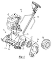
- Figure 1 is an exploded perspective view of a walk-behind reel mower constructed in accordance with the teachings of the present invention
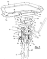
- Figure 2 is an exploded perspective view of an operator control assembly of the walk-behind greensmower of the present invention
- Figure 3 is a partial perspective view of the operator control assembly of the walk-behind greensmower of the present invention
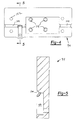
- Figure 4 is a plan view of a tilt plate of the present invention.
- Figure 5 is a cross-sectional view as taken along line 5-5 of Figure 4;
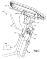
- Figure 6 is a partial perspective view of a tilt mechanism of the present invention.
- FIG. 7 is a perspective view depicting an alternative embodiment operator control assembly constructed in accordance with the teaching of the present invention.
- Mower 10 includes a cutting unit 12 and an operator control assembly 14.
- Cutting unit 12 includes a power source or engine 15 coupled to a frame 16.
- a traction roller 18 is rotatably coupled to frame 16 and drivingly connected to engine 15.
- a reel 20 includes a plurality of blades 22 rotatably mounted to frame 16.
- Reel 20 is selectively driven by engine 15.
- a transmission 24 includes a plurality of sprockets 25 selectively transferring rotational output torque of engine 15 to traction roller 18 and/or reel 20.
- Transmission 24 includes a clutch 26 positioned intermediate engine 15 and transmission 24.
- Clutch 26 is operable in an engaged mode and a disengaged mode for selectively transferring power from engine 15 to traction roller 18 and reel 20. Wheels 28 are coupled to traction roller 18 and are also selectively driven by engine 15 to provide motive force for translating walk-behind greensmower 10 along the ground. It should be appreciated that while the operator control assembly of the present invention is shown in conjunction with a walk-behind greensmower powered by an internal combustion engine, other devices are contemplated. For example, any walk-behind device such as a blower, string trimmer or mower may incorporate the operator control assembly of the present invention. Furthermore, these devices may utilize electric motors, hybrid power sources or the like.
- operator control assembly 14 includes a support arm 30, an actuation assembly 32, a tilt mechanism 34 and a handle assembly 36.
- Support arm 30 provides a substantially rigid structure for supporting actuation assembly 32 and tilt mechanism 34.
- Support arm 30 interconnects handle assembly 36 and frame 16 to allow an operator to control the direction of movement of mower 10.
- Support arm 30 includes a first end 37 and a second end 38.
- First end 37 includes a pair of bifurcated tubular legs 39 pivotally coupled to frame 16. The pivotal interconnection allows a user to rotate the entire operator control assembly about a pivot axis 40 to account for variation in operator stature.
- Second end 38 provides a rigid mount for tilt mechanism 34.
- a support bracket 42 is coupled to support arm 30 intermediate first end 37 and second end 38.
- Support bracket 42 provides mounting locations for a variety of components of actuation assembly 32.
- a guide sleeve 44, a pivot pin 45, and a cable bracket 46 are also coupled to support arm 30 to provide a mount for components of actuation assembly 32
- Actuation assembly 32 includes a control arm 48 selectively positionable in a neutral position (shown in Figure 2), a drive position and a brake position.
- Control arm 48 provides an operator a single interface for engaging and disengaging clutch 26 as well as for applying or releasing the brakes (not shown).
- Control arm 48 includes a substantially cylindrical first portion 50 and a substantially cylindrical second portion 52.
- a cam 54 is fixed to first portion 50.
- Cam 54 includes a lower lobe 56 and an upper lobe 58.
- First portion 50 is rotatably supported within guide sleeve 44.
- a cable link 60 is coupled to an end of control arm 48 such that guide sleeve 44 is trapped between cable link 60 and cam 54 to limit axial movement of control arm 48.
- a clutch cable 62 is coupled to first end 64 of cable link 60.
- a pair of brake cables 66 is pivotally coupled to a second end 68 of cable link 60.
- Cable link 60 also includes a paddle 70 for engagement with an electromagnet 72, as will be described in greater detail hereinafter.
- a pawl 74 is pivotally coupled to pivot pin 45. Pawl 74 is selectively positionable in an engaged position as shown in Figure 3, and a disengaged position where pawl 74 does not contact cam 54. Pawl 74 includes a head 78 selectively engageable with cam 54 and a finger 80 positioned distally from head 78. A yoke 82 is pivotally coupled to pawl 74 and is configured to mount one end of a control cable 84 thereto. A spring 85 partially surrounds control cable 84 and loads pawl 74 to bias head 78 into engagement with cam 54.
- a micro-switch 86 is mounted to support bracket 42 and is selectively actuated by finger 80 of pawl 74.
- Micro-switch 86 is normally open and in electrical communication with a rectifier 88 and electromagnet 72.
- rectifier 88 accepts an alternating current signal from engine 15 and converts the alternating current signal into a direct current input to micro-switch 86.
- the circuit is closed to supply a DC signal to electromagnet 72.
- Handle assembly 36 includes a handle 90, a bale 92, a tilt plate 94 and a throttle control 96.
- Bale 92 is pivotally coupled to handle 90 to provide an operator presence control.
- Bale 92 is rotatable from a disengaged position shown in Figure 3 to a rearward engaged position where bale 92 contacts handle 90.
- Bale 92 is a substantially closed loop wire-form having a substantially cylindrical base leg 98.
- a stop 100 is rigidly coupled to base leg 98 and inwardly protrudes therefrom. Stop 100 includes a detent 102 for receipt of the opposite end of control cable 84.
- Spring 85 provides a biasing force on control cable 84 such that bale 92 is biased to the disengaged position.
- tilt plate 94 includes a journal 104 to rotatably support base leg 98. Tilt plate 94 also includes a pocket 106 for receipt of stop 100. The articulation angle of bale 92 toward the disengaged position is limited by the size of pocket 106. Specifically, stop 100 contacts tilt plate 94 after it has rotated through the clearance provided by pocket 106.
- Handle 90 includes an integrally molded base 108.
- Base 108 includes a mounting surface 110, journals 112 and bosses 114. Journals 112 cooperate with journal 104 of tilt plate 94 to capture base leg 98 of bale 92 while providing rotational freedom to the bale.
- Threaded fasteners 116 extend through apertures 118 of tilt plate 94 to couple tilt mechanism 34 to base 108 of handle 90. Additional fasteners 120 extend through apertures 122 of tilt plate 94 to couple the tilt plate to base 108.
- Throttle control 96 is mounted to bosses 114 to provide a conveniently located adjustable throttle adjacent the operator's hands.
- tilt mechanism 34 includes an upper bracket 124 pivotally coupled to a lower bracket 126.
- a lever 128 is pivotally coupled to upper bracket 124 and is rotatable to selectively place tilt mechanism 34 in a locked or unlocked mode.
- a spring 130 biases lever 128 toward a first position corresponding to the locked mode.
- Upper bracket 124 is a substantially "C" shaped member having a base 132 and a pair of side walls 134.
- Base 132 includes a plurality of apertures 136 extending therethrough for receipt of fasteners 116.
- Lower bracket 126 is also a substantially "C" shaped member having a base 138 and a pair of side walls 140. Each of side walls 134 and 140 includes an aperture for receipt of a pin 142 to pivotally interconnect upper bracket 124 to lower bracket 126.
- Lever 128 includes a body 144, a tang 146 and a pair of vertical supports 148 downwardly extending from body 144. Tang 146 extends outwardly beyond the upper and lower brackets to provide a surface which may be easily grasped by an operator.
- a plurality of teeth 150 are positioned at an end of at least one of vertical supports 148.
- a pair of reinforcing plates 154 is coupled to an inner surface of side walls 140 of lower bracket 126.
- a plurality of teeth 156 are positioned on the distal end of at least one of reinforcing plates 154. Teeth 156 are normally positioned in meshing engagement with teeth 150 due to the biasing force supplied by spring 130. When the two sets of teeth are engaged, the angular position of handle 90 is fixed.
- lever 128 is rotated about an axis 158 to disengage teeth 150 from teeth 156. Once the teeth are disengaged, the operator may rotate handle 90 to a desired position. By providing this adjustment feature, operator fatigue and discomfort should be minimized.
- a shroud 160 ( Figure 2) is placed over upper bracket 124 and lever 128 to limit ingress of contaminants and operator appendages within the area defined between upper bracket 124 and lower bracket 126.
- engine 15 is started and an electrical AC signal is supplied to rectifier 88.
- Rectifier 88 converts the AC signal into a DC signal which is supplied to micro-switch 86.
- Micro-switch 86 is normally open and current is not supplied to electromagnet 72 at this time. If an operator wishes to drive traction roller 18 and/or reel assembly 20, bale 92 is rotated rearwardly to the engaged position. Rotation of bale 92 causes stop 100 to rotate and impart tension to control cable 84. Control cable 84 causes pawl 74 to rotate thereby disengaging head 78 from lower lobe 56 of cam 54. As pawl 74 is rotated, finger 80 closes micro-switch 86 to provide a DC signal to electromagnet 72.
- control arm 48 is rotated toward cutting unit 12.
- Paddle 70 engages an upper surface 162 of electromagnet 72 thereby limiting the maximum rotation of control arm 48.
- a coupling 164 pivotally interconnects electromagnet 72 and support bracket 42.
- a spring 166 positions electromagnet 72 in a substantially vertical orientation. However, spring 166 also allows electromagnet 72 to move via coupling 164 when paddle 70 comes into contact with surface 162 thereby providing optimum alignment between the paddle and the electromagnet.
- a tensioning force is imparted to clutch cable 62.
- Clutch 26 is shifted to its engaged mode where drive torque is supplied from engine 15 to traction roller 18 and reel assembly 20.
- control arm 48 is retained in a position to engage clutch 26.
- Clutch cable 62 is biasedly loaded in a direction to urge control arm 48 to the neutral position but the torque generated by electromagnet 72 and paddle 70 is greater than the torque provided by clutch cable 62. Therefore, the operator need not continue applying force to control arm 48 once clutch 26 is engaged.
- the operator presence control functions to discontinue the supply of power from engine 15 to traction roller 18 and reel assembly 20 if bale 92 is released.
- spring 85 urges pawl 74 to rotate.
- head 78 engages upper lobe 58 of cam 54 and finger 80 becomes spaced apart from micro-switch 86.
- Micro-switch 86 opens and discontinues supply of power to electromagnet 72.
- cable link 60, cam 54 and control arm 48 rotate away from cutting unit 12 toward the neutral position due to the return spring load provided by clutch cable 62.
- Control arm 48 tends to remain in the neutral position because at least one of brake cables 66 also includes a return spring counteracting the clutch cable return spring load.
- control arm 48 is rotated to the neutral position, head 78 of pawl 74 engaged lower lobe 56 of cam 54 to provide a lock-out feature.
- control arm 48 is locked-out from rotating toward cutting unit 12 by head 78. In this manner, traction roller 18 and reel assembly 20 may not be actuated without an operator present to maintain bale 92 in its engaged position.
- Braking may be accomplished by rotating control arm 48 away from cutting unit 12.
- bale 92 need not be rotated into the engaged position to actuate the brakes.
- cable link 60 imparts a tensile force to brake cables 66, thereby actuating the brakes.
- cable link 60 may continue to be rotated such that an attachment pin 168 of brake cables 66 is moved to an over-center position, thereby providing a parking brake function.
- the range of motion in the over-center direction is limited by paddle 70 contacting pivot pin 45.
- both brakes remain applied after the force to control arm 48 has been removed.
- the brakes may be released by simply rotating control arm 48 to the neutral position.
- Figure 7 depicts an alternate operator control assembly 200 including a first micro-switch 202, a second micro-switch 204, a relay 206 and an electromagnetic clutch 208.
- the micro-switches and electromagnetic clutch are used in lieu of the previously described clutch, control cable assembly and electromagnet.
- first micro-switch 202 is normally open and is closed upon movement of bale 92 to the engaged position. Once first micro-switch 202 is closed, current is supplied to relay 206.
- control arm 48 is rotated toward cutting unit 12, cable link 60 contacts second micro-switch 204 in a momentary fashion to latch relay 206.
- the latching of relay 206 causes current to flow to electromagnetic clutch 208 when first micro-switch 202 is closed, thereby placing electromagnetic clutch 208 in an engaged mode.
- Electromagnetic clutch 208 is maintained in the engaged mode as long as bale 92 is positioned in the engaged position and first micro-switch 202 is closed. If bale 92 is released to the disengaged position, first micro-switch 202 opens and discontinues the supply of current to electromagnetic clutch 208 thereby de-coupling engine 15 and traction roller 18.
Landscapes
- Life Sciences & Earth Sciences (AREA)
- Environmental Sciences (AREA)
- Harvester Elements (AREA)
Applications Claiming Priority (2)
| Application Number | Priority Date | Filing Date | Title |
|---|---|---|---|
| US364778 | 2003-02-11 | ||
| US10/364,778 US6904740B2 (en) | 2003-02-11 | 2003-02-11 | Articulating handle for a walk-behind mower |
Publications (2)
| Publication Number | Publication Date |
|---|---|
| EP1446996A2 true EP1446996A2 (fr) | 2004-08-18 |
| EP1446996A3 EP1446996A3 (fr) | 2004-12-29 |
Family
ID=32681696
Family Applications (1)
| Application Number | Title | Priority Date | Filing Date |
|---|---|---|---|
| EP03021641A Withdrawn EP1446996A3 (fr) | 2003-02-11 | 2003-09-26 | Poignée articulée pour faucheuse guidée à la main |
Country Status (10)
| Country | Link |
|---|---|
| US (2) | US6904740B2 (fr) |
| EP (1) | EP1446996A3 (fr) |
| JP (1) | JP2004242666A (fr) |
| KR (1) | KR20040073258A (fr) |
| CN (2) | CN1285251C (fr) |
| AU (1) | AU2003248298A1 (fr) |
| CA (1) | CA2441717A1 (fr) |
| MX (1) | MXPA03009146A (fr) |
| NZ (2) | NZ533947A (fr) |
| TW (1) | TWI239806B (fr) |
Cited By (1)
| Publication number | Priority date | Publication date | Assignee | Title |
|---|---|---|---|---|
| WO2010002298A1 (fr) * | 2008-06-30 | 2010-01-07 | Husqvarna Ab | Système de commande manuelle d'entraînement pour une tondeuse à gazon |
Families Citing this family (21)
| Publication number | Priority date | Publication date | Assignee | Title |
|---|---|---|---|---|
| JP4255957B2 (ja) * | 2006-04-27 | 2009-04-22 | 株式会社共栄社 | 歩行型芝刈機の運転操作装置 |
| JP4925723B2 (ja) * | 2006-05-24 | 2012-05-09 | 本田技研工業株式会社 | 芝刈機の駆動操作機構 |
| CN101147452B (zh) * | 2006-09-21 | 2011-09-07 | 苏州宝时得电动工具有限公司 | 割草机 |
| US20080128185A1 (en) * | 2006-12-05 | 2008-06-05 | Chih-Ching Hsieh | Tool Cart having electric motor powered wheels |
| US20080296107A1 (en) * | 2007-05-29 | 2008-12-04 | Porter Steven R | Parking brake actuator with spring force provided by flexible actuator cable |
| US7762050B1 (en) * | 2009-03-11 | 2010-07-27 | Honda Motor Co., Ltd. | Bail-free machine control devices and methods |
| CN102232332B (zh) * | 2010-04-21 | 2013-07-03 | 苏州宝时得电动工具有限公司 | 割草机 |
| CN102232331B (zh) * | 2010-04-21 | 2013-08-07 | 苏州宝时得电动工具有限公司 | 自驱割草机 |
| WO2011131031A1 (fr) * | 2010-04-21 | 2011-10-27 | 苏州宝时得电动工具有限公司 | Tondeuse à gazon et procédé de commande pour commander son fonctionnement à entraînement automatique |
| CN102771259A (zh) * | 2011-05-13 | 2012-11-14 | 苏州宝时得电动工具有限公司 | 自动割草机 |
| TWI469732B (zh) * | 2012-06-28 | 2015-01-21 | Wen Chang Wang | Shoulder backpack mower grip fit device |
| CN103270828B (zh) * | 2013-06-05 | 2016-05-18 | 中国农业大学 | 一种侧向移位株间除草机 |
| EP2839728B1 (fr) * | 2013-08-20 | 2018-10-24 | Robert Bosch GmbH | Véhicule, tel qu'un équipement de jardinage à roues |
| US9545054B2 (en) | 2014-10-22 | 2017-01-17 | Honda Motor Co., Ltd. | Mechanisms and related methods for drive by wire control systems in walk-behind working machines |
| CN106171253B (zh) * | 2015-05-05 | 2020-06-23 | 南京德朔实业有限公司 | 割草机 |
| US10414436B1 (en) | 2015-12-29 | 2019-09-17 | Hydro-Gear Limited Partnership | Control assembly for zero turn device |
| CN106612905A (zh) * | 2016-12-21 | 2017-05-10 | 张家港市金港镇宇鑫园家庭农场 | 一种割草机 |
| CN108464105B (zh) * | 2018-04-02 | 2021-04-13 | 倪为勇 | 一种切割速度可调式安全割草设备 |
| US11051450B2 (en) | 2018-11-09 | 2021-07-06 | The Toro Company | Walk reel mower with a telescopic handle assembly |
| DE102019202704A1 (de) * | 2019-02-28 | 2020-09-03 | Robert Bosch Gmbh | Bedienvorrichtung für eine Gartenbearbeitungsmaschine, Gartenbearbeitungsmaschine und Verfahren zu einem Betrieb der Gartenbearbeitungsmaschine |
| AU2024345601A1 (en) * | 2023-09-20 | 2026-02-12 | Nanjing Chervon Industry Co., Ltd. | Stand-on lawn mower |
Family Cites Families (33)
| Publication number | Priority date | Publication date | Assignee | Title |
|---|---|---|---|---|
| US854424A (en) * | 1904-08-22 | 1907-05-21 | Max Ketterer | Attachment for lawn-mowers. |
| US2965386A (en) * | 1956-11-16 | 1960-12-20 | Motor Wheel Corp | Lawn mower handle mounting structure |
| US3102022A (en) * | 1960-11-08 | 1963-08-27 | Monsanto Chemicals | Herbicidal method |
| US3581480A (en) | 1969-09-30 | 1971-06-01 | Black & Decker Mfg Co | Multiple-function receptacle and interconnecting plugs therefor |
| ZA706066B (en) * | 1970-04-08 | 1971-05-27 | Victa Ltd | A safety flap arrangement for discharge apertures in rotary lawnmower baseplates |
| US3946543A (en) | 1971-12-10 | 1976-03-30 | Templeton William E | Power mower with hydraulic drive |
| US3764156A (en) * | 1972-02-01 | 1973-10-09 | Arctic Ets | Mounting device for securing a handle to a lawn mower |
| DE2217351A1 (de) | 1972-04-11 | 1973-10-31 | Wolf Geraete Gmbh | Elektromotorisch angetriebener rasenmaeher |
| US4117651A (en) | 1976-07-12 | 1978-10-03 | Outboard Marine Corporation | Lawn mower with cutter blade interlock |
| US4322934A (en) | 1979-11-26 | 1982-04-06 | Fuso Keigokin Co., Ltd. | Lawn mower |
| US4354149A (en) | 1980-09-11 | 1982-10-12 | Armond Joseph A | Battery charge system |
| US4440277A (en) * | 1981-10-13 | 1984-04-03 | Claude W. Morris | Implement clutch and brake control |
| US4558558A (en) * | 1984-07-31 | 1985-12-17 | The Toro Company | Lawn mower traction control system |
| DE3500591A1 (de) | 1985-01-10 | 1986-07-10 | Bär Elektrowerke GmbH & Co KG, 5885 Schalksmühle | Elektrische schaltvorrichtung |
| US4835409A (en) | 1988-02-26 | 1989-05-30 | Black & Decker Inc. | Corded/cordless dual-mode power-operated device |
| US4854540A (en) | 1988-02-29 | 1989-08-08 | LTL Industries Ltd. | Vehicle battery mounting apparatus |
| JP2520161Y2 (ja) | 1988-06-20 | 1996-12-11 | 本田技研工業株式会社 | 草刈作業機の制御装置 |
| GB8908633D0 (en) | 1989-04-17 | 1989-06-01 | Electrolux Northern | Safety control device |
| US4995227A (en) | 1989-10-25 | 1991-02-26 | Foster Harry C | Power assisted reel type lawn mower |
| DE4137162A1 (de) | 1991-11-12 | 1993-05-13 | Wolf Dietrich Zinck | Rasenmaeher |
| DE69218251T2 (de) | 1992-01-03 | 1997-10-09 | Toro Co | Elektronische regelung von einem fahrzeug zur rasenbehandlung |
| EP0817352A2 (fr) | 1992-08-18 | 1998-01-07 | Black & Decker Inc. | Améliorations aux machines électriques à batterie |
| US5606851A (en) | 1993-09-22 | 1997-03-04 | Briggs & Stratton Corporation | Battery-powered lawn cutting system |
| US5442901A (en) | 1994-07-22 | 1995-08-22 | Ryobi North America | Self-propelled mower |
| US5509258A (en) | 1995-01-30 | 1996-04-23 | Deere & Company | Operator presence control for reel mower |
| GB2303719B (en) | 1995-07-26 | 2000-01-26 | Black & Decker Inc | An energy management system for a cordless vegetation cutter |
| RU2201062C2 (ru) | 1995-08-17 | 2003-03-27 | Томас Б. Бурч | Устройство и способ для подрезания и обработки растений |
| WO1997028681A2 (fr) | 1996-02-09 | 1997-08-14 | The Toro Company | Tondeuse a gazon electrique |
| US6170241B1 (en) | 1996-04-26 | 2001-01-09 | Tecumseh Products Company | Microprocessor controlled motor controller with current limiting protection |
| US5727372A (en) | 1996-05-30 | 1998-03-17 | The Toro Company | On-board charging system for electric lawn mower |
| US6102022A (en) * | 1997-01-07 | 2000-08-15 | Crafco, Incorporated | Pavement cutting machine |
| US5909064A (en) | 1997-07-16 | 1999-06-01 | Siemens Electromechanical Components, Inc. | Time delay relay circuit |
| US6047786A (en) | 1997-12-11 | 2000-04-11 | Vectrix Corporation | Electric vehicle and frame therefor |
-
2003
- 2003-02-11 US US10/364,778 patent/US6904740B2/en not_active Expired - Fee Related
- 2003-09-19 CA CA002441717A patent/CA2441717A1/fr not_active Abandoned
- 2003-09-23 AU AU2003248298A patent/AU2003248298A1/en not_active Abandoned
- 2003-09-24 NZ NZ533947A patent/NZ533947A/en unknown
- 2003-09-24 NZ NZ528430A patent/NZ528430A/en unknown
- 2003-09-26 EP EP03021641A patent/EP1446996A3/fr not_active Withdrawn
- 2003-09-26 TW TW092126728A patent/TWI239806B/zh not_active IP Right Cessation
- 2003-09-26 JP JP2003335818A patent/JP2004242666A/ja active Pending
- 2003-09-26 KR KR1020030067034A patent/KR20040073258A/ko not_active Abandoned
- 2003-09-28 CN CNB03154438XA patent/CN1285251C/zh not_active Expired - Fee Related
- 2003-09-28 CN CNA2006100073309A patent/CN1817081A/zh active Pending
- 2003-10-07 MX MXPA03009146A patent/MXPA03009146A/es unknown
-
2004
- 2004-10-28 US US10/976,254 patent/US20050055992A1/en not_active Abandoned
Cited By (1)
| Publication number | Priority date | Publication date | Assignee | Title |
|---|---|---|---|---|
| WO2010002298A1 (fr) * | 2008-06-30 | 2010-01-07 | Husqvarna Ab | Système de commande manuelle d'entraînement pour une tondeuse à gazon |
Also Published As
| Publication number | Publication date |
|---|---|
| US20050055992A1 (en) | 2005-03-17 |
| CN1520706A (zh) | 2004-08-18 |
| US6904740B2 (en) | 2005-06-14 |
| CN1817081A (zh) | 2006-08-16 |
| CN1285251C (zh) | 2006-11-22 |
| TW200414869A (en) | 2004-08-16 |
| KR20040073258A (ko) | 2004-08-19 |
| AU2003248298A1 (en) | 2004-08-26 |
| TWI239806B (en) | 2005-09-21 |
| NZ528430A (en) | 2004-08-27 |
| EP1446996A3 (fr) | 2004-12-29 |
| NZ533947A (en) | 2005-03-24 |
| MXPA03009146A (es) | 2004-08-13 |
| CA2441717A1 (fr) | 2004-08-11 |
| JP2004242666A (ja) | 2004-09-02 |
| US20040154275A1 (en) | 2004-08-12 |
Similar Documents
| Publication | Publication Date | Title |
|---|---|---|
| US6904740B2 (en) | Articulating handle for a walk-behind mower | |
| US4573307A (en) | Lawn mower dead man control | |
| CA1287952C (fr) | Aspirateur vertical autopopulse a transmission a distance et mecanisme de calage absolu | |
| AU2017332358B2 (en) | Control assembly for a walk-behind mower | |
| CN101828470B (zh) | 无拉手的机器控制装置和方法 | |
| CA1245866A (fr) | Manette d'homme mort pour tondeuse de pelouse | |
| KR101122420B1 (ko) | 예초기 | |
| AU2009338110B2 (en) | Door prop in a lawn mower | |
| US7240756B2 (en) | Method of operator presence control on walk behind powered equipment | |
| US6568162B2 (en) | Control system for a cutting assembly of a lawn tractor | |
| CA2345601C (fr) | Dispositif de blocage de biellette d'alimentation a poignee | |
| US6779323B2 (en) | Elongate barrier system for use with lawn mower decks | |
| US7003935B2 (en) | Mower with integrated occupant presence and independent drive and brake lockout | |
| EP1457103A1 (fr) | Papillon | |
| JP2002303229A (ja) | 作業機の始動安全装置、それを備えた作業機及び作業機の始動時の安全を図る方法 | |
| HK1065439A (en) | Articulating handle for a walk-behind mower | |
| CA1251047A (fr) | Commande d'homme mort sur tondeuse de pelouse | |
| US8695314B2 (en) | Two-way action cable control assemblies, systems and methods | |
| JPH08226505A (ja) | Ptoブレーキ構造 | |
| WO2016207833A1 (fr) | Commande d'entraînement, outil électrique extérieur poussé |
Legal Events
| Date | Code | Title | Description |
|---|---|---|---|
| PUAI | Public reference made under article 153(3) epc to a published international application that has entered the european phase |
Free format text: ORIGINAL CODE: 0009012 |
|
| 17P | Request for examination filed |
Effective date: 20031105 |
|
| AK | Designated contracting states |
Kind code of ref document: A2 Designated state(s): AT BE BG CH CY CZ DE DK EE ES FI FR GB GR HU IE IT LI LU MC NL PT RO SE SI SK TR |
|
| AX | Request for extension of the european patent |
Extension state: AL LT LV MK |
|
| PUAL | Search report despatched |
Free format text: ORIGINAL CODE: 0009013 |
|
| AK | Designated contracting states |
Kind code of ref document: A3 Designated state(s): AT BE BG CH CY CZ DE DK EE ES FI FR GB GR HU IE IT LI LU MC NL PT RO SE SI SK TR |
|
| AX | Request for extension of the european patent |
Extension state: AL LT LV MK |
|
| AKX | Designation fees paid |
Designated state(s): AT BE BG CH CY CZ DE DK EE ES FI FR GB GR HU IE IT LI LU MC NL PT RO SE SI SK TR |
|
| STAA | Information on the status of an ep patent application or granted ep patent |
Free format text: STATUS: THE APPLICATION IS DEEMED TO BE WITHDRAWN |
|
| 18D | Application deemed to be withdrawn |
Effective date: 20060808 |