EP1447555A2 - Füllstandsgeber für einen Flüssigkraftstofftank, insbesondere für ein System zur Zufuhr von LPG zu einer Brennkraftmaschine - Google Patents
Füllstandsgeber für einen Flüssigkraftstofftank, insbesondere für ein System zur Zufuhr von LPG zu einer Brennkraftmaschine Download PDFInfo
- Publication number
- EP1447555A2 EP1447555A2 EP04001785A EP04001785A EP1447555A2 EP 1447555 A2 EP1447555 A2 EP 1447555A2 EP 04001785 A EP04001785 A EP 04001785A EP 04001785 A EP04001785 A EP 04001785A EP 1447555 A2 EP1447555 A2 EP 1447555A2
- Authority
- EP
- European Patent Office
- Prior art keywords
- level
- tank
- floating member
- sensor device
- lpg
- Prior art date
- Legal status (The legal status is an assumption and is not a legal conclusion. Google has not performed a legal analysis and makes no representation as to the accuracy of the status listed.)
- Withdrawn
Links
Images
Classifications
-
- F—MECHANICAL ENGINEERING; LIGHTING; HEATING; WEAPONS; BLASTING
- F17—STORING OR DISTRIBUTING GASES OR LIQUIDS
- F17C—VESSELS FOR CONTAINING OR STORING COMPRESSED, LIQUEFIED OR SOLIDIFIED GASES; FIXED-CAPACITY GAS-HOLDERS; FILLING VESSELS WITH, OR DISCHARGING FROM VESSELS, COMPRESSED, LIQUEFIED, OR SOLIDIFIED GASES
- F17C13/00—Details of vessels or of the filling or discharging of vessels
- F17C13/02—Special adaptations of indicating, measuring, or monitoring equipment
- F17C13/021—Special adaptations of indicating, measuring, or monitoring equipment having the height as the parameter
-
- F—MECHANICAL ENGINEERING; LIGHTING; HEATING; WEAPONS; BLASTING
- F02—COMBUSTION ENGINES; HOT-GAS OR COMBUSTION-PRODUCT ENGINE PLANTS
- F02D—CONTROLLING COMBUSTION ENGINES
- F02D19/00—Controlling engines characterised by their use of non-liquid fuels, pluralities of fuels, or non-fuel substances added to the combustible mixtures
- F02D19/02—Controlling engines characterised by their use of non-liquid fuels, pluralities of fuels, or non-fuel substances added to the combustible mixtures peculiar to engines working with gaseous fuels
- F02D19/026—Measuring or estimating parameters related to the fuel supply system
- F02D19/027—Determining the fuel pressure, temperature or volume flow, the fuel tank fill level or a valve position
-
- F—MECHANICAL ENGINEERING; LIGHTING; HEATING; WEAPONS; BLASTING
- F02—COMBUSTION ENGINES; HOT-GAS OR COMBUSTION-PRODUCT ENGINE PLANTS
- F02M—SUPPLYING COMBUSTION ENGINES IN GENERAL WITH COMBUSTIBLE MIXTURES OR CONSTITUENTS THEREOF
- F02M21/00—Apparatus for supplying engines with non-liquid fuels, e.g. gaseous fuels stored in liquid form
- F02M21/02—Apparatus for supplying engines with non-liquid fuels, e.g. gaseous fuels stored in liquid form for gaseous fuels
- F02M21/0203—Apparatus for supplying engines with non-liquid fuels, e.g. gaseous fuels stored in liquid form for gaseous fuels characterised by the type of gaseous fuel
- F02M21/0209—Hydrocarbon fuels, e.g. methane or acetylene
- F02M21/0212—Hydrocarbon fuels, e.g. methane or acetylene comprising at least 3 C-Atoms, e.g. liquefied petroleum gas [LPG], propane or butane
-
- F—MECHANICAL ENGINEERING; LIGHTING; HEATING; WEAPONS; BLASTING
- F02—COMBUSTION ENGINES; HOT-GAS OR COMBUSTION-PRODUCT ENGINE PLANTS
- F02M—SUPPLYING COMBUSTION ENGINES IN GENERAL WITH COMBUSTIBLE MIXTURES OR CONSTITUENTS THEREOF
- F02M21/00—Apparatus for supplying engines with non-liquid fuels, e.g. gaseous fuels stored in liquid form
- F02M21/02—Apparatus for supplying engines with non-liquid fuels, e.g. gaseous fuels stored in liquid form for gaseous fuels
- F02M21/0218—Details on the gaseous fuel supply system, e.g. tanks, valves, pipes, pumps, rails, injectors or mixers
- F02M21/0221—Fuel storage reservoirs, e.g. cryogenic tanks
-
- F—MECHANICAL ENGINEERING; LIGHTING; HEATING; WEAPONS; BLASTING
- F02—COMBUSTION ENGINES; HOT-GAS OR COMBUSTION-PRODUCT ENGINE PLANTS
- F02M—SUPPLYING COMBUSTION ENGINES IN GENERAL WITH COMBUSTIBLE MIXTURES OR CONSTITUENTS THEREOF
- F02M21/00—Apparatus for supplying engines with non-liquid fuels, e.g. gaseous fuels stored in liquid form
- F02M21/02—Apparatus for supplying engines with non-liquid fuels, e.g. gaseous fuels stored in liquid form for gaseous fuels
- F02M21/0218—Details on the gaseous fuel supply system, e.g. tanks, valves, pipes, pumps, rails, injectors or mixers
- F02M21/0245—High pressure fuel supply systems; Rails; Pumps; Arrangement of valves
-
- F—MECHANICAL ENGINEERING; LIGHTING; HEATING; WEAPONS; BLASTING
- F02—COMBUSTION ENGINES; HOT-GAS OR COMBUSTION-PRODUCT ENGINE PLANTS
- F02M—SUPPLYING COMBUSTION ENGINES IN GENERAL WITH COMBUSTIBLE MIXTURES OR CONSTITUENTS THEREOF
- F02M37/00—Apparatus or systems for feeding liquid fuel from storage containers to carburettors or fuel-injection apparatus; Arrangements for purifying liquid fuel specially adapted for, or arranged on, internal-combustion engines
- F02M37/04—Feeding by means of driven pumps
- F02M37/08—Feeding by means of driven pumps electrically driven
- F02M37/10—Feeding by means of driven pumps electrically driven submerged in fuel, e.g. in reservoir
- F02M37/103—Mounting pumps on fuel tanks
-
- G—PHYSICS
- G01—MEASURING; TESTING
- G01F—MEASURING VOLUME, VOLUME FLOW, MASS FLOW OR LIQUID LEVEL; METERING BY VOLUME
- G01F23/00—Indicating or measuring liquid level or level of fluent solid material, e.g. indicating in terms of volume or indicating by means of an alarm
- G01F23/30—Indicating or measuring liquid level or level of fluent solid material, e.g. indicating in terms of volume or indicating by means of an alarm by floats
- G01F23/64—Indicating or measuring liquid level or level of fluent solid material, e.g. indicating in terms of volume or indicating by means of an alarm by floats of the free float type without mechanical transmission elements
- G01F23/72—Indicating or measuring liquid level or level of fluent solid material, e.g. indicating in terms of volume or indicating by means of an alarm by floats of the free float type without mechanical transmission elements using magnetically actuated indicating means
- G01F23/74—Indicating or measuring liquid level or level of fluent solid material, e.g. indicating in terms of volume or indicating by means of an alarm by floats of the free float type without mechanical transmission elements using magnetically actuated indicating means for sensing changes in level only at discrete points
-
- F—MECHANICAL ENGINEERING; LIGHTING; HEATING; WEAPONS; BLASTING
- F17—STORING OR DISTRIBUTING GASES OR LIQUIDS
- F17C—VESSELS FOR CONTAINING OR STORING COMPRESSED, LIQUEFIED OR SOLIDIFIED GASES; FIXED-CAPACITY GAS-HOLDERS; FILLING VESSELS WITH, OR DISCHARGING FROM VESSELS, COMPRESSED, LIQUEFIED, OR SOLIDIFIED GASES
- F17C2201/00—Vessel construction, in particular geometry, arrangement or size
- F17C2201/01—Shape
- F17C2201/0104—Shape cylindrical
-
- F—MECHANICAL ENGINEERING; LIGHTING; HEATING; WEAPONS; BLASTING
- F17—STORING OR DISTRIBUTING GASES OR LIQUIDS
- F17C—VESSELS FOR CONTAINING OR STORING COMPRESSED, LIQUEFIED OR SOLIDIFIED GASES; FIXED-CAPACITY GAS-HOLDERS; FILLING VESSELS WITH, OR DISCHARGING FROM VESSELS, COMPRESSED, LIQUEFIED, OR SOLIDIFIED GASES
- F17C2201/00—Vessel construction, in particular geometry, arrangement or size
- F17C2201/03—Orientation
- F17C2201/035—Orientation with substantially horizontal main axis
-
- F—MECHANICAL ENGINEERING; LIGHTING; HEATING; WEAPONS; BLASTING
- F17—STORING OR DISTRIBUTING GASES OR LIQUIDS
- F17C—VESSELS FOR CONTAINING OR STORING COMPRESSED, LIQUEFIED OR SOLIDIFIED GASES; FIXED-CAPACITY GAS-HOLDERS; FILLING VESSELS WITH, OR DISCHARGING FROM VESSELS, COMPRESSED, LIQUEFIED, OR SOLIDIFIED GASES
- F17C2201/00—Vessel construction, in particular geometry, arrangement or size
- F17C2201/05—Size
- F17C2201/056—Small (<1 m3)
-
- F—MECHANICAL ENGINEERING; LIGHTING; HEATING; WEAPONS; BLASTING
- F17—STORING OR DISTRIBUTING GASES OR LIQUIDS
- F17C—VESSELS FOR CONTAINING OR STORING COMPRESSED, LIQUEFIED OR SOLIDIFIED GASES; FIXED-CAPACITY GAS-HOLDERS; FILLING VESSELS WITH, OR DISCHARGING FROM VESSELS, COMPRESSED, LIQUEFIED, OR SOLIDIFIED GASES
- F17C2205/00—Vessel construction, in particular mounting arrangements, attachments or identifications means
- F17C2205/03—Fluid connections, filters, valves, closure means or other attachments
- F17C2205/0302—Fittings, valves, filters, or components in connection with the gas storage device
- F17C2205/0323—Valves
- F17C2205/0326—Valves electrically actuated
-
- F—MECHANICAL ENGINEERING; LIGHTING; HEATING; WEAPONS; BLASTING
- F17—STORING OR DISTRIBUTING GASES OR LIQUIDS
- F17C—VESSELS FOR CONTAINING OR STORING COMPRESSED, LIQUEFIED OR SOLIDIFIED GASES; FIXED-CAPACITY GAS-HOLDERS; FILLING VESSELS WITH, OR DISCHARGING FROM VESSELS, COMPRESSED, LIQUEFIED, OR SOLIDIFIED GASES
- F17C2221/00—Handled fluid, in particular type of fluid
- F17C2221/03—Mixtures
- F17C2221/032—Hydrocarbons
- F17C2221/035—Propane butane, e.g. LPG, GPL
-
- F—MECHANICAL ENGINEERING; LIGHTING; HEATING; WEAPONS; BLASTING
- F17—STORING OR DISTRIBUTING GASES OR LIQUIDS
- F17C—VESSELS FOR CONTAINING OR STORING COMPRESSED, LIQUEFIED OR SOLIDIFIED GASES; FIXED-CAPACITY GAS-HOLDERS; FILLING VESSELS WITH, OR DISCHARGING FROM VESSELS, COMPRESSED, LIQUEFIED, OR SOLIDIFIED GASES
- F17C2223/00—Handled fluid before transfer, i.e. state of fluid when stored in the vessel or before transfer from the vessel
- F17C2223/01—Handled fluid before transfer, i.e. state of fluid when stored in the vessel or before transfer from the vessel characterised by the phase
- F17C2223/0146—Two-phase
- F17C2223/0153—Liquefied gas, e.g. LPG, GPL
-
- F—MECHANICAL ENGINEERING; LIGHTING; HEATING; WEAPONS; BLASTING
- F17—STORING OR DISTRIBUTING GASES OR LIQUIDS
- F17C—VESSELS FOR CONTAINING OR STORING COMPRESSED, LIQUEFIED OR SOLIDIFIED GASES; FIXED-CAPACITY GAS-HOLDERS; FILLING VESSELS WITH, OR DISCHARGING FROM VESSELS, COMPRESSED, LIQUEFIED, OR SOLIDIFIED GASES
- F17C2223/00—Handled fluid before transfer, i.e. state of fluid when stored in the vessel or before transfer from the vessel
- F17C2223/03—Handled fluid before transfer, i.e. state of fluid when stored in the vessel or before transfer from the vessel characterised by the pressure level
- F17C2223/033—Small pressure, e.g. for liquefied gas
-
- F—MECHANICAL ENGINEERING; LIGHTING; HEATING; WEAPONS; BLASTING
- F17—STORING OR DISTRIBUTING GASES OR LIQUIDS
- F17C—VESSELS FOR CONTAINING OR STORING COMPRESSED, LIQUEFIED OR SOLIDIFIED GASES; FIXED-CAPACITY GAS-HOLDERS; FILLING VESSELS WITH, OR DISCHARGING FROM VESSELS, COMPRESSED, LIQUEFIED, OR SOLIDIFIED GASES
- F17C2227/00—Transfer of fluids, i.e. method or means for transferring the fluid; Heat exchange with the fluid
- F17C2227/01—Propulsion of the fluid
- F17C2227/0128—Propulsion of the fluid with pumps or compressors
- F17C2227/0135—Pumps
-
- F—MECHANICAL ENGINEERING; LIGHTING; HEATING; WEAPONS; BLASTING
- F17—STORING OR DISTRIBUTING GASES OR LIQUIDS
- F17C—VESSELS FOR CONTAINING OR STORING COMPRESSED, LIQUEFIED OR SOLIDIFIED GASES; FIXED-CAPACITY GAS-HOLDERS; FILLING VESSELS WITH, OR DISCHARGING FROM VESSELS, COMPRESSED, LIQUEFIED, OR SOLIDIFIED GASES
- F17C2227/00—Transfer of fluids, i.e. method or means for transferring the fluid; Heat exchange with the fluid
- F17C2227/01—Propulsion of the fluid
- F17C2227/0128—Propulsion of the fluid with pumps or compressors
- F17C2227/0171—Arrangement
- F17C2227/0178—Arrangement in the vessel
-
- F—MECHANICAL ENGINEERING; LIGHTING; HEATING; WEAPONS; BLASTING
- F17—STORING OR DISTRIBUTING GASES OR LIQUIDS
- F17C—VESSELS FOR CONTAINING OR STORING COMPRESSED, LIQUEFIED OR SOLIDIFIED GASES; FIXED-CAPACITY GAS-HOLDERS; FILLING VESSELS WITH, OR DISCHARGING FROM VESSELS, COMPRESSED, LIQUEFIED, OR SOLIDIFIED GASES
- F17C2250/00—Accessories; Control means; Indicating, measuring or monitoring of parameters
- F17C2250/04—Indicating or measuring of parameters as input values
- F17C2250/0404—Parameters indicated or measured
- F17C2250/0408—Level of content in the vessel
- F17C2250/0413—Level of content in the vessel with floats
-
- F—MECHANICAL ENGINEERING; LIGHTING; HEATING; WEAPONS; BLASTING
- F17—STORING OR DISTRIBUTING GASES OR LIQUIDS
- F17C—VESSELS FOR CONTAINING OR STORING COMPRESSED, LIQUEFIED OR SOLIDIFIED GASES; FIXED-CAPACITY GAS-HOLDERS; FILLING VESSELS WITH, OR DISCHARGING FROM VESSELS, COMPRESSED, LIQUEFIED, OR SOLIDIFIED GASES
- F17C2265/00—Effects achieved by gas storage or gas handling
- F17C2265/06—Fluid distribution
- F17C2265/066—Fluid distribution for feeding engines for propulsion
-
- F—MECHANICAL ENGINEERING; LIGHTING; HEATING; WEAPONS; BLASTING
- F17—STORING OR DISTRIBUTING GASES OR LIQUIDS
- F17C—VESSELS FOR CONTAINING OR STORING COMPRESSED, LIQUEFIED OR SOLIDIFIED GASES; FIXED-CAPACITY GAS-HOLDERS; FILLING VESSELS WITH, OR DISCHARGING FROM VESSELS, COMPRESSED, LIQUEFIED, OR SOLIDIFIED GASES
- F17C2270/00—Applications
- F17C2270/01—Applications for fluid transport or storage
- F17C2270/0165—Applications for fluid transport or storage on the road
- F17C2270/0168—Applications for fluid transport or storage on the road by vehicles
-
- Y—GENERAL TAGGING OF NEW TECHNOLOGICAL DEVELOPMENTS; GENERAL TAGGING OF CROSS-SECTIONAL TECHNOLOGIES SPANNING OVER SEVERAL SECTIONS OF THE IPC; TECHNICAL SUBJECTS COVERED BY FORMER USPC CROSS-REFERENCE ART COLLECTIONS [XRACs] AND DIGESTS
- Y02—TECHNOLOGIES OR APPLICATIONS FOR MITIGATION OR ADAPTATION AGAINST CLIMATE CHANGE
- Y02T—CLIMATE CHANGE MITIGATION TECHNOLOGIES RELATED TO TRANSPORTATION
- Y02T10/00—Road transport of goods or passengers
- Y02T10/10—Internal combustion engine [ICE] based vehicles
- Y02T10/30—Use of alternative fuels, e.g. biofuels
Definitions
- the present invention relates to level-sensor devices for liquid-fuel tanks, particularly for systems of LPG supply to internal-combustion engines of motor vehicles.
- the invention relates to level-sensor devices of the type referred to above, in which there is provided a floating member which can move vertically within the tank according to the variations of level of the fuel in the tank, and transducer means that are sensitive to the movement of the float for issuing an electrical signal that indicates the position of the float in the tank.
- the transducer means consist of a potentiometer, which is sensitive to the position of the aforesaid oscillating arm.
- a device of this type is, for example, illustrated in the European patent No. EP 0 922 851 B1 and in the corresponding US patent No. US 6 050 237 in the name of the present applicant.
- the subject of the present invention is a level-sensor device for a liquid-fuel tank, particularly for a system of LPG supply to an internal-combustion engine, having all the characteristics that have been mentioned at the beginning of the present description and being further characterized in that the floating member has a body vertically slidably guided in a within the tank, in that the aforesaid transducer means comprise a vertically aligned series of electrical magnetic-actuation switches of a reed-relay type, arranged adjacent to the float, and in that the body of the float comprises magnetic means designed to activate selectively one or more of the aforesaid magnetic-actuation switches according to the position of the float with respect to the aforesaid vertical series of electrical magnetic-actuation switches.
- the body of the float can be guided vertically within the tank without any sliding contact subject to friction.
- the body of the float has an annular conformation and is mounted with play on a central column consisting of a tubular element made of non-magnetic material containing within it the series of electrical magnetic-actuation switches.
- the floating assembly of the float on said column guides the float, forcing it to move in a vertical direction, and on the other hand, eliminates the friction present in the known solutions.
- the float is able to "sense” even minimal variations of level within the tank and is, in particular, able to give rise to a reliable warning when the level drops below a minimum threshold value corresponding to the activation of the "reserve” warning light on the instrument dashboard of the motor vehicle.
- the float has an annular body
- said body has a cylindrical conformation with a diameter/height ratio that is optimized in order to obtain the maximum displacement possible of liquid for a small variation in height.
- the assembly consisting of the column containing the series of reed relays with the annular float mounted thereon is enclosed within a cylindrical container having in the bottom part of its wall one or more openings for communication, via which the internal capacity of said container communicates with the remaining space within the tank. Thanks to said solution, the liquid on which the floating member floats is less subject to shaking deriving from the movements of the motor vehicle on which the tank is installed.
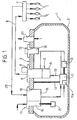
- the number 1 designates as a whole an LPG fuel tank built according to the known art, for supplying the LPG to a plurality of injectors I associated to the various cylinders of an internal-combustion engine of a motor vehicle.
- the tank 1 has a hollow structure 2 made so as to guarantee tightness at the working pressures expected for a system of the type in question.
- the hollow structure 2 has a top opening closed by a service flange 3 carrying the various elements for fitting and connection of the tank to the supply system.
- the tank 1 has a first through opening 4, through which there is installed the structure of an assembly 5 connected to a line 6 for delivery of the LPG to a distribution manifold or rail 7, which distributes the LPG between the various injectors I.
- the assembly 5 includes a shut-off solenoid valve 8 designed to close, interrupting communication of the tank with the outside environment in pre-determined emergency conditions, as well as a flow-limiting valve 9.
- the assembly 5 receives the LPG through the line 10 from the pump 11, which is controlled by an electric motor 11a, the structure of which is connected, by means of a connection element 12, to the service flange 3.
- the installation of the pump 11 can in any case be made in any other known way.
- Also connected to the structure of the pump 11 is the structure of a sensor device 13 for sensing the level of LPG.
- the electrical supply of the solenoid valve 8, of the pump 11, and of the sensor 13 is guaranteed by an electrical connector 14, which is mounted through a through opening 15 of the service flange 3.
- the latter moreover has a further through opening 16, within which there is installed an assembly 17 including two valves 18, 19.
- the valve 18 is a return valve, which is connected to a line 20 for the flow, within the tank, of the LPG supplied in excess to the rail 7.
- the valve 19 is the valve used for filling the tank and is associated to a further level-sensor 21.
- Also associated to the flange 3 is a safety valve 22, which prevents the pressure within the tank from exceeding a pre-determined threshold value.
- Figure 1 shows a traditional embodiment of a tank, in which the flange 3 has through holes traversed by the various components described above.
- the tank could moreover also have the innovative structure that has formed the subject of the preceding Italian patent application No. T02001A000360 in the name of the present applicant, in which at least some of the aforesaid components are fixed to the bottom surface of the plate, without passing through it.
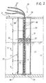
- a level-sensor device for example of the type illustrated in Figure 2.
- the sensor device 13 illustrated in Figure 1 is completely eliminated, and the level-sensor device indicated as a whole by the reference number 30 in Figure 2 is used.
- This has a structure completely independent both of that of the engine 11 illustrated in Figure 1 and of that of any other component present within the tank.
- the level-sensor device has a floating member 31 with an annular cylindrical body, in which there are embedded one or more permanent magnets 32.
- the case illustrated shows two magnets 32 arranged at 180° with respect to one another, but it would obviously be possible to provide, for example, three magnets arranged at 120° with respect to one another or any other number of permanent magnets arranged at angular distances apart from one another.
- the annular body 31 of the float is mounted in a slidable way, with play, on a vertical guide column 33 consisting of a tubular element made of non-magnetic material, the opposite ends of which are fixed centrally to a top plate 34 and to a bottom plate 35, which are fixed in any known way to the structure of the tank 2.
- a vertical guide column 33 consisting of a tubular element made of non-magnetic material, the opposite ends of which are fixed centrally to a top plate 34 and to a bottom plate 35, which are fixed in any known way to the structure of the tank 2.
- an aligned series of reed relays 36 that are connected to one another in a circuit, the ends of which are connected to conductors 37 coming out of the top end of the tubular element 33 and out of the top plate 34, for connection to an electronic control unit (not illustrated).
- the aligned arrangement of reed relays enables an electrical signal indicating the position of the float 31 along the vertical column 33 to be sent to the conductors 37.
- the permanent magnets 32 carried by the float 31 activate selectively one or more reed relays 36 according to the position of the float with respect to the column 33. The electrical signal at output from the device thus depends upon the position of the float.
- the assembly consisting of the supporting column 33 with the float 31 mounted thereon is enclosed within a cylindrical container 37, for example made of plastic material, which has holes 38, 39, of which at least one 38 is in its bottom part for communication of the internal cavity of the container 37 with the remaining space within the tank 2.
- a cylindrical container 37 for example made of plastic material, which has holes 38, 39, of which at least one 38 is in its bottom part for communication of the internal cavity of the container 37 with the remaining space within the tank 2.
- the liquid within the container 37 is less sensitive to the shaking resulting from the movements of the motor vehicle on which the tank is installed.
- the reed relays 36 are distributed with a different pitch in different portions of the length of the supporting column 33. More precisely, in the end portions indicated by A and C in Figure 2, the reed relays are arranged with a relatively small pitch, for example 5 mm apart, so as to enable a finer measurement when the LPG in the tank is reaching a minimum threshold value or when the level is reaching a maximum value, during refuelling of the vehicle. In the intermediate portion, designated by B, of the supporting column 33, the reed relays are instead arranged with a larger pitch, for example 10 mm.
- the supporting column has an overall height of approximately 200 mm and includes a distribution of approximately twenty, for example eighteen, reed relays.
- the annular body of the float 31 has an external diameter of 48 mm, a height of 18 mm and a diameter, of its internal opening of 13 mm.
- said dimensions can be amply varied. It is, however, desirable that the ratio external diameter/height of the float is optimized in order to obtain the maximum displacement of liquid for the minimum height, for example at least greater than 1 and preferably less than 2.
- the conformation and arrangement of the floating member could also be different from the one illustrated by way of example.
- the conformation and the arrangement of the structure that guides the vertical movement of the float could be completely different. The same applies to the structure carrying the series of reed relays.
Landscapes
- Engineering & Computer Science (AREA)
- Chemical & Material Sciences (AREA)
- Mechanical Engineering (AREA)
- General Engineering & Computer Science (AREA)
- Combustion & Propulsion (AREA)
- General Chemical & Material Sciences (AREA)
- Chemical Kinetics & Catalysis (AREA)
- Oil, Petroleum & Natural Gas (AREA)
- Physics & Mathematics (AREA)
- Fluid Mechanics (AREA)
- General Physics & Mathematics (AREA)
- Level Indicators Using A Float (AREA)
- Filling Or Discharging Of Gas Storage Vessels (AREA)
- Cooling, Air Intake And Gas Exhaust, And Fuel Tank Arrangements In Propulsion Units (AREA)
Applications Claiming Priority (2)
| Application Number | Priority Date | Filing Date | Title |
|---|---|---|---|
| IT000097A ITTO20030097A1 (it) | 2003-02-11 | 2003-02-11 | Dispositivo sensore di livello per un serbatoio di |
| ITTO20030097 | 2003-02-11 |
Publications (2)
| Publication Number | Publication Date |
|---|---|
| EP1447555A2 true EP1447555A2 (de) | 2004-08-18 |
| EP1447555A3 EP1447555A3 (de) | 2006-05-17 |
Family
ID=32676902
Family Applications (1)
| Application Number | Title | Priority Date | Filing Date |
|---|---|---|---|
| EP04001785A Withdrawn EP1447555A3 (de) | 2003-02-11 | 2004-01-28 | Füllstandsgeber für einen Flüssigkraftstofftank, insbesondere für ein System zur Zufuhr von LPG zu einer Brennkraftmaschine |
Country Status (5)
| Country | Link |
|---|---|
| US (1) | US6915692B2 (de) |
| EP (1) | EP1447555A3 (de) |
| AU (1) | AU2004200408B2 (de) |
| CA (1) | CA2456712A1 (de) |
| IT (1) | ITTO20030097A1 (de) |
Cited By (9)
| Publication number | Priority date | Publication date | Assignee | Title |
|---|---|---|---|---|
| DE202006001950U1 (de) * | 2006-02-06 | 2007-06-06 | Hengst Gmbh & Co.Kg | Fluidfilter, mit geschütztem Flüssigkeitssensor |
| US20070169759A1 (en) * | 2006-01-26 | 2007-07-26 | Frenette Henry E | Vapor fuel combustion system |
| WO2009063506A3 (en) * | 2007-11-12 | 2009-07-02 | Pricol Ltd | A fluid level sensor |
| DE102009031807A1 (de) | 2009-07-03 | 2011-01-05 | Fafnir Gmbh | Montierungsvorrichtung für eine Füllstandmessvorrichtung |
| CN102928051A (zh) * | 2012-11-01 | 2013-02-13 | 清华大学 | 一种适用于视频检测水位的水位尺 |
| GR20120100257A (el) * | 2012-05-10 | 2014-01-02 | Θεοδωρος Δημητριου Μπεμπεκης | Δοχειο αποθηκευσης και παροχης αεριου υδροξυ (ηηo) παραγομενου απο μοναδα ηλεκτρολυσης νερου |
| CN108331688A (zh) * | 2017-01-20 | 2018-07-27 | J.C.班福德挖掘机有限公司 | 燃料滤清器 |
| WO2020183094A1 (fr) * | 2019-03-11 | 2020-09-17 | L'air Liquide Societe Anonyme Pour L'etude Et L'exploitation Des Procedes Georges Claude | Réservoir de stockage de gaz liquéfié |
| CN116867997A (zh) * | 2021-02-09 | 2023-10-10 | 气体运输技术公司 | 浮子保持装置 |
Families Citing this family (9)
| Publication number | Priority date | Publication date | Assignee | Title |
|---|---|---|---|---|
| CN102356301B (zh) | 2009-03-18 | 2013-04-10 | 克朗设备公司 | 用于工业车辆的燃料液位计 |
| US9362072B2 (en) | 2012-06-07 | 2016-06-07 | Pentair Flow Technologies, Llc | Magnetic float switch |
| US9772215B2 (en) * | 2012-08-11 | 2017-09-26 | Michael A. Olson | Level measurement system |
| US10436626B2 (en) * | 2017-07-27 | 2019-10-08 | Pratt & Whitney Canada Corp. | Multi-channel fluid level sensor |
| CN109490831B (zh) * | 2017-09-12 | 2021-03-09 | 中国石油天然气股份有限公司 | 储罐底板在线检测机器人定位方法及系统 |
| US10551240B2 (en) * | 2017-11-28 | 2020-02-04 | International Business Machines Corporation | Self-cleaning liquid level sensor |
| CN111706770B (zh) * | 2020-06-28 | 2021-05-07 | 温州市创源水务有限公司 | 悬浮升降式仪表支架 |
| CN113029294A (zh) * | 2021-02-26 | 2021-06-25 | 浙江金象科技有限公司 | 罐车液位测量系统 |
| CN114496529A (zh) * | 2022-03-21 | 2022-05-13 | 南京智鹤电子科技有限公司 | 一种变压器油监控系统及其监控方法 |
Family Cites Families (8)
| Publication number | Priority date | Publication date | Assignee | Title |
|---|---|---|---|---|
| US3200645A (en) * | 1963-05-22 | 1965-08-17 | Gen Electric | Electric position sensor |
| DE2418860A1 (de) * | 1974-04-19 | 1975-10-30 | Kuebler Impulsgeraete | Messwertgeber fuer fuellstandsanzeige von fluessigkeiten |
| IT1179006B (it) * | 1984-07-06 | 1987-09-16 | Olivetti & Co Spa | Dispositivo per rilevare il livello di un liquido contenuto in un serbatoio |
| CA2179457C (en) * | 1996-06-19 | 2000-08-29 | George David Fraser | Method and apparatus for measuring a liquid level using a liquid level gauge having reed switches to determine the position of a magnetic float |
| IT1296634B1 (it) * | 1997-12-12 | 1999-07-14 | C R F Societa Conosrtile Per A | Serbatoio di gpl per un motore a combustione interna atto ad operare selettivamente con benzina e con gpl |
| JP4652516B2 (ja) * | 1999-03-09 | 2011-03-16 | 株式会社林原生物化学研究所 | ピラン誘導体 |
| FR2812247B1 (fr) * | 2000-07-25 | 2003-01-24 | Giat Ind Sa | Dispositif d'alimentation |
| ITTO20010360A1 (it) * | 2001-04-13 | 2002-10-13 | Fiat Ricerche | Serbatoio per un sistema di alimentazione ad iniezione di gpl per motori a combustione interna. |
-
2003
- 2003-02-11 IT IT000097A patent/ITTO20030097A1/it unknown
-
2004
- 2004-01-28 EP EP04001785A patent/EP1447555A3/de not_active Withdrawn
- 2004-02-03 CA CA002456712A patent/CA2456712A1/en not_active Abandoned
- 2004-02-05 AU AU2004200408A patent/AU2004200408B2/en not_active Ceased
- 2004-02-09 US US10/773,309 patent/US6915692B2/en not_active Expired - Fee Related
Cited By (12)
| Publication number | Priority date | Publication date | Assignee | Title |
|---|---|---|---|---|
| US20070169759A1 (en) * | 2006-01-26 | 2007-07-26 | Frenette Henry E | Vapor fuel combustion system |
| DE202006001950U1 (de) * | 2006-02-06 | 2007-06-06 | Hengst Gmbh & Co.Kg | Fluidfilter, mit geschütztem Flüssigkeitssensor |
| WO2009063506A3 (en) * | 2007-11-12 | 2009-07-02 | Pricol Ltd | A fluid level sensor |
| DE102009031807A1 (de) | 2009-07-03 | 2011-01-05 | Fafnir Gmbh | Montierungsvorrichtung für eine Füllstandmessvorrichtung |
| GR20120100257A (el) * | 2012-05-10 | 2014-01-02 | Θεοδωρος Δημητριου Μπεμπεκης | Δοχειο αποθηκευσης και παροχης αεριου υδροξυ (ηηo) παραγομενου απο μοναδα ηλεκτρολυσης νερου |
| CN102928051A (zh) * | 2012-11-01 | 2013-02-13 | 清华大学 | 一种适用于视频检测水位的水位尺 |
| CN108331688A (zh) * | 2017-01-20 | 2018-07-27 | J.C.班福德挖掘机有限公司 | 燃料滤清器 |
| CN108331688B (zh) * | 2017-01-20 | 2022-03-08 | J.C.班福德挖掘机有限公司 | 燃料滤清器 |
| WO2020183094A1 (fr) * | 2019-03-11 | 2020-09-17 | L'air Liquide Societe Anonyme Pour L'etude Et L'exploitation Des Procedes Georges Claude | Réservoir de stockage de gaz liquéfié |
| FR3093784A1 (fr) * | 2019-03-11 | 2020-09-18 | L'air Liquide, Societe Anonyme Pour L'etude Et L'exploitation Des Procedes Georges Claude | Réservoir de stockage de gaz liquéfié |
| CN113574310A (zh) * | 2019-03-11 | 2021-10-29 | 乔治洛德方法研究和开发液化空气有限公司 | 液化气体储罐 |
| CN116867997A (zh) * | 2021-02-09 | 2023-10-10 | 气体运输技术公司 | 浮子保持装置 |
Also Published As
| Publication number | Publication date |
|---|---|
| EP1447555A3 (de) | 2006-05-17 |
| AU2004200408A1 (en) | 2004-08-26 |
| US6915692B2 (en) | 2005-07-12 |
| US20040182152A1 (en) | 2004-09-23 |
| CA2456712A1 (en) | 2004-08-11 |
| ITTO20030097A1 (it) | 2004-08-12 |
| AU2004200408B2 (en) | 2007-05-31 |
Similar Documents
| Publication | Publication Date | Title |
|---|---|---|
| US6915692B2 (en) | Level-sensor device for a liquid-fuel tank, particularly for a system for supplying LPG to an internal-combustion engine | |
| US6502461B2 (en) | Method and apparatus for monitoring liquid level in a container | |
| KR970008661B1 (ko) | 차량의 연료탱크내로 첨가제를 자동분사하는 방법 및 장치 | |
| JPH0241544Y2 (de) | ||
| EP0385105B1 (de) | Kraftstoffbehälter mit eingebautem Reservoir und Füllstandssensor | |
| CN101680319B (zh) | 一体式油状态和油位传感器 | |
| US6263916B1 (en) | Tank system | |
| JP2006027595A (ja) | 自動車燃料装置 | |
| CN201897493U (zh) | 流体状态及液位传感器 | |
| AU5657190A (en) | Fuel supply module | |
| JPH09510763A (ja) | ポンプ制御システム | |
| WO1992004605A1 (en) | Float actuated liquid level monitoring apparatus | |
| EP0922851B1 (de) | Flüssiggastank für eine Brennkraftmaschine, die wahlweise mit Benzin oder Flüssiggas betrieben werden kann | |
| US8042388B2 (en) | Multi-joint fuel level sender gage assembly | |
| US3937083A (en) | Temperature-compensating liquid meter | |
| AU721472B2 (en) | Pressure-maintaining device | |
| US20170219411A1 (en) | Fuel level sensor apparatus and support structure therefor | |
| CN103998903B (zh) | 在机动车辆的燃油箱中的液位指示器、这种液位指示器的制造方法以及用于运行这种液位指示器的方法 | |
| ES2268557T3 (es) | Valvula de solenoide para el control del llenado con lpg del deposito de un vehiculo automovil y sistema de llenado que comprende dicha valvula. | |
| WO2010077188A1 (en) | Urea level metering device. | |
| KR100437085B1 (ko) | 가스연료 차량의 연료탱크용 통합밸브 | |
| KR0168115B1 (ko) | 자동차 연료탱크의 연료량 측정장치 | |
| US20050103314A1 (en) | Fuel delivery unit | |
| JPH031772Y2 (de) | ||
| RU2091720C1 (ru) | Датчик начала перерасхода топлива для двигателя внутреннего сгорания |
Legal Events
| Date | Code | Title | Description |
|---|---|---|---|
| PUAI | Public reference made under article 153(3) epc to a published international application that has entered the european phase |
Free format text: ORIGINAL CODE: 0009012 |
|
| AK | Designated contracting states |
Kind code of ref document: A2 Designated state(s): AT BE BG CH CY CZ DE DK EE ES FI FR GB GR HU IE IT LI LU MC NL PT RO SE SI SK TR |
|
| AX | Request for extension of the european patent |
Extension state: AL LT LV MK |
|
| PUAL | Search report despatched |
Free format text: ORIGINAL CODE: 0009013 |
|
| AK | Designated contracting states |
Kind code of ref document: A3 Designated state(s): AT BE BG CH CY CZ DE DK EE ES FI FR GB GR HU IE IT LI LU MC NL PT RO SE SI SK TR |
|
| AX | Request for extension of the european patent |
Extension state: AL LT LV MK |
|
| 17P | Request for examination filed |
Effective date: 20060704 |
|
| AKX | Designation fees paid |
Designated state(s): AT BE BG CH CY CZ DE DK EE ES FI FR GB GR HU IE IT LI LU MC NL PT RO SE SI SK TR |
|
| GRAP | Despatch of communication of intention to grant a patent |
Free format text: ORIGINAL CODE: EPIDOSNIGR1 |
|
| STAA | Information on the status of an ep patent application or granted ep patent |
Free format text: STATUS: THE APPLICATION IS DEEMED TO BE WITHDRAWN |
|
| 18D | Application deemed to be withdrawn |
Effective date: 20080304 |