EP1447576A1 - Kunststoffmutter zur Aufnahme an einem einen Durchbruch aufweisenden Bauteil - Google Patents
Kunststoffmutter zur Aufnahme an einem einen Durchbruch aufweisenden Bauteil Download PDFInfo
- Publication number
- EP1447576A1 EP1447576A1 EP04002892A EP04002892A EP1447576A1 EP 1447576 A1 EP1447576 A1 EP 1447576A1 EP 04002892 A EP04002892 A EP 04002892A EP 04002892 A EP04002892 A EP 04002892A EP 1447576 A1 EP1447576 A1 EP 1447576A1
- Authority
- EP
- European Patent Office
- Prior art keywords
- walls
- component
- plastic nut
- screw
- snap hooks
- Prior art date
- Legal status (The legal status is an assumption and is not a legal conclusion. Google has not performed a legal analysis and makes no representation as to the accuracy of the status listed.)
- Granted
Links
- 238000010276 construction Methods 0.000 title 1
- 230000001747 exhibiting effect Effects 0.000 title 1
- 230000003313 weakening effect Effects 0.000 claims description 19
- 238000005452 bending Methods 0.000 abstract description 2
- 230000009467 reduction Effects 0.000 abstract 2
- 230000015572 biosynthetic process Effects 0.000 description 1
- 239000012141 concentrate Substances 0.000 description 1
- 230000000694 effects Effects 0.000 description 1
- 239000000463 material Substances 0.000 description 1
- 238000012986 modification Methods 0.000 description 1
- 230000004048 modification Effects 0.000 description 1
- 238000007789 sealing Methods 0.000 description 1
Images

Classifications
-
- F—MECHANICAL ENGINEERING; LIGHTING; HEATING; WEAPONS; BLASTING
- F16—ENGINEERING ELEMENTS AND UNITS; GENERAL MEASURES FOR PRODUCING AND MAINTAINING EFFECTIVE FUNCTIONING OF MACHINES OR INSTALLATIONS; THERMAL INSULATION IN GENERAL
- F16B—DEVICES FOR FASTENING OR SECURING CONSTRUCTIONAL ELEMENTS OR MACHINE PARTS TOGETHER, e.g. NAILS, BOLTS, CIRCLIPS, CLAMPS, CLIPS OR WEDGES; JOINTS OR JOINTING
- F16B37/00—Nuts or like thread-engaging members
- F16B37/04—Devices for fastening nuts to surfaces, e.g. sheets, plates
- F16B37/06—Devices for fastening nuts to surfaces, e.g. sheets, plates by means of welding or riveting
- F16B37/062—Devices for fastening nuts to surfaces, e.g. sheets, plates by means of welding or riveting by means of riveting
- F16B37/065—Devices for fastening nuts to surfaces, e.g. sheets, plates by means of welding or riveting by means of riveting by deforming the material of the nut
- F16B37/067—Devices for fastening nuts to surfaces, e.g. sheets, plates by means of welding or riveting by means of riveting by deforming the material of the nut the material of the nut being deformed by a threaded member generating axial movement of the threaded part of the nut, e.g. blind rivet type
-
- F—MECHANICAL ENGINEERING; LIGHTING; HEATING; WEAPONS; BLASTING
- F16—ENGINEERING ELEMENTS AND UNITS; GENERAL MEASURES FOR PRODUCING AND MAINTAINING EFFECTIVE FUNCTIONING OF MACHINES OR INSTALLATIONS; THERMAL INSULATION IN GENERAL
- F16B—DEVICES FOR FASTENING OR SECURING CONSTRUCTIONAL ELEMENTS OR MACHINE PARTS TOGETHER, e.g. NAILS, BOLTS, CIRCLIPS, CLAMPS, CLIPS OR WEDGES; JOINTS OR JOINTING
- F16B37/00—Nuts or like thread-engaging members
-
- F—MECHANICAL ENGINEERING; LIGHTING; HEATING; WEAPONS; BLASTING
- F16—ENGINEERING ELEMENTS AND UNITS; GENERAL MEASURES FOR PRODUCING AND MAINTAINING EFFECTIVE FUNCTIONING OF MACHINES OR INSTALLATIONS; THERMAL INSULATION IN GENERAL
- F16B—DEVICES FOR FASTENING OR SECURING CONSTRUCTIONAL ELEMENTS OR MACHINE PARTS TOGETHER, e.g. NAILS, BOLTS, CIRCLIPS, CLAMPS, CLIPS OR WEDGES; JOINTS OR JOINTING
- F16B13/00—Dowels or other devices fastened in walls or the like by inserting them in holes made therein for that purpose
- F16B13/12—Separate metal or non-separate or non-metal dowel sleeves fastened by inserting the screw, nail or the like
- F16B13/124—Separate metal or non-separate or non-metal dowel sleeves fastened by inserting the screw, nail or the like fastened by inserting a threaded element, e.g. screw or bolt
-
- F—MECHANICAL ENGINEERING; LIGHTING; HEATING; WEAPONS; BLASTING
- F16—ENGINEERING ELEMENTS AND UNITS; GENERAL MEASURES FOR PRODUCING AND MAINTAINING EFFECTIVE FUNCTIONING OF MACHINES OR INSTALLATIONS; THERMAL INSULATION IN GENERAL
- F16B—DEVICES FOR FASTENING OR SECURING CONSTRUCTIONAL ELEMENTS OR MACHINE PARTS TOGETHER, e.g. NAILS, BOLTS, CIRCLIPS, CLAMPS, CLIPS OR WEDGES; JOINTS OR JOINTING
- F16B19/00—Bolts without screw-thread; Pins, including deformable elements; Rivets
- F16B19/04—Rivets; Spigots or the like fastened by riveting
- F16B19/08—Hollow rivets; Multi-part rivets
- F16B19/10—Hollow rivets; Multi-part rivets fastened by expanding mechanically
- F16B19/1027—Multi-part rivets
- F16B19/1036—Blind rivets
- F16B19/1045—Blind rivets fastened by a pull - mandrel or the like
- F16B19/1054—Blind rivets fastened by a pull - mandrel or the like the pull-mandrel or the like being frangible
-
- F—MECHANICAL ENGINEERING; LIGHTING; HEATING; WEAPONS; BLASTING
- F16—ENGINEERING ELEMENTS AND UNITS; GENERAL MEASURES FOR PRODUCING AND MAINTAINING EFFECTIVE FUNCTIONING OF MACHINES OR INSTALLATIONS; THERMAL INSULATION IN GENERAL
- F16B—DEVICES FOR FASTENING OR SECURING CONSTRUCTIONAL ELEMENTS OR MACHINE PARTS TOGETHER, e.g. NAILS, BOLTS, CIRCLIPS, CLAMPS, CLIPS OR WEDGES; JOINTS OR JOINTING
- F16B19/00—Bolts without screw-thread; Pins, including deformable elements; Rivets
- F16B19/04—Rivets; Spigots or the like fastened by riveting
- F16B19/08—Hollow rivets; Multi-part rivets
- F16B19/10—Hollow rivets; Multi-part rivets fastened by expanding mechanically
- F16B19/1027—Multi-part rivets
- F16B19/1036—Blind rivets
- F16B19/1045—Blind rivets fastened by a pull - mandrel or the like
- F16B19/1072—Blind rivets fastened by a pull - mandrel or the like the pull-mandrel or the like comprising a thread and being rotated with respect to the rivet, thereby mechanically expanding and fastening the rivet
-
- F—MECHANICAL ENGINEERING; LIGHTING; HEATING; WEAPONS; BLASTING
- F16—ENGINEERING ELEMENTS AND UNITS; GENERAL MEASURES FOR PRODUCING AND MAINTAINING EFFECTIVE FUNCTIONING OF MACHINES OR INSTALLATIONS; THERMAL INSULATION IN GENERAL
- F16B—DEVICES FOR FASTENING OR SECURING CONSTRUCTIONAL ELEMENTS OR MACHINE PARTS TOGETHER, e.g. NAILS, BOLTS, CIRCLIPS, CLAMPS, CLIPS OR WEDGES; JOINTS OR JOINTING
- F16B37/00—Nuts or like thread-engaging members
- F16B2037/007—Nuts or like thread-engaging members with a blind hole
-
- F—MECHANICAL ENGINEERING; LIGHTING; HEATING; WEAPONS; BLASTING
- F16—ENGINEERING ELEMENTS AND UNITS; GENERAL MEASURES FOR PRODUCING AND MAINTAINING EFFECTIVE FUNCTIONING OF MACHINES OR INSTALLATIONS; THERMAL INSULATION IN GENERAL
- F16B—DEVICES FOR FASTENING OR SECURING CONSTRUCTIONAL ELEMENTS OR MACHINE PARTS TOGETHER, e.g. NAILS, BOLTS, CIRCLIPS, CLAMPS, CLIPS OR WEDGES; JOINTS OR JOINTING
- F16B37/00—Nuts or like thread-engaging members
- F16B37/005—Nuts or like thread-engaging members into which threads are cut during screwing
Definitions
- the invention relates to a plastic nut for receiving on a a breakthrough component that has a receiving hole for a screw serving nut piece can be inserted into the opening and for System on one side of the component with a flange and for system on the secure the other side of the component with the plastic nut on the component Snap hook is provided, the one hand in a relaxed position in its radial Expansion correspond to the internal dimension of the opening, on the other hand, the receiving hole cover and spread out when inserting the screw face the component.
- a plastic nut is in the German Publication DE 197 28 988 A1, Figures 16a to d, shown and described.
- the invention is based, the plastic nut explained above to be designed so that by tightening the screwed into the nut Screw the plastic nut so tight on both sides with respect to the component Is brought that the distance between the flange and Snap hooks reduced to the thickness of the component and thus the plastic nut can be attached to components of different thickness.
- the solution according to the invention is that in addition to the snap hook Spreading extending walls are arranged which extend from the flange to Extend nut piece and one in its central area and in the direction of expansion have such weakening of their wall thickness that at Tighten the screw by bending the walls to weaken the Place the flange and the snap hooks on both sides of the component.
- the foldable walls result in a tightening of the screw
- the snap hooks approach the component until finally the one Flange on one side of the component and the snap hooks on the other Side of the component, with the plastic nut in relation to the component a defined location is given.
- This is particularly important in the event that attach another component with the screw on the plastic nut is, which then also has a defined position to the component and maintains. Tightening the screw allows the walls to buckle Weakening an adjustment of the plastic nut to different thicknesses of a for example given by a plate component, this buckling all the more turns out stronger, the thinner the component in question. It can be done through the Kinking the walls also achieve the effect of kinking to some extent folded parts of the walls align the location the nut piece in relation to the snap hooks or the flange, which gives the kinked walls an additional function.
- the weakening of the walls can be done individually or several times in the Provide walls.
- the walls are designed in such a way that the Walls each have several weakenings, which alternately on the Snap hooks facing and facing away are arranged. While dressing the screw thus results in a meandering kink in the Walls, creating a particularly large range of difference in distance between flange and snap hook on the one hand and thickness of the component on the other hand can be bridged.
- the mother piece is appropriately designed so that the receiving hole for the Screw in the area of the walls and in the area of the nut as a threaded hole is trained. This allows the two when inserting a screw Push the snap hook relatively slightly outwards against its spring tension, until then the screw in the area of the nut piece on the threaded hole strikes and in this area its thread when turning the screw further ausfurcht.
- the threaded hole can be an open hole on both sides or a blind hole be trained. In the latter case, this can be done in order to achieve a special sealing may be appropriate.
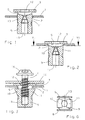
- the plastic nut is on average along the line I-I of Figure 4a shown, which is inserted into the component 1, which has the opening 2 for it.
- the plastic nut has the flange 3, which is in contact with the component 1 is determined when the plastic nut is fully inserted into component 1 is (see Figure 2).
- the flange 3 can be seen in FIGS. 4 and 5 Walls 5 and 6 or 7 and 8 connected to the nut piece 9, from which in The two snap hooks 10 and 11 grow out towards the flange 3, which are shown in their relaxed position as shown in FIG which they can be pushed through in the opening 2 of the component 1.
- Figure 3 shows the fully pushed through the opening 2 Screw 4, the two snap hooks when screwed into the nut piece 9 10 and 11 has pushed outwards, so with the flange 3 Apply facing surfaces to component 1.
- Figure 3 serves the plastic nut with the screw 4 screwed into it, on the Component 1 to attach the other component 14, which when tightening the Screw 4 is pressed from the head 15 to the flange 3.
- the nut piece 9 according to FIG. 3 still has the compared to FIGS. 1 and 2 Special feature that the screw hole 16 according to FIG. 3 is a Blind hole.
- FIGS. 5a and 5b is a modification compared to Figures 4a and 4b.
- Figures 5a and 5b namely the walls 7 and 8 with a weakening 18 in their central area provided, due to which the walls 7 and 8 inwards, ie towards snap on the snap hooks 10, 11, as shown in Figure 5b.
- the kink direction determined by the position of the weakening 17 or 18 is thereby to explain that in addition to the weakening, that is, in the corresponding thin part of the walls 5, 6 and 7, 8 a significant pressure concentration when Tightening the screw 4 results in the ones running in the material of the walls Print lines either to one side or to the other side of the Walls converge and concentrate there, with the pressure of each an oblique direction that corresponds to this pressure and thus a direction of buckling given is.
- 7a and 7b is a plastic nut in which the Walls 19, 20 each have two weakenings 21 and 22, of which the Attenuations 21 on the side facing away from the snap hooks 10, 11 and the Attenuations 22 are arranged on the side facing the snap hooks 10, 11 are.
- the result is a meandering shape Buckling of the walls 19 and 20, which creates a correspondingly large tolerance range can be bridged with this plastic nut.
Landscapes
- Engineering & Computer Science (AREA)
- General Engineering & Computer Science (AREA)
- Mechanical Engineering (AREA)
- Connection Of Plates (AREA)
- Bolts, Nuts, And Washers (AREA)
- Dowels (AREA)
- Slide Fasteners, Snap Fasteners, And Hook Fasteners (AREA)
- Sampling And Sample Adjustment (AREA)
- Supports Or Holders For Household Use (AREA)
Abstract
Description
- Figur 1
- einen Schnitt durch die Kunststoffmutter, der durch die Schnapphaken in Axialrichtung der Kunststoffmutter verläuft, und zwar beim Einführen in den Durchbruch eines Bauteils;
- Figur 2
- die gleiche Kunststoffmutter in einer Position vollständig durch den Durchbruch hindurchgeführt;
- Figur 3
- die Kunststoffmutter in der Position gemäß Figur 2 mit eingedrehter Schraube, wobei die Schnapphaken ausgespreizt sind, aber noch nicht an dem Bauteil anliegen.
- Figur 4a
- die Kunststoffmutter gemäß Figur 2 um 90° gedreht, wobei der Schnitt durch die Wände verläuft, an deren Innenseite die Schwächung angeordnet ist;
- Figur 4b
- die Kunststoffmutter gemäß Figur 4a mit nach außen geknickten Wänden bei fest angezogener Schraube;
- Figur 5a
- eine Kunststoffmutter ähnlich derjenigen gemäß Figur 4a, jedoch mit an der Außenseite der Wände angeordneter Schwächung;
- Figur 5b
- die Kunststoffmutter gemäß Figur 5a mit nach innen eingeknickten Wänden bei angezogener Schraube;
- Figur 6
- einen Schnitt längs der Linie VI-VI aus Figur 2;
- Figur 7a
- eine Kunststoffmutter mit zwei aufeinanderfolgenden Schwächungen in jeder Wand, die abwechselnd auf der den Schnapphaken zugewandten und abgewandten Seite liegen;
- Figur 7b
- die Kunststoffmutter gemäß Figur 7a mit nach innen und außen mäanderförmig abgeknickten Wänden bei angezogener Schraube.
Claims (6)
- Kunststoffmutter zur Aufnahme an einem einen Durchbruch (2) aufweisenden Bauteil (1), die mit einem ein Aufnahmeloch (12, 13) für eine Schraube (4) aufweisenden Mutterstück (9) in den Durchbruch (2) einsteckbar ist und zur Anlage an der einen Seite des Bauteils (1) mit einem Flansch (3) und zur Anlage an der anderen Seite des Bauteils (1) mit die Kunststoffmutter am Bauteil (1) sichernden Schnapphaken (10, 11) versehen ist, die in entspannter Lage einerseits in ihrer radialen Ausdehnung dem Innenmaß des Durchbruchs (2) entsprechen, andererseits das Aufnahmeloch (12, 13) überdecken und beim Einsetzen der Schraube (4) ausspreizen und sich dem Bauteil (1) gegenüberstellen, dadurch gekennzeichnet, dass neben den Schnapphaken (10, 11) in Ausspreizrichtung verlaufende Wände (5, 6, 7, 8; 19, 20) angeordnet sind, die sich vom Flansch (3) zum Mutterstück (9) erstrecken und in ihrem mittleren Bereich und in Ausspreizrichtung verlaufende derartige Schwächungen (17, 18; 21, 22) ihrer Wandstärke besitzen, dass beim Anziehen der Schraube (4) durch Knicken der Wände (5, 6, 7, 8; 19, 20) an den Schwächungen (17, 18; 21, 22) sich der Flansch (3) und die Schnapphaken (10, 11) beidseitig an dem Bauteil (1) anlegen.
- Kunststoffmutter nach Anspruch 1, dadurch gekennzeichnet, dass die Schwächung (17) der Wände (5, 6) auf deren den Schnapphaken (10, 11) zugewandten Seite angeordnet ist.
- Kunststoffmutter nach Anspruch 1, dadurch gekennzeichnet, dass die Schwächung (18) der Wände (7, 8) auf deren den Schnapphaken (10, 11) abgewandten Seite angeordnet ist.
- Kunststoffmutter nach Anspruch 1, dadurch gekennzeichnet, dass die Wände (19, 20) jeweils mehrere Schwächungen (21, 22) aufweisen, die abwechselnd auf der den Schnapphaken (10, 11) abgewandten und zugewandten Seite angeordnet sind.
- Kunststoffmutter nach einem der Ansprüche 1 bis 4, dadurch gekennzeichnet, dass das Aufnahmeloch für die Schraube (4) im Bereich der Wände (5, 6; 7, 8; 19, 20) als Durchgangsloch (12) und im Bereich des Mutterstücks (9) als Gewindeloch (13) ausgebildet ist.
- Kunststoffmutter nach Anspruch 5, dadurch gekennzeichnet, dass das Gewindeloch (13) als Sackloch (16) ausgebildet ist.
Applications Claiming Priority (2)
| Application Number | Priority Date | Filing Date | Title |
|---|---|---|---|
| DE10305610 | 2003-02-11 | ||
| DE10305610A DE10305610A1 (de) | 2003-02-11 | 2003-02-11 | Kunststoffmutter zur Aufnahme an einem einen Durchbruch aufweisenden Bauteil |
Publications (2)
| Publication Number | Publication Date |
|---|---|
| EP1447576A1 true EP1447576A1 (de) | 2004-08-18 |
| EP1447576B1 EP1447576B1 (de) | 2005-10-26 |
Family
ID=32668018
Family Applications (1)
| Application Number | Title | Priority Date | Filing Date |
|---|---|---|---|
| EP04002892A Expired - Lifetime EP1447576B1 (de) | 2003-02-11 | 2004-02-10 | Kunststoffmutter zur Aufnahme an einem einen Durchbruch aufweisenden Bauteil |
Country Status (9)
| Country | Link |
|---|---|
| US (1) | US7014405B2 (de) |
| EP (1) | EP1447576B1 (de) |
| JP (1) | JP2004245415A (de) |
| KR (1) | KR20040073358A (de) |
| CN (1) | CN1521412A (de) |
| AT (1) | ATE307985T1 (de) |
| BR (1) | BRPI0400177A (de) |
| DE (2) | DE10305610A1 (de) |
| ES (1) | ES2247567T3 (de) |
Cited By (4)
| Publication number | Priority date | Publication date | Assignee | Title |
|---|---|---|---|---|
| EP1918596A1 (de) * | 2006-11-03 | 2008-05-07 | Herbert Schruff | Blindnietelement sowie Verwendung hierfür |
| EP1767793A3 (de) * | 2005-09-23 | 2012-09-19 | HILTI Aktiengesellschaft | Befestigungsvorrichtung für die Befestigung von Solarpaneelen an einer Montageschiene |
| EP2960531A1 (de) * | 2014-06-27 | 2015-12-30 | Bollhoff Otalu S.A. | Werkstück zum festklemmen auf einer halterung, vorrichtung, die ein solches werkstück umfasst, und herstellungsverfahren eines solchen werkstücks und einer solchen vorrichtung |
| WO2017034875A1 (en) * | 2015-08-27 | 2017-03-02 | Alcoa Inc. | Fastener locking members |
Families Citing this family (24)
| Publication number | Priority date | Publication date | Assignee | Title |
|---|---|---|---|---|
| DE10235799A1 (de) * | 2002-08-05 | 2004-03-04 | Ejot Gmbh & Co. Kg | Kunststoffmutter zur Anbringung an einem Bauteil |
| EP1746293A1 (de) * | 2005-07-20 | 2007-01-24 | Joseph Talpe | Befestigungsvorrichtung für Hohlrahmen und ebene Flächen |
| WO2007074352A1 (en) * | 2005-12-29 | 2007-07-05 | Infineon Technologies Ag | Electronic component and a method of fabricating an electronic component |
| AU2006201156A1 (en) * | 2006-01-17 | 2007-08-02 | Cobra Fixations Cie. Ltee - Cobra Anchors Co. Ltd. | Plastic anchor for drywall, plaster, brick, concrete,etc |
| DE202006002173U1 (de) | 2006-02-10 | 2007-06-21 | Ejot Gmbh & Co. Kg | In einem Durchbruch einer Metallplatte einsetzbares Mutterteil |
| GB2449291B (en) * | 2007-05-17 | 2013-01-23 | Legrand Electric Ltd | Technique for securing components together |
| WO2009014611A2 (en) | 2007-07-20 | 2009-01-29 | Henkel Ag & Co. Kgaa | Molded polymeric spacing devices |
| EP2216554B1 (de) * | 2009-02-06 | 2012-04-18 | Fairchild Fasteners Europe - Camloc GmbH | Einweghülse |
| DE102010023992A1 (de) * | 2010-06-16 | 2011-12-22 | Volkswagen Ag | Anordnung zur Befestigung zumindest eines ersten Bauteils an einem zweiten Bauteil |
| ES2623527T3 (es) * | 2011-07-25 | 2017-07-11 | Faurecia Intérieur Industrie | Dispositivo de fijación para la fijación en una placa que tiene un orificio y conjunto que comprende dicho dispositivo de fijación |
| DE102013202723B4 (de) | 2013-02-20 | 2023-04-20 | Bayerische Motoren Werke Aktiengesellschaft | Befestigungsbaugruppe |
| KR20170040544A (ko) * | 2015-10-05 | 2017-04-13 | 삼성전자주식회사 | 냉장고용 내상 및 그 제조방법 |
| CN107509353A (zh) * | 2016-06-14 | 2017-12-22 | 伊姆西公司 | 用于机架的杆以及与机架配合使用的固定装置 |
| KR20190039711A (ko) | 2016-08-12 | 2019-04-15 | 일리노이즈 툴 워크스 인코포레이티드 | 리벳 파스너 조립체 |
| DE102017107162A1 (de) | 2017-04-04 | 2018-10-04 | Eberspächer Exhaust Technology GmbH & Co. KG | Montagebaugruppe |
| US10927876B1 (en) * | 2017-11-02 | 2021-02-23 | Robert Rosebrugh | Rivet nut fastener |
| DE102019101078A1 (de) | 2018-01-16 | 2019-07-18 | Illinois Tool Works Inc. | Niet-befestigungselementanordnung und verfahren zu ihrer verwendung |
| EP3581319B1 (de) | 2018-05-09 | 2023-12-13 | Brigham Young University | System und verfahren zur friktionsbitverbindung |
| US11268557B2 (en) | 2018-10-10 | 2022-03-08 | Illinois Tool Works Inc. | Rivet fastener assembly and method of use thereof |
| CN109630936A (zh) * | 2018-12-29 | 2019-04-16 | 贵派电器股份有限公司 | 一种抗振灯具 |
| CN111219059A (zh) * | 2020-03-01 | 2020-06-02 | 广西盛虎金属制品有限公司 | 施工用紧固件 |
| NL2027443B1 (en) * | 2021-01-27 | 2022-09-02 | Walraven Holding Bv J Van | Fastening assembly |
| CN116395034B (zh) * | 2022-11-30 | 2025-02-28 | 上汽通用五菱汽车股份有限公司 | 一种连续碳纤维增强的汽车b柱 |
| FR3149357B1 (fr) * | 2023-05-30 | 2025-07-11 | Airbus Operations Sas | Dispositif d’attache rapide d’au moins un accessoire sur un support, systeme et aeronef correspondants |
Citations (2)
| Publication number | Priority date | Publication date | Assignee | Title |
|---|---|---|---|---|
| US3343441A (en) * | 1965-04-01 | 1967-09-26 | United Carr Inc | Self-securing fastener |
| DE19728988A1 (de) * | 1997-07-07 | 1999-01-14 | Ejot Verbindungstech Gmbh & Co | Kunststoffmutter zum Verbinden von plattenartigen Teilen |
Family Cites Families (9)
| Publication number | Priority date | Publication date | Assignee | Title |
|---|---|---|---|---|
| US3313083A (en) * | 1963-05-29 | 1967-04-11 | Tinnerman Products Inc | Deformable plastic fastener |
| JPS5514359A (en) * | 1978-07-18 | 1980-01-31 | Nifco Inc | Panel fitting instrument |
| ES255417Y (es) * | 1979-01-25 | 1982-10-16 | dispositivo sujetador perfeccionado . | |
| US4312612A (en) * | 1979-05-31 | 1982-01-26 | United Packages Limited | Screw fixing device |
| US5078561A (en) * | 1990-11-08 | 1992-01-07 | Illinois Tools Works, Inc. | Plastic expansion nut |
| US5690454A (en) * | 1992-11-23 | 1997-11-25 | Dry Dock Industries, Inc. | Anchoring retainer for threaded fasteners |
| JP2599730Y2 (ja) * | 1993-08-02 | 1999-09-20 | ポップリベット・ファスナー株式会社 | カーペット等のクリップ |
| DE59701255D1 (de) | 1996-09-25 | 2000-04-20 | Ejot Verbindungstech Gmbh & Co | Kunststoffmutter zum verbinden von plattenartigen teilen |
| JP2000329121A (ja) * | 1999-05-19 | 2000-11-28 | Nippon Pop Rivets & Fasteners Ltd | スクリューグロメット |
-
2003
- 2003-02-11 DE DE10305610A patent/DE10305610A1/de not_active Withdrawn
-
2004
- 2004-02-04 BR BR0400177-0A patent/BRPI0400177A/pt not_active Application Discontinuation
- 2004-02-10 CN CNA2004100053039A patent/CN1521412A/zh active Pending
- 2004-02-10 AT AT04002892T patent/ATE307985T1/de not_active IP Right Cessation
- 2004-02-10 EP EP04002892A patent/EP1447576B1/de not_active Expired - Lifetime
- 2004-02-10 ES ES04002892T patent/ES2247567T3/es not_active Expired - Lifetime
- 2004-02-10 JP JP2004033227A patent/JP2004245415A/ja active Pending
- 2004-02-10 DE DE502004000111T patent/DE502004000111D1/de not_active Expired - Lifetime
- 2004-02-11 KR KR1020040009075A patent/KR20040073358A/ko not_active Withdrawn
- 2004-02-11 US US10/775,105 patent/US7014405B2/en not_active Expired - Lifetime
Patent Citations (2)
| Publication number | Priority date | Publication date | Assignee | Title |
|---|---|---|---|---|
| US3343441A (en) * | 1965-04-01 | 1967-09-26 | United Carr Inc | Self-securing fastener |
| DE19728988A1 (de) * | 1997-07-07 | 1999-01-14 | Ejot Verbindungstech Gmbh & Co | Kunststoffmutter zum Verbinden von plattenartigen Teilen |
Cited By (11)
| Publication number | Priority date | Publication date | Assignee | Title |
|---|---|---|---|---|
| EP1767793A3 (de) * | 2005-09-23 | 2012-09-19 | HILTI Aktiengesellschaft | Befestigungsvorrichtung für die Befestigung von Solarpaneelen an einer Montageschiene |
| EP1918596A1 (de) * | 2006-11-03 | 2008-05-07 | Herbert Schruff | Blindnietelement sowie Verwendung hierfür |
| US7901171B2 (en) | 2006-11-03 | 2011-03-08 | Herbert Schruff | Blind fastener and method |
| EP2960531A1 (de) * | 2014-06-27 | 2015-12-30 | Bollhoff Otalu S.A. | Werkstück zum festklemmen auf einer halterung, vorrichtung, die ein solches werkstück umfasst, und herstellungsverfahren eines solchen werkstücks und einer solchen vorrichtung |
| FR3022962A1 (fr) * | 2014-06-27 | 2016-01-01 | Bollhoff Otalu Sa | Piece a sertir sur un support, dispositif comprenant une telle piece et procedes de fabrication d'une telle piece et d'un tel dispositif |
| FR3049665A1 (fr) * | 2014-06-27 | 2017-10-06 | Bollhoff Otalu Sa | Piece a sertir sur un support, dispositif comprenant une telle piece et procedes de fabrication d'une telle piece et d'un tel dispositif |
| US9903402B2 (en) | 2014-06-27 | 2018-02-27 | Bollhoff Otalu S.A. | Piece to be crimped on a support, device comprising such a piece and methods for manufacturing such a piece and such a device |
| WO2017034875A1 (en) * | 2015-08-27 | 2017-03-02 | Alcoa Inc. | Fastener locking members |
| CN106481635A (zh) * | 2015-08-27 | 2017-03-08 | 美铝公司 | 紧固件锁定构件 |
| US10215218B2 (en) | 2015-08-27 | 2019-02-26 | Arconic Inc. | Fastener locking members |
| US10683887B2 (en) | 2015-08-27 | 2020-06-16 | Arconic Inc. | Fastener locking members |
Also Published As
| Publication number | Publication date |
|---|---|
| BRPI0400177A (pt) | 2004-12-28 |
| KR20040073358A (ko) | 2004-08-19 |
| JP2004245415A (ja) | 2004-09-02 |
| US7014405B2 (en) | 2006-03-21 |
| US20040156694A1 (en) | 2004-08-12 |
| ES2247567T3 (es) | 2006-03-01 |
| ATE307985T1 (de) | 2005-11-15 |
| DE502004000111D1 (de) | 2005-12-01 |
| EP1447576B1 (de) | 2005-10-26 |
| CN1521412A (zh) | 2004-08-18 |
| DE10305610A1 (de) | 2004-08-19 |
Similar Documents
| Publication | Publication Date | Title |
|---|---|---|
| EP1447576B1 (de) | Kunststoffmutter zur Aufnahme an einem einen Durchbruch aufweisenden Bauteil | |
| DE808510C (de) | Einsatzkoerper zum Einschrauben in Bauteile und zur Aufnahme einer Maschinenschraube | |
| DE29916793U1 (de) | Befestigungssystem | |
| DE10357844B4 (de) | Befestigungssystem | |
| DE10034968B4 (de) | Befestigungsclip | |
| EP3478975B1 (de) | Clip mit einem kopf und einem sich entlang einer längsachse von dem kopf erstreckenden schaft | |
| WO2009097842A9 (de) | Steckvorrichtung | |
| DE4444467C2 (de) | Gewindeschneidschraube | |
| DE102012208482A1 (de) | Befestigungsvorrichtung | |
| DE102009024264A1 (de) | Befestigungselement, insbesondere Mutter | |
| DE202020101103U1 (de) | Rohrschelle sowie Baukasten für ihre Erstellung | |
| DE102008036386B4 (de) | Rohrschelle und Profilelement für eine Rohrschelle | |
| DE202008007378U1 (de) | Schraubclip | |
| DE20312075U1 (de) | Vorrichtung mit zwei durch eine Verbindungsschraube zusammengehaltenen Hohlprofilen sowie Werkzeug dazu | |
| EP1039043B1 (de) | Sanitärarmatur mit einer Mutter zur Befestigung | |
| EP3372916B1 (de) | System zur lösbaren befestigung eines bauteils einer klima- und raumlufttechnischen anlage | |
| DE202010009496U1 (de) | Verliersicher gehaltene Schraube | |
| DE10304514A1 (de) | Fixierteil für eine Schlauchschelle | |
| DE2905753C2 (de) | ||
| DE102006005784A1 (de) | Spritze | |
| DE19647209C2 (de) | Befestigungsvorrichtung aus Kunststoff | |
| DE102018122701A1 (de) | Haltersystem zur Befestigung eines Behälters an einem Fahrzeug | |
| DE3441562A1 (de) | Rohrschelle | |
| DE29601547U1 (de) | Leitungsdurchführung mit Verdrehsicherung | |
| DE102006052379A1 (de) | Schraube |
Legal Events
| Date | Code | Title | Description |
|---|---|---|---|
| PUAI | Public reference made under article 153(3) epc to a published international application that has entered the european phase |
Free format text: ORIGINAL CODE: 0009012 |
|
| AK | Designated contracting states |
Kind code of ref document: A1 Designated state(s): AT BE BG CH CY CZ DE DK EE ES FI FR GB GR HU IE IT LI LU MC NL PT RO SE SI SK TR |
|
| AX | Request for extension of the european patent |
Extension state: AL LT LV MK |
|
| 17P | Request for examination filed |
Effective date: 20040730 |
|
| 17Q | First examination report despatched |
Effective date: 20040915 |
|
| GRAP | Despatch of communication of intention to grant a patent |
Free format text: ORIGINAL CODE: EPIDOSNIGR1 |
|
| AKX | Designation fees paid |
Designated state(s): AT BE BG CH CY CZ DE DK EE ES FI FR GB GR HU IE IT LI LU MC NL PT RO SE SI SK TR |
|
| GRAS | Grant fee paid |
Free format text: ORIGINAL CODE: EPIDOSNIGR3 |
|
| GRAA | (expected) grant |
Free format text: ORIGINAL CODE: 0009210 |
|
| AK | Designated contracting states |
Kind code of ref document: B1 Designated state(s): AT BE BG CH CY CZ DE DK EE ES FI FR GB GR HU IE IT LI LU MC NL PT RO SE SI SK TR |
|
| PG25 | Lapsed in a contracting state [announced via postgrant information from national office to epo] |
Ref country code: CZ Free format text: LAPSE BECAUSE OF FAILURE TO SUBMIT A TRANSLATION OF THE DESCRIPTION OR TO PAY THE FEE WITHIN THE PRESCRIBED TIME-LIMIT Effective date: 20051026 Ref country code: FI Free format text: LAPSE BECAUSE OF FAILURE TO SUBMIT A TRANSLATION OF THE DESCRIPTION OR TO PAY THE FEE WITHIN THE PRESCRIBED TIME-LIMIT Effective date: 20051026 Ref country code: IE Free format text: LAPSE BECAUSE OF FAILURE TO SUBMIT A TRANSLATION OF THE DESCRIPTION OR TO PAY THE FEE WITHIN THE PRESCRIBED TIME-LIMIT Effective date: 20051026 Ref country code: SI Free format text: LAPSE BECAUSE OF FAILURE TO SUBMIT A TRANSLATION OF THE DESCRIPTION OR TO PAY THE FEE WITHIN THE PRESCRIBED TIME-LIMIT Effective date: 20051026 Ref country code: SK Free format text: LAPSE BECAUSE OF FAILURE TO SUBMIT A TRANSLATION OF THE DESCRIPTION OR TO PAY THE FEE WITHIN THE PRESCRIBED TIME-LIMIT Effective date: 20051026 Ref country code: RO Free format text: LAPSE BECAUSE OF FAILURE TO SUBMIT A TRANSLATION OF THE DESCRIPTION OR TO PAY THE FEE WITHIN THE PRESCRIBED TIME-LIMIT Effective date: 20051026 Ref country code: NL Free format text: LAPSE BECAUSE OF FAILURE TO SUBMIT A TRANSLATION OF THE DESCRIPTION OR TO PAY THE FEE WITHIN THE PRESCRIBED TIME-LIMIT Effective date: 20051026 |
|
| REG | Reference to a national code |
Ref country code: GB Ref legal event code: FG4D Free format text: NOT ENGLISH |
|
| REG | Reference to a national code |
Ref country code: CH Ref legal event code: EP Ref country code: CH Ref legal event code: NV Representative=s name: A. BRAUN, BRAUN, HERITIER, ESCHMANN AG PATENTANWAE |
|
| GBT | Gb: translation of ep patent filed (gb section 77(6)(a)/1977) |
Effective date: 20051026 |
|
| REG | Reference to a national code |
Ref country code: IE Ref legal event code: FG4D Free format text: LANGUAGE OF EP DOCUMENT: GERMAN |
|
| REF | Corresponds to: |
Ref document number: 502004000111 Country of ref document: DE Date of ref document: 20051201 Kind code of ref document: P |
|
| PG25 | Lapsed in a contracting state [announced via postgrant information from national office to epo] |
Ref country code: GR Free format text: LAPSE BECAUSE OF FAILURE TO SUBMIT A TRANSLATION OF THE DESCRIPTION OR TO PAY THE FEE WITHIN THE PRESCRIBED TIME-LIMIT Effective date: 20060126 Ref country code: SE Free format text: LAPSE BECAUSE OF FAILURE TO SUBMIT A TRANSLATION OF THE DESCRIPTION OR TO PAY THE FEE WITHIN THE PRESCRIBED TIME-LIMIT Effective date: 20060126 Ref country code: BG Free format text: LAPSE BECAUSE OF FAILURE TO SUBMIT A TRANSLATION OF THE DESCRIPTION OR TO PAY THE FEE WITHIN THE PRESCRIBED TIME-LIMIT Effective date: 20060126 Ref country code: DK Free format text: LAPSE BECAUSE OF FAILURE TO SUBMIT A TRANSLATION OF THE DESCRIPTION OR TO PAY THE FEE WITHIN THE PRESCRIBED TIME-LIMIT Effective date: 20060126 |
|
| PG25 | Lapsed in a contracting state [announced via postgrant information from national office to epo] |
Ref country code: AT Free format text: LAPSE BECAUSE OF NON-PAYMENT OF DUE FEES Effective date: 20060210 |
|
| PG25 | Lapsed in a contracting state [announced via postgrant information from national office to epo] |
Ref country code: MC Free format text: LAPSE BECAUSE OF NON-PAYMENT OF DUE FEES Effective date: 20060228 Ref country code: LU Free format text: LAPSE BECAUSE OF NON-PAYMENT OF DUE FEES Effective date: 20060228 Ref country code: BE Free format text: LAPSE BECAUSE OF NON-PAYMENT OF DUE FEES Effective date: 20060228 |
|
| REG | Reference to a national code |
Ref country code: ES Ref legal event code: FG2A Ref document number: 2247567 Country of ref document: ES Kind code of ref document: T3 |
|
| PG25 | Lapsed in a contracting state [announced via postgrant information from national office to epo] |
Ref country code: PT Free format text: LAPSE BECAUSE OF FAILURE TO SUBMIT A TRANSLATION OF THE DESCRIPTION OR TO PAY THE FEE WITHIN THE PRESCRIBED TIME-LIMIT Effective date: 20060327 |
|
| NLV1 | Nl: lapsed or annulled due to failure to fulfill the requirements of art. 29p and 29m of the patents act | ||
| PG25 | Lapsed in a contracting state [announced via postgrant information from national office to epo] |
Ref country code: HU Free format text: LAPSE BECAUSE OF FAILURE TO SUBMIT A TRANSLATION OF THE DESCRIPTION OR TO PAY THE FEE WITHIN THE PRESCRIBED TIME-LIMIT Effective date: 20060427 |
|
| REG | Reference to a national code |
Ref country code: IE Ref legal event code: FD4D |
|
| ET | Fr: translation filed | ||
| PLBE | No opposition filed within time limit |
Free format text: ORIGINAL CODE: 0009261 |
|
| STAA | Information on the status of an ep patent application or granted ep patent |
Free format text: STATUS: NO OPPOSITION FILED WITHIN TIME LIMIT |
|
| 26N | No opposition filed |
Effective date: 20060727 |
|
| BERE | Be: lapsed |
Owner name: EJOT G.M.B.H. & CO. KG Effective date: 20060228 |
|
| PGFP | Annual fee paid to national office [announced via postgrant information from national office to epo] |
Ref country code: CH Payment date: 20080129 Year of fee payment: 5 |
|
| PGFP | Annual fee paid to national office [announced via postgrant information from national office to epo] |
Ref country code: IT Payment date: 20080227 Year of fee payment: 5 |
|
| REG | Reference to a national code |
Ref country code: CH Ref legal event code: PFA Owner name: EJOT GMBH & CO. KG Free format text: EJOT GMBH & CO. KG#UNTERE BIENHECKE#57334 BAD LAASPHE (DE) -TRANSFER TO- EJOT GMBH & CO. KG#UNTERE BIENHECKE#57334 BAD LAASPHE (DE) |
|
| PG25 | Lapsed in a contracting state [announced via postgrant information from national office to epo] |
Ref country code: EE Free format text: LAPSE BECAUSE OF FAILURE TO SUBMIT A TRANSLATION OF THE DESCRIPTION OR TO PAY THE FEE WITHIN THE PRESCRIBED TIME-LIMIT Effective date: 20051026 |
|
| PG25 | Lapsed in a contracting state [announced via postgrant information from national office to epo] |
Ref country code: CY Free format text: LAPSE BECAUSE OF FAILURE TO SUBMIT A TRANSLATION OF THE DESCRIPTION OR TO PAY THE FEE WITHIN THE PRESCRIBED TIME-LIMIT Effective date: 20051026 |
|
| PGFP | Annual fee paid to national office [announced via postgrant information from national office to epo] |
Ref country code: ES Payment date: 20090317 Year of fee payment: 6 |
|
| PGFP | Annual fee paid to national office [announced via postgrant information from national office to epo] |
Ref country code: GB Payment date: 20090204 Year of fee payment: 6 |
|
| REG | Reference to a national code |
Ref country code: CH Ref legal event code: PL |
|
| PG25 | Lapsed in a contracting state [announced via postgrant information from national office to epo] |
Ref country code: LI Free format text: LAPSE BECAUSE OF NON-PAYMENT OF DUE FEES Effective date: 20090228 Ref country code: CH Free format text: LAPSE BECAUSE OF NON-PAYMENT OF DUE FEES Effective date: 20090228 |
|
| PGFP | Annual fee paid to national office [announced via postgrant information from national office to epo] |
Ref country code: TR Payment date: 20100204 Year of fee payment: 7 |
|
| GBPC | Gb: european patent ceased through non-payment of renewal fee |
Effective date: 20100210 |
|
| REG | Reference to a national code |
Ref country code: ES Ref legal event code: FD2A Effective date: 20110329 |
|
| PG25 | Lapsed in a contracting state [announced via postgrant information from national office to epo] |
Ref country code: GB Free format text: LAPSE BECAUSE OF NON-PAYMENT OF DUE FEES Effective date: 20100210 Ref country code: IT Free format text: LAPSE BECAUSE OF NON-PAYMENT OF DUE FEES Effective date: 20090210 |
|
| PG25 | Lapsed in a contracting state [announced via postgrant information from national office to epo] |
Ref country code: ES Free format text: LAPSE BECAUSE OF NON-PAYMENT OF DUE FEES Effective date: 20110316 |
|
| PG25 | Lapsed in a contracting state [announced via postgrant information from national office to epo] |
Ref country code: ES Free format text: LAPSE BECAUSE OF NON-PAYMENT OF DUE FEES Effective date: 20100211 |
|
| PG25 | Lapsed in a contracting state [announced via postgrant information from national office to epo] |
Ref country code: TR Free format text: LAPSE BECAUSE OF NON-PAYMENT OF DUE FEES Effective date: 20110210 |
|
| PGFP | Annual fee paid to national office [announced via postgrant information from national office to epo] |
Ref country code: FR Payment date: 20140227 Year of fee payment: 11 |
|
| REG | Reference to a national code |
Ref country code: FR Ref legal event code: ST Effective date: 20151030 |
|
| PG25 | Lapsed in a contracting state [announced via postgrant information from national office to epo] |
Ref country code: FR Free format text: LAPSE BECAUSE OF NON-PAYMENT OF DUE FEES Effective date: 20150302 |
|
| PGFP | Annual fee paid to national office [announced via postgrant information from national office to epo] |
Ref country code: DE Payment date: 20180227 Year of fee payment: 15 |
|
| REG | Reference to a national code |
Ref country code: DE Ref legal event code: R119 Ref document number: 502004000111 Country of ref document: DE |
|
| PG25 | Lapsed in a contracting state [announced via postgrant information from national office to epo] |
Ref country code: DE Free format text: LAPSE BECAUSE OF NON-PAYMENT OF DUE FEES Effective date: 20190903 |