EP1447801A2 - Appareil d'enregistrement/lecture du type à encartement - Google Patents
Appareil d'enregistrement/lecture du type à encartement Download PDFInfo
- Publication number
- EP1447801A2 EP1447801A2 EP04250731A EP04250731A EP1447801A2 EP 1447801 A2 EP1447801 A2 EP 1447801A2 EP 04250731 A EP04250731 A EP 04250731A EP 04250731 A EP04250731 A EP 04250731A EP 1447801 A2 EP1447801 A2 EP 1447801A2
- Authority
- EP
- European Patent Office
- Prior art keywords
- disk
- slot
- base plate
- eject
- arm
- Prior art date
- Legal status (The legal status is an assumption and is not a legal conclusion. Google has not performed a legal analysis and makes no representation as to the accuracy of the status listed.)
- Withdrawn
Links
- 230000007246 mechanism Effects 0.000 claims abstract description 170
- 238000003825 pressing Methods 0.000 claims description 10
- 230000008878 coupling Effects 0.000 claims description 7
- 238000010168 coupling process Methods 0.000 claims description 7
- 238000005859 coupling reaction Methods 0.000 claims description 7
- 230000009191 jumping Effects 0.000 abstract description 3
- 238000000034 method Methods 0.000 description 11
- 210000000078 claw Anatomy 0.000 description 5
- 238000003780 insertion Methods 0.000 description 3
- 230000037431 insertion Effects 0.000 description 3
- 229920003002 synthetic resin Polymers 0.000 description 3
- 239000000057 synthetic resin Substances 0.000 description 3
- 230000001678 irradiating effect Effects 0.000 description 2
- 239000002184 metal Substances 0.000 description 2
- 229910000831 Steel Inorganic materials 0.000 description 1
- 230000003213 activating effect Effects 0.000 description 1
- 238000013016 damping Methods 0.000 description 1
- 238000004519 manufacturing process Methods 0.000 description 1
- 238000012986 modification Methods 0.000 description 1
- 230000004048 modification Effects 0.000 description 1
- 230000009467 reduction Effects 0.000 description 1
- 238000009751 slip forming Methods 0.000 description 1
- 239000010959 steel Substances 0.000 description 1
Images


Classifications
-
- G—PHYSICS
- G11—INFORMATION STORAGE
- G11B—INFORMATION STORAGE BASED ON RELATIVE MOVEMENT BETWEEN RECORD CARRIER AND TRANSDUCER
- G11B17/00—Guiding record carriers not specifically of filamentary or web form, or of supports therefor
- G11B17/02—Details
- G11B17/04—Feeding or guiding single record carrier to or from transducer unit
- G11B17/0401—Details
- G11B17/0402—Servo control
- G11B17/0404—Servo control with parallel drive rollers
Definitions
- the present invention relates to a slot-in type reproducing/recording apparatus having a slot for inserting and ejecting a disk.
- a reproducing/recording apparatus is used for reproducing data from or recording data on a disk.
- Such reproducing/recording apparatus includes an apparatus body that has a slot for inserting and ejecting a disk and a reproducing/recording mechanism that is provided inside the apparatus body for reproducing data from and recording data on the disk.
- a slot-in type one in which a disk is directly inserted into the slot formed on the apparatus body is available.
- the slot-in type reproducing/recording apparatus there is a conventional one that has a pair of upper and lower rolls for pulling-in and pushing-out a disk to and from the apparatus body.
- the pair of rolls typically made of rubber or the like, sandwiches both surfaces of the disk.
- An object of the present invention is to provide a slot-in type reproducing/recording apparatus in which a disk ,when ejected, stops at a predetermined position in front of the apparatus to be easily handled.
- a slot-in type reproducing/recording apparatus includes: an apparatus body having a slot for inserting and ejecting a disk; and a hold assembly provided inside the apparatus body for accommodating the disk, the hold assembly including a selector plate provided on a base plate, an eject arm for pressing the disk and ejecting the disk toward the slot, a main arm turnably attached to the base plate for pressing the disk, and a stop mechanism for stopping eject operation when the disk is ejected from the slot by the main arm and the eject arm, the selector plate being able to advance and retract in a direction orthogonal to a disk-eject direction of the eject arm within a plane parallel to the base plate in accordance with open/close operation of the main arm, the stop mechanism having an engagement pin formed on the eject arm and biased toward the selector plate and an engagement recess formed on the selector plate for holding the engagement pin so that the disk is held by the main arm and the eject arm.
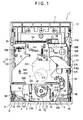
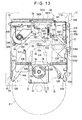
- Fig. 1 is a plan view of whole inner structure according to the present embodiment.
- a slot-in type reproducing/recording apparatus includes an apparatus body 1 having a slot 1A provided on a front surface for inserting and ejecting a disk, a recording/reproducing mechanism 2 and a base plate 3 each provided inside the apparatus body 1, a loading mechanism 4 for advancing and retracting the base plate 3, a hold assembly 5 provided on the base plate 3 for holding the disk, and a shutter 6 turnably provided on the apparatus body 1 for opening and closing the slot 1A.
- the apparatus body 1 includes a housing 11 made of synthetic resin, a bottom plate (not shown) attached to a bottom of the housing 11, a substantially box-shaped upper lid 12 that is held by an edge of the bottom plate and covers the housing 11, and an electric circuit board (not shown) attached to an under surface of the housing 11.
- the bottom plate and the upper lid 12 are integrally formed of sheet metal.
- Fig. 2 is a plan view of the inner structure shown in Fig. 1 of the present embodiment, where the base plate 3 and the hold assembly 5 are removed.
- the recording/reproducing mechanism 2 is an apparatus for recording data on and/or reproducing data from the disk while irradiating a laser beam onto the disk, the recording/reproducing mechanism 2 including a base 21, a rotary table 22 attached to the base 21 for the disk to be placed on, a recording/reproduction mechanism body 23 for irradiating the laser beam onto the disk placed on the rotary table 22 and reading a light reflected by the disk, and a drive mechanism 24 for advancing and retracting the recording/reproducing mechanism body 23 along a radial direction of the disk.
- the rotary table 22, the recording/reproducing mechanism body 23 and the drive mechanism 24 are configured in the same manner as in a tray type reproducing/recording apparatus.
- an end thereof (the upper side in Fig. 2) is turnably supported by the housing 11 while the other end (the lower side in Fig. 2) is swingable toward and away form the disk accommodated in the hold assembly 5.
- a swing mechanism 25 for swinging the base 21 is provided at the other end of the base 21.
- the drive mechanism 24 includes a motor (not shown) for advancing and retracting the recording/reproducing mechanism body 23 along a guide rod (not shown).
- the base plate 3 includes a flat section 31 and folded sections 32 which are formed by folding both side edges of the flat section 31 (see Fig. 3), the flat section 31 and the folded sections 32 being integrally formed of sheet metal.
- a clamper 70 for holding the disk and a clamper hold mechanism 7 for moving the clamper 70 toward the disk when the base plate 3 advances to the recording/reproducing mechanism 2 and for moving the clamper 70 away from the disk when the base plate 3 retracts to the slot 1A.
- the clamper 70 includes a circular plate 71 located on an upper side of the flat section 31, a circular holding portion (not shown) located to face the circular plate 71 sandwiching the flat section 31 therebetween and held in a hole of the disk, and a cylinder 72 for coupling the circular plate 71 and the circular holding portion.
- the circular holding portion includes a steel plate (not shown) that sticks to a magnet (not shown) of the rotary table 22.
- the clamper hold mechanism 7 includes a plate-shaped holder 7A that can advance and retract, with guide by a guide 31 A of the flat section 31, in an advancement and retraction direction of the base plate 3, the holder 7A being provided with a substantially U-shaped aperture at an end facing the cylinder 72 of the clamper 70 and also provided with cam portions 7B at ends of the aperture for moving the circular plate 71 upward.
- an engagement projection 7C that is engagable with an engagement projection 12A formed on a ceiling of the upper lid 12.
- the clamper hold mechanism 7 when the base plate 3 retracts (moves to the lower side in Fig. 1), the clamper 70 moves toward the stopped holder 7A so that the cam portions 7B lift the circular plate 71. Then the clamper 70 moves away from the disk and the clamp is released. With the clamp of the clamper 70 being released, the disk can be accommodated in the hold assembly 5.
- the loading mechanism 4 advances and retracts the base plate 3 between a position where the disk faces the recording/reproducing mechanism 2 (advancement position) and a position near the slot (retraction position), the loading mechanism 4 including a motor 41 attached to the housing 11 and adapted to operate when the base plate 3 reaches a predetermined advancement starting position and end its operation when the base plate 3 reaches an advancement ending position, a gear mechanism 42 coupled with the motor 41, and a rack 43 coupled with the gear mechanism 42 and provided on the folded section 32 of the base plate 3 along the advancement and retraction direction of the base plate (see Fig. 3).
- the motor 41 includes a switch lever 41A for executing rotation operation when positioned at the center in Fig.2 and stopping the rotation operation when located at the left and right sides.
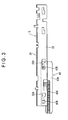
- Fig. 3 shows a longitudinal section of the base plate 3.
- the folded section 32 of the base plate 3 has two grooves 32A formed in line for allowing a relative movement of the rack 43 and the base plate 3 along the advancement and retraction direction.
- the rack 43 includes an attachment portion 43A extended toward the advancement and retraction direction, engagement portions 43B formed on the attachment portion 43A so as to engage with the grooves 32A, and a rack body 43C formed under the attachment portion 43A, all of which being integrally molded of synthetic resin.
- the gear mechanism 42 includes a pulley 42B coupled with a rotary shaft 4 1 B of the motor 41 through a belt 42A, a first gear 42C disposed to be coaxial with the pulley 42B, a second gear 42D that meshes with the first gear 42C, a third gear 42E that meshes with the second gear 42D, a forth gear 42F that meshes with the third gear 42E, a fifth gear 42G that meshes with the forth gear 42F, a sixth gear 42H that meshes with the fifth gear 42G, and a seventh gear 42I that meshes with the sixth gear 42H and can mesh with the rack 43.
- the motor 41 is connected to a controller (not shown) that controls, when the disk is ejected, an initial position of the base plate 3 so as to allow predetermined play in the advancement direction of the base plate 3 (see Fig. 3). Therefore, at the time of the disk insertion, the base plate 3 can advance to a predetermined position without any interference.
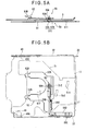
- Figs. 4 to 6 are illustrations each showing detailed structure of the hold assembly 5.
- Fig. 4 is a plan view showing the hold assembly 5.
- the hold assembly 5 includes a selector plate 51 provided on the base plate 3 to be movable in a level and in a direction orthogonal to the advancement and retraction direction of the base plate 3, an eject arm 52 for pressing an outer circumferential edge of the disk to eject the disk toward the slot 1A, two main arms 53 and 54 that are turnably attached to the base plate 3 and respectively press the outer circumferential edge of the disk, an engagement pin 55 provided on the eject arm 52, and a damper mechanism 50 for softening push-out force of the disk pushed out by the eject arm 52.
- the eject arm 52 as shown in Figs 4, 5A and 5B, includes a plate-shaped arm body 52A that is substantially U-shaped in plan view, two abutment portions 52B respectively provided on aperture ends of the arm body 52A and capable of abutting on the outer circumference of the disk, and engagement portions 52C formed on an upper surface of the arm body 52A so as to engage with elongated grooves 3B of the base plate 3.
- the arm body 52 A, the abutment portions 52B and the engagement portions 52C are integrally formed of synthetic resin.
- the eject arm 52 is coupled with an end of an arm member 52D, and the other end of the arm member 52D is turnably supported by the base plate 3. Between the arm member 52D and the base plate 3, there is a spring 52E that turns the arm member 52D in clockwise direction in Fig. 4 and constantly biases the eject arm 52 toward the slot 1A.
- the damper mechanism 50 includes a large gear 50A provided on the other end of the arm member 52D and a small gear 50B rotatably provided on the base plate 3 to mesh with the large gear 50A. Since the small gear 50B functions as a damper, damping force of the small gear 50B reduces pressing force when biasing force of the spring 52E pushes out the eject arm 52.
- the main arms 53 and 54 are respectively adapted to press the outer circumferential edge of the disk at different points with predetermined biasing force.
- the main arm 53 shown in the right side in Fig. 1, includes a flat-plate shaped arm body 53A and an abutment portion 53B that is provided at a front end of the arm body 53A and capable of abutting on the outer circumference of the disk.
- a rear end of the arm body 53A is turnably supported around a turn pin 53C attached to the flat section 31.
- the main arm 54 shown in the left side in Fig. 4, includes a flat-plate shaped arm body 54A and an abutment portion 54B that is provided at a front end of the arm body 54A and capable of abutting on the outer circumference of the disk.
- a center part of the arm body 54A is turnably supported around a turn pin 54C attached to the flat section 31.
- Two engagement elongated-holes 51A are formed in line on the selector plate 51 along the direction orthogonal to the advancement and retraction direction of the base plate 3.
- the engagement elongated-holes 51 A respectively engage with tip ends of the turn pins 53C and 54C.
- An engagement elongated-hole 51B is formed near a front end of the main arm 53 of the selector plate 51 along the advancement and retraction direction of the base plate 3.
- the engagement elongated-hole 51B engage with a tip end of an engagement pin 53D formed at the front end of the main arm 53.
- An engagement elongated-hole 51 C is formed near a rear end of the main arm 54 of the selector plate 51 along the advancement and retraction direction of the base plate 3.
- the engagement elongated-hole 51 C engages with a tip end of an engagement pin 54D formed at the rear end of the main arm 54.
- the engagement pins 53D and 54D respectively engage with the engagement elongated-holes 51B and 51C so that the selector plate 51 moves toward one direction (the right direction in Fig. 4) orthogonal to the advancement and retraction direction of the base plate 3.
- the selector plate 51 is biased toward the other direction (the left direction in Fig. 4) by a coil spring 5A. Therefore, the selector plate 51 moves toward the other direction, so that the main arms 53 and 54 close.
- the selector plate 51 As a rear end of the selector plate 51 is coupled with a spring-holding projection 33 formed at a rear left comer of the base plate 3 through the coil spring 5A, the selector plate 51 is biased toward the left direction in Fig. 4 with the biasing force of the coil spring 5A. Accordingly, the main arms 53 and 54 are constantly biased toward a closing direction.
- the engagement pin 55 as shown in Figs. 5A, 5B and 6, includes a substantially columnar pin body 55A, a rod 55B fixed to the pin body 55A at an end and turnably supported by the arm body 52A of the eject arm 52 at a center part, and a spring 55C disposed between the rod 55B and the arm body 52A for biasing the pin body 55A toward the selector plate 51.
- the other end of the rod 55B can abut on a cam member 55D provided on the folded section 32 of the base plate 3 to be advancable and retractable along a movement direction of the base plate 3.
- the cam member 55D includes a projection 55E projected outward from the folded section 32, the projection 55E being capable of abutting on a projection (not shown) formed on the housing 11.
- the hold assembly 5 includes an arm lock mechanism 56, an arm unlock mechanism 57, and base-plate advancement unlock mechanism 58, and a stop mechanism 59.
- the arm lock mechanism 56 locks the eject arm 52 and the main arms 53 and 54 when these arms 52 to 54 hold the disk, the arm lock mechanism 56 including two engagement holes 511 and 512 which are formed on the selector plate 51 at different points and the engagement pin 55 of which the pin body 55A engages with the engagement holes 511 and 512.
- the eject arm 52 moves to a disk-eject direction with the biasing force of the spring 52E and the main arms 53 and 54 turn so that the front ends thereof move toward each other with biasing force of the coil spring 5A.
- the engagement hole 511 is located at a position for holding a large disk while the engagement hole 512 is located at a position for holding a small disk.
- the arm unlock mechanism 57 releases the lock of the arm lock mechanism 56 to unlock the arms 52 to 54 which hold the disk, the arm unlock mechanism 57 including a turn plate 57A that is turnably attached to the base plate 3 and a slider 57B that engages with an end of the turn plate 57A.
- the turn plate 57A has an engagement projection 57C near the outer circumferential edge thereof, the engagement projection 57C being engagable with an engagement groove 51D formed on the selector plate 51 along the advancement and retraction direction of the base plate 3.
- the turn plate 57A also has engagement pieces 57D1 and 57D2, one of which can abut on an abutment portion 57E formed on the slider 57B.
- the slide 57B is attached to a side wall of the hosing 11 to be advancable and retractable along the advancement and retraction direction of the base plate 3, and biased to a disk-insert direction (the upper side in Fig. 4) by a spring (not shown).
- each of the engagement holes 511 and 512 is shaped in an elongated hole so that the pin body 55A of the engagement pin 55 can move.
- the base-plate advancement unlock mechanism 58 allows the advancement of the base plate 3 only when the eject arm 52 and the main arms 53 and 54 hold the disk at a predetermined position, the base-plate advancement unlock mechanism 58 including a bridge plate 581 and a bridge cam 582 formed between the selector plate 51 and the base plate 3.
- the bridge plate 581 is an elongated plate-shaped member attached along a rear edge of the base plate 3 to be advancable and retractable in a lateral direction in Fig. 4. A left end thereof is coupled with the base plate 3 through a coil spring 58A whereas a right end thereof has a holding portion 58B.
- the holding portion 58B can abut on a holding block 11A integrally formed with the hosing 11.
- a holding block 11A integrally formed with the hosing 11.
- the bridge plate 581 includes a pin-shaped cam portion 581A at a position facing a lateral edge of the bridge cam 582.
- the cam portion 581A engages with cam faces 582A and 582B formed on the lateral edge of the bridge cam 582, the bridge plate 58 moves to the left side against biasing force of the coil spring 58A to be unlocked from the holding block 11A.
- the stop mechanism 59 as shown in Figs. 5A, 5B and 6, includes engagement recesses 51E and 51F formed on the selector plate 51 and the engagement pin 55 that engages with the engagement recesses 51E and 51F.
- the stop mechanism 59 stops two types of disk, i.e., the small disk and the large disk so that the respective disks are held by the eject arm 52 and the main arms 53 and 54, the engagement recesses 51E and 51F are formed at different points.
- the engagement recess 51E out of the recesses 51E and 51F is located at a position for stopping the large disk while the engagement recess 51F is located at a position for stopping the small disk.
- the engagement recess 51E as shown in Fig. 5A, includes a flat section 51G that faces a tip end of the pin body 55A, and an inclined section 51H that is connected to the flat section 51G and to a plane facing the eject arm of the selector plate 51.
- the inclined section 51 H is formed along a direction in which the selector plate 51 moves when the main arms 53 and 54 are opened.
- the engagement recess 51F just like the engagement recess 51E, includes a flat section and an inclined section.
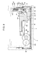
- Fig. 7 shows detailed structure of the swing mechanism 25 and the shutter 6.
- the swing mechanism 25 includes a clamp cam 25A that is reciprocally movable in the direction orthogonal to the advancement and retraction direction of the base plate 3, and two pins 21 A that are formed at the other end of base 21 and guided by cam grooves 250 formed on the clamp cam 25A.
- the clamp cam 25A moves to the left side in Fig. 7 (the right side in Fig. 2) with the recording/reproducing mechanism 2 not being in operation, the other end of the base 21 is lowered.
- the clamp cam 25A moves to the right side in Fig. 7 (the left side in Fig. 2) with the recording/reproducing mechanism 2 being in operation, the other end of the base 21 is raised.
- an operation switching mechanism is provided for switching the advancement and retraction operation of the base plate 3 and the swing operation of the recording/reproducing mechanism 2.
- Each of the cam grooves 250 includes horizontal sections that allow the clamp cam 25A, with the pin 21A being engaged therewith, to move in accordance with the advancement and retraction of the base plate 3 in horizontal direction (the lateral direction in Fig 7), and an inclined section that raises and lowers the recording/reproducing mechanism 2, the horizontal sections being continuously formed on both sides of the inclined section.
- the clamp cam 25A includes a coupling section 25B.
- the coupling section 25B includes a rack portion 25C that meshes with the forth gear 42F and a holding portion 25D that is projected toward the shutter 6. With the forward and reverse rotation of the forth gear 42F, the clamp cam 25A advances and retracts in a direction indicated by an arrow in Fig. 7.
- the coupling section 25B has a hole 25E formed along an operation direction of the switch lever 41 A so that the switch lever 41 A can abut on an edge of the hole 25E.
- the shutter 6 includes a long shutter body 6A that has enough size to cover the slot 1A and a substantially angular C-shaped cross section, and arm sections 6B that are formed by folding both ends of the shutter body 6A, the arm sections 6B defining turning centers.
- the shutter 6 covers the slot 1A when the shutter body 6A is at a raised position, whereas it uncovers the slot 1A when the shutter body 6A is at a lowered position.
- the shutter body 6A and the arm sections 6B are integrally formed of sheet plate.
- the shutter body 6A includes a cam portion 6C that engages with the holding portion 25D for turning the shutter 6 and a holding piece 6D that is adjacent to the cam portion 6C.
- the cam portion 6C is so tilted to raise the shutter body 6A when the clamp cam 25A moves to the right side in Fig. 7 with the recording/reproducing mechanism 2 being in operation, and to lower the shutter body 6A when the clamp cam 25A moves to the left side in Fig. 7 with the recording/reproducing mechanism 2 not being in operation.
- the holding portion 25D includes a turn cam 61 turnably provided as a coupling mechanism.
- the turn cam 61 includes a holding portion 61A formed at an end near the shutter body 6A and an abutment portion 61 B formed at the other end.
- the holding portion 61A abuts on the holding piece 6D and turns.
- the abutment portion 61B knocks down the switch lever 41 A to the right side in Fig. 7, so that the motor 41 of the loading mechanism 4 stops driving.
- the recording/reproducing mechanism 2 starts driving.
- Fig. 8 shows structure of an interlock mechanism 8 that interlocks with the arm unlock mechanism 57.
- the interlock mechanism 8 includes a first gear member 81 having a pin 81A engagable with an end of the slider 57B and a second gear member 82 that meshes with the first gear member 81.
- the second gear member 82 includes an engagement pin 82A engagable with the clamp cam 25A.
- the engagement pin 82A engages with the continuously moving clamp cam 25A and turns the second gear member 82.
- the first gear member 81 turns so that the engagement pin 81 A moves the slider 57B, thereby activating the arm unlock mechanism 57.
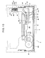
- the loading mechanism 4 is provided with a manual eject mechanism 9 for manually ejecting the hold assembly 5.
- the manual eject mechanism 9 is mainly consisted of a rack-shaped one-way clutch 92 that meshes with a gear portion 42F1 formed to be coaxial with the forth gear 42F and an eject member 93 that advances and retracts the one-way clutch 92.
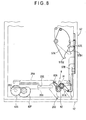
- a cam member 91 as shown in Fig. 9, has a substantially L-shape in plan view, and includes a cam groove 91A inside thereof to engage with a pin-shaped engagement portion 25F projected from the clamp cam 25A.
- the cam member 91 moves to the disk-eject direction as the clamp cam 25A moves to the right side in Fig. 2.
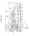
- Fig. 11 shows structure of the one-way clutch 92 and the eject member 93.
- the one-way clutch 92 which has a tilted gear portion, transfers the drive only for moving the clamp cam 25A to a predetermined direction (the right side in Fig. 2), but does not transfer the drive when the one-way clutch 92 moves to the opposite direction.
- the one-way clutch 92 is coupled with the housing 11 and a coil spring 94 at an end so as to always move back to its original position.
- the eject member 93 which is adapted to eject the disk by a plurality of pushing operations, includes a press portion 93A for pressing the end of the one-way clutch 92, a turn portion 93B integrally formed with the press portion 93A, and a pin abutment portion 93C integrally formed with the turn portion 93B for carrying out turning operation with a pin 95.
- the eject member 93 is formed in an appropriate shape, e.g., a lever-shape.
- the base plate 3 moves to the disk-eject direction.
- the turn plate 57A of the arm unlock mechanism 57 turns in counterclockwise direction in Fig. 2 to close the main arms 53 and 54.
- a disk lock mechanism 10 is provided for locking the disk when the eject member 93 is manually pushed.
- a start cam mechanism 45 for starting the rotation of the motor 41 when the base plate 3 advances to a predetermined position.
- the start cam mechanism 45 includes a start cam 46 formed under a slot-side end of the base plate 3, a cam member 91 having an engagement portion 25F that engages with the start cam 46, a base lock 47 formed on the cam member 91, and a clamp cam 25A that engages with the cam member 91.
- the start cam 46 is a thick-plate with a substantially rectangular shape in plan view, and includes a cam groove 46A on its under surface which engages with the engagement portion 25F.
- the cam groove 46A includes a linear groove 46A1 along the advancement and retraction direction of the base plate 3 and an inclined groove 46A2 for moving the engagement portion 25F to the left side in Fig. 9.
- the engagement portion 25F disengages from the linear groove 46A1 to engage with the inclined groove 46A2.
- the clamp cam 25A positioned at the rightmost in Fig. 9 moves to the left side and the switch lever 41A is shifted to start the rotation operation of the motor 41.
- an advancement direction end (the upper end in Fig. 9) of the start cam 46 can be held by a holding projection 91B formed at the end of the cam member 91 whereas a retraction direction end thereof (the lower end in Fig. 9) can be held by the base lock 47.
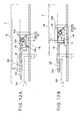
- the base lock 47 includes a base lock body 47B which is turnably formed so that a holding claw 47A for holding an end of the start cam 46 appears from and goes under an upper surface of the cam member 91, and a spring 47C which biases the base lock body 47B so that the holding claw 47A goes under the upper surface of the cam member 91.
- a guide portion 47D is formed at the opposing side of the holding claw 47A on a bottom surface of the base lock body 47B, and guided onto an upper surface of a guide member 11B formed on the housing 11. Accordingly, when the base lock 47 is located at a position shown in Fig. 9, the holding claw 47A stays under the upper surface of the cam member 91 (see Fig. 12A). When the cam member 91 is advanced and located at a position shown in Fig. 10, the guide portion 47D is guided by the guide member 11 B, so that the holding claw 47A proj ects from the upper surface of the cam member 91 to sandwich the start cam 46 with the holding projection 91B (see Fig. 12B).
- the eject arm 52 advances the bridge cam 582 against the biasing force of the spring 583 and the cam face 582B of the bridge cam 582 engages with the cam portion 581A of the bridge plate 581.
- the bridge plate 581 moves to the left side in Fig. 14 against the biasing force of the spring 58A, so that the lock between the holding portion 58B and the holding block 11 A of the housing 11 is released. The release of the lock enables further advancement of the base plate 3.
- the pin body 55A of the eject arm 52 engages with the engagement hole 511. Accordingly, the arm lock mechanism 56 functions, so that the disk D is held by the eject arm 52 and the main arms 53 and 54.
- the base plate 3 to which the arms 52 to 54 are attached, advances. During this advancement, a load required for advancing the base plate 3 is small since the folded sections 32 of the base plate 3 have grooves 32A formed along the advancement and retraction direction of the rack 43.
- the rotation of the motor 41 is transmitted to the rack 43 through the gear mechanism 42, so that the rack 43, the base plate 3 and the hold assembly 5 holding the disk D continue to advance.
- the start cam 46 pushes in the holding projection 91B so that the base plate 3 advances the cam member 91.
- the cam groove 91A of the cam member 91 engages with the engagement portion 25F of the clamp cam 25A to move the clamp cam 25A to the left side, and then the rack portion 25C meshes with the forth gear 42F of the gear mechanism 42.
- the clamp cam 25A continues to move to the left and the cam member 91 also continues to advance.
- the base lock 47 sandwiches the start cam 46 with the holding projection 91B and thus advances it. Therefore, the hold assembly 5 advances even when the mesh between the rack 43 and the gear mechanism 42 is released. Note that the base plate 3 does not move since the base lock 47 and the holding projection 91B sandwich the start cam 46 even when the recording/reproducing mechanism 2 is in operation.
- the clamper hold mechanism 7, as shown in Fig. 16 is activated so that the clamper 70 is disengaged from the holder 7A to face the center of the disk.
- the swing mechanism 25 is activated so that the base portion 21 is raised, then the recording/reproducing mechanism 2 gets into a condition where the reproducing and/or recording is enabled.
- the recording/reproducing mechanism 2 moves closer to a recording/reproducing position, the magnet in the rotary table 22 sticks to the clamper 70 over the disk D to clamp the disk D.
- the main arms 53 and 54 open so that the abutment portions 53B and 54B move away from the disk D.
- the slider 57B engages with the engagement piece 57D1 to turn the turn plate 57A in clockwise direction.
- the selector plate 51 moves to the right side in the drawing to open the main arms 53 and 54.
- the shutter 6 closes the slot 1A.
- the engagement position of the holding portion 25D and the cam portion 6C changes so that the shutter 6 turns to close the slot 1A.
- the turn cam 61 formed on the clamp cam 25A turns in counterclockwise direction in Fig. 17 as the holding portion 61 A thereof abuts on the holding piece 6D.
- the abutment portion 61B shifts the switch lever 41 A so as to send a command for stopping the rotation to the motor 41.
- the clamp cam 25A moves to the right side, thus the recording/reproducing mechanism 2 swings back to its initial position. Then the shutter 6 opens the slot 1A.
- the rack 43 meshes with the seventh gear 42I of the gear mechanism 42.
- the forth gear 42F can not mesh with the rack portion 25C and the clamp cam 25A stops.
- the seventh gear 421 of the gear mechanism 42 meshes with the rack 43, the base plate 3 continues to retract. Note that the rack 43 can move in the advancement and retraction direction because of the grooves 32A formed on the base plate 3, operation stop due to a slip onto the gear is avoided.
- the base plate 3 continues to retract as the seventh gear 421 meshes with the rack 43, and then the clamper hold mechanism 7 is activated so that the holder 7A holds the clamper 70.
- the projection 55E abuts on a projection (not shown) formed on the housing 11 and the cam member 55D stops.
- the tip end of the engagement pin 55 moves along the cam face of the cam member 55D so that the pin body 55A is disengaged from the engagement hole 511. Then the arm member 52D pushes out the disk D with the eject arm 52 toward the slot with the biasing force of the spring 52E.
- the base plate 3 moves back to the initial position.
- the start cam 46 moves the clamp cam 25A to the right side, so that the switch lever 41 A is shifted to stop the rotation of the motor 41.
- the coil spring 5A of the selector plate 51 biases the main arms 53 and 54 to their closing direction. Therefore, the selector plate 51 moves to the left side. Since the engagement recess 51E, which is formed on the selector plate 51, has its right side defining an inclined surface, the tip end of the engagement pin 55 passes thought the inclined surface and the eject arm 52 moves toward the slot 1A. Thus, the eject arm 52 and the main arms 53 and 54 move back to the positions where they are located before the insertion of the disk D.
- the user pushes the small disk D onto the main arms 53 and 54 to open them and pushes it onto the eject arm 52.
- the eject arm 52 advances the bridge cam 582.
- the cam face 582A of the bridge cam 582 engages with the cam portion 581A of the bridge plate 581.
- the lock between the holding portion 58B and the holding block 11 A of the housing 11 is released.
- the pin body 55A of the eject arm 52 engages with the engagement hole 512, so that the small disk D is held by the eject arm 52 and the main arms 53 and 54.
- the main arms 53 and 54 open so that the abutment portions 53B and 54B move away from the small disk D.
- the slider 57B engages with the engagement piece 57D2 to turn the turn plate 57A in clockwise direction.
- Steps after ending of the drive of the recording/reproducing mechanism 2 are the same as those for the large disk D.
- the engagement pin 55 attached to the eject arm 52 enters the engagement recess 51F to abut on a lateral wall of the recess and gets held therein.
- two types of disk D with different sizes are applied.
- three or more types of disk D with different sizes or equally sized disks can be applied.
- engagement recesses are formed depending on the number of the types of the disk D.
- the position of the cam is determined in accordance with the type of the disk D.
- the eject arm 52 and the main arms 53 and 54 are respectively biased with springs, elastic members such as rubber may be used instead of the springs.
- the eject arm 52 is formed in a substantially U-shape having two abutment portions 52B at the tip ends thereof, the eject arm is not necessarily to be in the substantially U-shape and it may have only one abutment portion in the present invention. However, the disk D will more surely goes straight when two abutment portions 52B are provided.
- the grooves 32A for allowing the relative movement of the rack 43 and the base plate 3 may be provided on the rack 43. Though the two grooves 32A are formed in line along the advancement and retraction direction of the base plate 3, the number of the groove 32A may be one. However, the rack 43 can more surely go straight when two grooves 32A are provided as in the above embodiment.
- the switch lever 41 A performs switching operation at three positions, i.e., the center position for turning the motor 41 and the both left and right side positions for stopping the turn
- the switch lever 41A for performing it at two positions may be applicable in this invention.
- such two-position switch may be used in pairs or singularly used.
Landscapes
- Feeding And Guiding Record Carriers (AREA)
Applications Claiming Priority (2)
| Application Number | Priority Date | Filing Date | Title |
|---|---|---|---|
| JP2003035696A JP3959356B2 (ja) | 2003-02-13 | 2003-02-13 | スロットイン型再生記録装置 |
| JP2003035696 | 2003-02-13 |
Publications (2)
| Publication Number | Publication Date |
|---|---|
| EP1447801A2 true EP1447801A2 (fr) | 2004-08-18 |
| EP1447801A3 EP1447801A3 (fr) | 2005-05-25 |
Family
ID=32677616
Family Applications (1)
| Application Number | Title | Priority Date | Filing Date |
|---|---|---|---|
| EP04250731A Withdrawn EP1447801A3 (fr) | 2003-02-13 | 2004-02-11 | Appareil d' enregistrement/lecture du type à encartement |
Country Status (4)
| Country | Link |
|---|---|
| US (1) | US7117509B2 (fr) |
| EP (1) | EP1447801A3 (fr) |
| JP (1) | JP3959356B2 (fr) |
| CN (1) | CN1542807A (fr) |
Families Citing this family (10)
| Publication number | Priority date | Publication date | Assignee | Title |
|---|---|---|---|---|
| JP4096817B2 (ja) * | 2003-06-06 | 2008-06-04 | 日本ビクター株式会社 | ディスクドライブ装置 |
| JP4103742B2 (ja) * | 2003-09-11 | 2008-06-18 | ソニー株式会社 | ディスクドライブ装置 |
| JP2005122866A (ja) * | 2003-10-20 | 2005-05-12 | Pioneer Electronic Corp | ディスク搬送装置 |
| KR100598050B1 (ko) * | 2004-07-29 | 2006-07-10 | 삼성전자주식회사 | 디스크 로딩장치 및 디스크 로딩방법 |
| KR20060014610A (ko) * | 2004-08-11 | 2006-02-16 | 삼성전자주식회사 | 디스크 이격장치 및 이를 포함한 디스크 플레이어 |
| CN2763937Y (zh) * | 2004-11-12 | 2006-03-08 | 鸿富锦精密工业(深圳)有限公司 | 光盘播放器 |
| JP2007035140A (ja) * | 2005-07-26 | 2007-02-08 | Funai Electric Co Ltd | ディスクローディング装置 |
| WO2007108255A1 (fr) * | 2006-03-15 | 2007-09-27 | Clarion Co., Ltd. | Lecteur de disques |
| JP2011108332A (ja) * | 2009-11-18 | 2011-06-02 | Sharp Corp | ディスク装置 |
| JP2011238318A (ja) * | 2010-05-12 | 2011-11-24 | Pioneer Digital Design And Manufacturing Corp | ディスク装置 |
Family Cites Families (9)
| Publication number | Priority date | Publication date | Assignee | Title |
|---|---|---|---|---|
| CA1204859A (fr) * | 1982-12-12 | 1986-05-20 | Nobuyuki Hara | Chargeur de disques |
| US4695996A (en) | 1984-04-11 | 1987-09-22 | Pioneer Electronic Corporation | Automatic loading disc player |
| JP3021442B2 (ja) * | 1997-12-31 | 2000-03-15 | 三星電子株式会社 | ディスクプレ―ヤ― |
| EP1035541B1 (fr) | 1998-09-29 | 2006-01-18 | Mitsubishi Denki Kabushiki Kaisha | Dispositif pour disque |
| JP4486238B2 (ja) * | 2000-09-14 | 2010-06-23 | パナソニック株式会社 | 光ディスク装置 |
| TW517228B (en) | 2000-10-13 | 2003-01-11 | Teac Corp | Loading device for recording medium |
| CN100397518C (zh) * | 2001-04-27 | 2008-06-25 | 松下电器产业株式会社 | 盘装置 |
| JP4103742B2 (ja) * | 2003-09-11 | 2008-06-18 | ソニー株式会社 | ディスクドライブ装置 |
| US20050198656A1 (en) * | 2003-12-05 | 2005-09-08 | Sony Corporation | Disc drive device |
-
2003
- 2003-02-13 JP JP2003035696A patent/JP3959356B2/ja not_active Expired - Fee Related
-
2004
- 2004-02-11 US US10/775,186 patent/US7117509B2/en not_active Expired - Fee Related
- 2004-02-11 EP EP04250731A patent/EP1447801A3/fr not_active Withdrawn
- 2004-02-13 CN CNA2004100053842A patent/CN1542807A/zh active Pending
Non-Patent Citations (1)
| Title |
|---|
| None * |
Also Published As
| Publication number | Publication date |
|---|---|
| US7117509B2 (en) | 2006-10-03 |
| JP2004246969A (ja) | 2004-09-02 |
| CN1542807A (zh) | 2004-11-03 |
| JP3959356B2 (ja) | 2007-08-15 |
| EP1447801A3 (fr) | 2005-05-25 |
| US20040163092A1 (en) | 2004-08-19 |
Similar Documents
| Publication | Publication Date | Title |
|---|---|---|
| EP1447801A2 (fr) | Appareil d'enregistrement/lecture du type à encartement | |
| EP1447803A2 (fr) | Dispositif d'enregistrement et de lecture du type à fente. | |
| EP1447802A2 (fr) | Dispositif d'enregistrement et de lecture | |
| JP3867692B2 (ja) | ディスク記録及び/又は再生装置 | |
| JP3901138B2 (ja) | 再生装置 | |
| JP3902533B2 (ja) | 記録媒体のローディング装置 | |
| KR100258232B1 (ko) | 디스크장치 | |
| JP3900120B2 (ja) | ディスク再生装置 | |
| JP4232736B2 (ja) | スロットイン型ディスク装置 | |
| JPH0650851Y2 (ja) | テ−プカセットロ−ディング装置 | |
| JP2630881B2 (ja) | ディスクのローディング装置 | |
| JP2005044444A (ja) | ディスク記録及び/又は再生装置 | |
| JP4412088B2 (ja) | ディスクカートリッジのローディング装置 | |
| JP3941754B2 (ja) | 再生装置 | |
| JPS58166571A (ja) | カセツト装着装置 | |
| JPH0454587Y2 (fr) | ||
| JP2520080B2 (ja) | フロッピ―ディスク装置 | |
| JPH03283047A (ja) | ディスクドライブ | |
| JP2671579B2 (ja) | カセット装着装置 | |
| JPH10188421A (ja) | ディスク装置 | |
| JPH04268245A (ja) | ディスクドライブのリストレイン解除機構 | |
| JPH05135470A (ja) | デイスクドライブ | |
| JPH0789420B2 (ja) | テ−プレコ−ダにおけるテ−プカセツトロ−デイング装置 | |
| JP2000021061A (ja) | 記録再生装置 | |
| JPH07130066A (ja) | ディスク装置 |
Legal Events
| Date | Code | Title | Description |
|---|---|---|---|
| PUAI | Public reference made under article 153(3) epc to a published international application that has entered the european phase |
Free format text: ORIGINAL CODE: 0009012 |
|
| AK | Designated contracting states |
Kind code of ref document: A2 Designated state(s): AT BE BG CH CY CZ DE DK EE ES FI FR GB GR HU IE IT LI LU MC NL PT RO SE SI SK TR |
|
| AX | Request for extension of the european patent |
Extension state: AL HR LT LV MK |
|
| RIN1 | Information on inventor provided before grant (corrected) |
Inventor name: KIKUCHI, KENJI,C/O PIONEER CORPORATION Inventor name: KONNO, YOUICHI,C/O PIONEER CORPORATION Inventor name: OOIZUMI, KENJIROU,C/O PIONEER CORPORATION Inventor name: MAKISAKA, YUKINARI,C/O PIONEER CORPORATION |
|
| PUAL | Search report despatched |
Free format text: ORIGINAL CODE: 0009013 |
|
| AK | Designated contracting states |
Kind code of ref document: A3 Designated state(s): AT BE BG CH CY CZ DE DK EE ES FI FR GB GR HU IE IT LI LU MC NL PT RO SE SI SK TR |
|
| AX | Request for extension of the european patent |
Extension state: AL HR LT LV MK |
|
| 17P | Request for examination filed |
Effective date: 20051115 |
|
| AKX | Designation fees paid |
Designated state(s): DE FR GB |
|
| 17Q | First examination report despatched |
Effective date: 20061024 |
|
| STAA | Information on the status of an ep patent application or granted ep patent |
Free format text: STATUS: THE APPLICATION IS DEEMED TO BE WITHDRAWN |
|
| 18D | Application deemed to be withdrawn |
Effective date: 20070306 |