EP1448329B1 - Dispositif et procede de coulee en continu - Google Patents
Dispositif et procede de coulee en continu Download PDFInfo
- Publication number
- EP1448329B1 EP1448329B1 EP02773100A EP02773100A EP1448329B1 EP 1448329 B1 EP1448329 B1 EP 1448329B1 EP 02773100 A EP02773100 A EP 02773100A EP 02773100 A EP02773100 A EP 02773100A EP 1448329 B1 EP1448329 B1 EP 1448329B1
- Authority
- EP
- European Patent Office
- Prior art keywords
- casting
- magnetic field
- melt
- casting mould
- molten metal
- Prior art date
- Legal status (The legal status is an assumption and is not a legal conclusion. Google has not performed a legal analysis and makes no representation as to the accuracy of the status listed.)
- Expired - Lifetime
Links
- 238000009749 continuous casting Methods 0.000 title claims abstract description 12
- 238000000034 method Methods 0.000 title claims description 28
- 238000005266 casting Methods 0.000 claims abstract description 214
- 239000002184 metal Substances 0.000 claims abstract description 59
- 229910052751 metal Inorganic materials 0.000 claims abstract description 59
- 238000004590 computer program Methods 0.000 claims abstract description 11
- 150000002739 metals Chemical class 0.000 claims abstract description 10
- 239000000155 melt Substances 0.000 claims description 55
- 238000004804 winding Methods 0.000 claims description 23
- 239000012768 molten material Substances 0.000 claims description 20
- 238000003756 stirring Methods 0.000 claims description 12
- 239000004020 conductor Substances 0.000 claims description 8
- 230000001419 dependent effect Effects 0.000 claims description 8
- 230000003247 decreasing effect Effects 0.000 claims 4
- 230000000694 effects Effects 0.000 description 6
- 230000005499 meniscus Effects 0.000 description 5
- 239000000463 material Substances 0.000 description 4
- 230000008859 change Effects 0.000 description 3
- 239000002893 slag Substances 0.000 description 3
- 238000007711 solidification Methods 0.000 description 3
- 230000008023 solidification Effects 0.000 description 3
- XKRFYHLGVUSROY-UHFFFAOYSA-N Argon Chemical compound [Ar] XKRFYHLGVUSROY-UHFFFAOYSA-N 0.000 description 2
- 230000004907 flux Effects 0.000 description 2
- 239000007789 gas Substances 0.000 description 2
- 230000001788 irregular Effects 0.000 description 2
- 230000010355 oscillation Effects 0.000 description 2
- RYGMFSIKBFXOCR-UHFFFAOYSA-N Copper Chemical compound [Cu] RYGMFSIKBFXOCR-UHFFFAOYSA-N 0.000 description 1
- XEEYBQQBJWHFJM-UHFFFAOYSA-N Iron Chemical group [Fe] XEEYBQQBJWHFJM-UHFFFAOYSA-N 0.000 description 1
- 230000001133 acceleration Effects 0.000 description 1
- 239000000956 alloy Substances 0.000 description 1
- 229910045601 alloy Inorganic materials 0.000 description 1
- 229910052786 argon Inorganic materials 0.000 description 1
- 230000015572 biosynthetic process Effects 0.000 description 1
- 238000009529 body temperature measurement Methods 0.000 description 1
- 238000001816 cooling Methods 0.000 description 1
- 229910052802 copper Inorganic materials 0.000 description 1
- 239000010949 copper Substances 0.000 description 1
- 239000012943 hotmelt Substances 0.000 description 1
- 239000012535 impurity Substances 0.000 description 1
- 238000005259 measurement Methods 0.000 description 1
- 238000012986 modification Methods 0.000 description 1
- 230000004048 modification Effects 0.000 description 1
- 230000000737 periodic effect Effects 0.000 description 1
Images

Classifications
-
- B—PERFORMING OPERATIONS; TRANSPORTING
- B22—CASTING; POWDER METALLURGY
- B22D—CASTING OF METALS; CASTING OF OTHER SUBSTANCES BY THE SAME PROCESSES OR DEVICES
- B22D11/00—Continuous casting of metals, i.e. casting in indefinite lengths
- B22D11/10—Supplying or treating molten metal
- B22D11/11—Treating the molten metal
- B22D11/114—Treating the molten metal by using agitating or vibrating means
- B22D11/115—Treating the molten metal by using agitating or vibrating means by using magnetic fields
Definitions
- the present invention relates to a method and an apparatus for continuous casting of metals, comprising a casting mould with an elongated horizontal cross section, through which a molten metal is intended to pass during the casting operation, a member for supplying a molten metal to such molten metal already present in the casting mould in a region at a distance below the upper surface of the latter melt, and a device adapted to apply magnetic fields to the melt in the casting mould to influence movements of the molten material.
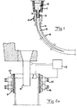
- a molten metal 2 is supplied to a casting mould 3 in the form of a box, open at the top and at the bottom, having cooled walls, usually of a copper-based alloy with a good thermal conductivity.
- the cooling in the casting mould causes the solidification of the elongated strand, formed by the molten metal, to begin from the outside and proceed inwards towards the centre of the strand.
- a strand is formed which is usually referred to as a slab.
- the cooled and partially solidified strand continuously leaves the casting mould.
- the strand leaves the casting mould, it has at least one mechanically self-supporting, solidified casing 4 that surrounds a non-solidified centre 5. It is shown schematically how it is sufficient with guide rollers S to guide and support the strand downstream of the casting mould.
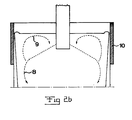
- the primary flow 8 extends downwards in the casting direction, whereas the secondary flow 9 extends from the area of the walls 10 of the casting mould upwards towards the upper surface of the molten bath and then downwards.
- periodic velocity fluctuations arise in the cast material during the casting process. These fluctuations are also due to the walls of the casting mould being normally set into an oscillating movement to prevent solidified cast material from adhering thereto.
- the irregular movements caused thereby in the molten metal implies, inter alia, that bubbles, for example argon gas bubbles, and impurities in the melt, for example oxide inclusions from the casting pipe and slags from the meniscus, are transported far down in the casting direction, that is, far down in the cast strand that is initially formed in the casting mould. This results in inclusions and irregularities of the finished, solidified cast strand.
- bubbles for example argon gas bubbles
- impurities in the melt for example oxide inclusions from the casting pipe and slags from the meniscus
- a device as mentioned above is arranged to apply magnetic fields to the melt in the casting mould.
- EMBR ElectroMagnetic BRake
- a stationary magnetic field that is, a magnetic field generated by leading a direct current through a coil of an electromagnet, is applied to the melt in the casting mould from one long side to the other. This then results in the movements of the molten material being braked.
- such electromagnets may be arranged along the casting mould in the vicinity of, or below, the region for the supply of molten metal in order thus to brake the flow of the molten metal downwards in the casting mould, that is, substantially to influence the primary flow mentioned, to try to render the speed of this movement essentially constant over the whole cross section of the casting mould, and to stabilize the upwardly-directed secondary flow at the short sides of the casting mould.
- a so-called brake in the area of the upper surface of the casting mould to brake the movements of the molten metal in this area and remove surface oscillations in the melt.
- FC Flow Control
- EMS Electromagnetic Stirring
- the object of the present invention is to provide an apparatus and a method which make it possible to obtain, at least under certain casting conditions, a casting result which, at least in certain respects, is improved in relation to what is possible to achieve with prior art apparatuses and methods for continuous casting of metals.
- the device exhibits members adapted to generate a stationary magnetic field with a variable strength over essentially the whole of said cross-section of the casting mould from one long side to the other long side in the vicinity of, or below, the region for said supply of the molten metal, and members adapted to generate a variable magnetic field in the area of said upper surface in a region that is centrally located with respect to said cross section and close to said region for supply of melt, and, in addition, the apparatus exhibits a unit adapted to control the magnetic members of the device to generate, independently of each other, magnetic fields with an appearance that is dependent on the value prevailing of one or more predetermined casting parameters.
- a flow rate of the melt in various parts of the casting mould which is optimal for a uniform, stable temperature of the upper surface of the melt may to a large extent be achieved under changing casting conditions, primarily casting speed.
- variable magnetic field comprises also magnetic fields of so-called alternating type, that is, where the magnetic field is generated by an electromagnet supplied with an alternating current.
- alternating type that is, where the magnetic field is generated by an electromagnet supplied with an alternating current.
- a braking of the downward movement of the melt may be performed by means of the first-mentioned magnetic member, which permits the above-mentioned bubbles to rise to the upper surface and be removed and not be incorporated in the solidified portion of the strand, while at the same time the secondary flow upwards at the short ends of the strand may be stabilized for stable supply of hot melt to the meniscus and energy addition thereto.
- the last-mentioned magnetic member adapted to generate a variable magnetic field can ensure that the movements of the melt in the area of the upper surface thereof, especially in said central region, are the most suitable movements at a value prevailing of one or more of said predetermined casting parameters, for achieving, over the whole cross section of the casting mould, an essentially uniform speed of the melt at the upper surface and hence a uniform, stable temperature of the upper surface of the melt.
- the apparatus exhibits a device with members adapted to generate a stationary magnetic field with a variable strength in the area of said upper surface in the end regions of the casting mould which, with respect to said cross section, are located externally of and remotely from the above-mentioned region for supply of melt, and the apparatus further comprises a unit adapted to control said outer magnetic member to generate a magnetic field with a strength that is dependent on the value prevailing of one or more predetermined casting parameters.
- movements of the molten material in the area of said upper surface may be braked in said end regions to an extent that is optimal for the prevailing conditions on each individual casting occasion, that is, the value prevailing of one or more predetermined casting parameters.
- the apparatus according to the invention comprises both kinds of said magnetic members. This then leads to possibilities of achieving a flow rate of the melt in various parts of the casting mould which is optimal for the casting result, both deeper downwards in the casting mould and upwards in the casting mould, and in the area of the upper surface, as well as a uniform, stable temperature and movement of the upper surface of the melt irrespective of the casting speeds occurring.
- an excellent casting result may be obtained at low casting speeds, when the melt in the area of the upper surface needs to be stirred, above all near the casting pipe, and be accelerated, at casting speeds in an intermediate range, when hot molten material needs to be supplied to the area of the upper surface from the casting jet, stirring in the area of the upper surface around the casting pipe is needed and the movements of the melt in the area of the upper surface must be braked somewhat to obtain a maximum flow rate in the upper surface, and at high casting speeds, when the braking of the upper surface must be strong to achieve an optimum speed of the melt in the area of the upper surface, while at the same time no stagnation zones are allowed to arise centrally around the casting pipe.
- said magnetic members for generating a magnetic field in said central region comprise at least two magnetic cores, arranged at each long side of the casting mould, with electric conductor windings connected to different phases of a source for generating a polyphase ac voltage for achieving a magnetic field that travels in said central region in the upper surface of the melt in a direction towards the long side of the casting mould, which makes possible stirring and acceleration of the movement of the molten material in this central region of the upper surface of the melt when this is needed.
- the apparatus comprises means for varying the frequency of the current through the windings of the magnetic member for generating the magnetic field in said central region of the casting mould, and the unit is adapted to control said means in dependence on the value prevailing of one or more predetermined casting parameters.
- the molten material may in the central region be influenced into a movement which is the most optimal one for the particular casting conditions prevailing, and according to a further preferred embodiment of the invention, said means has the ability to control said frequency down to 0 Hz, which means that a direct current is then fed through the windings and a stationary magnetic field is generated in the area of the upper surface in said central region of the casting mould, such that these magnetic members then exert a braking effect on movements in this central region, which is suitable for high casting speeds.
- said strength of this braking effect is then controlled according to the casting speed and any other casting parameters so that an optimum movement of the molten material in this region occurs and no stagnation zones are formed in this area.
- said means is a converter of a kind known per se.
- the apparatus comprises members adapted to measure the temperature of the melt in the casting mould near said upper surface and to send information about this to the unit as a said predetermined casting parameter, members adapted to measure the casting speed, that is, how large a volume of melt that is supplied to the casting mould per unit of time, and to send information about this to the unit as a said predetermined casting parameter, and/or members adapted to measure the level of said upper surface of the melt in the casting mould and to send information about this to the unit as a said predetermined casting parameter. Since the unit takes into consideration different such casting parameters in its control of the magnetic members, in each given situation the molten material in the casting mould may be influenced to achieve an optimum casting result.
- the invention also includes the case where the unit is adapted to control one or more said magnetic members occasionally not to generate any magnetic field.
- any of the magnetic members could be completely shut off at a value of any casting parameter, such as casting speed, within a predetermined range of values.
- the unit is adapted, at determined values of one or more of said predetermined casting parameters, to control said members for generating a magnetic field in the area of the upper surface in said central region to alternately generate a so-called alternating field, changing in time, for stirring the molten metal and a stationary magnetic field for braking the movements of the molten metal.
- a very good temperature equalization of the melt in the area of the upper surface of the molten bath may be obtained.
- the unit is advantageously adapted to control said magnetic members in dependence on the value prevailing of one or more predetermined casting parameters according to an algorithm for the purpose of achieving a flow rate of the melt in different parts of the casting mould which is optimal for the casting result, and a uniform, stable temperature of the upper surface of the melt.
- the invention also relates to methods for continuous casting of metals according to the appended independent method claims. How these methods function and the advantages thereof should be manifestly clear from the above discussion of the apparatuses according to the invention.
- the invention also relates to a computer program, a computer program product and a computer-readable medium according to the corresponding appended claims. It is readily realized that the method according to the invention defined in the appended set of method claims is well suited to be carried out by program instructions from a processor controllable by a computer program provided with the program steps in question. Further advantages and advantageous features of the invention will be clear from the following description and the other dependent claims.
- the casting mould 3 has an elongated horizontal cross section, and in practice this normally means a considerably smaller relation of length of the short side to length of the long side than what is shown in the figures, and in this respect the figures are only to be interpreted as explaining the principles of the invention.
- the thickness of the strand may, for example, be of the order of magnitude of 150 mm while at the same time its width is over 1,500 mm.
- the molten metal that is supplied to the casting mould has a certain overtemperature, that is, the temperature thereof must be lowered to a certain extent in order for any part thereof to start solidifying. This is important in order to avoid that solidification of the molten metal begins too early, for example in the area of its upper surface. To avoid such solidification, it is also necessary that the melt should exhibit a certain movement in all regions, cross section-wise both centrally and at the ends, such that an equalization of the temperature of the upper surface may occur. In Figure 3, it is shown how the melt typically flows in said secondary flow 9 in the upper surface.
- the primary flow 8 downwards of the melt be essentially constant over the whole horizontal cross section of the casting mould, so that bubbles and the like formed therein have a possibility of moving upwards to the upper surface 7 and disappearing and are not drawn along in some part that moves considerably faster than any other part.
- the apparatus exhibits magnetic members and a unit 12 adapted to control these members independently of each other in dependence on the value prevailing of one or more predetermined casting parameters.
- the magnetic members are schematically indicated electromagnets in the form of magnetic cores 13, preferably laminated iron cores, and electric conductor windings wound around these, which are schematically represented here.
- the unit 12 is adapted to control sources 15, 15', 15", connected to the different windings, for electrical energy to feed the windings with electric current and thereby generate magnetic fields extending from one long side to another in the casting mould through the melt.
- the apparatus thus exhibits first magnetic members 16 adapted to generate a stationary magnetic field with a variable strength across essentially the whole horizontal cross section of the casting mould from one long side to the other long side in the vicinity of, or below, the region for supply of the molten metal to the casting mould.
- the unit 12 controls the source 15" to feed the windings of the magnetic member 16 with direct current of a variable strength to generate a magnetic field that exerts a braking effect on the movement of the melt downwards in the casting mould and the upwardly-directed flow at the short sides of the casting mould.
- the apparatus also exhibits second magnetic members 17, also these being in the form of electromagnets, which are adapted to generate a variable magnetic field in the area of said upper surface in a region that is centrally located with respect to said cross section and close to said region for supply of melt.
- second magnetic members 17 also these being in the form of electromagnets, which are adapted to generate a variable magnetic field in the area of said upper surface in a region that is centrally located with respect to said cross section and close to said region for supply of melt.
- second magnetic members 17 also these being in the form of electromagnets, which are adapted to generate a variable magnetic field in the area of said upper surface in a region that is centrally located with respect to said cross section and close to said region for supply of melt.
- three coils are arranged, each being connected to a respective phase of a three-phase ac voltage.
- the apparatus exhibits schematically indicated means 18 adapted to convert the ac voltage from the current source 15' to set the frequency thereof, whereby the converter may preferably vary
- the apparatus exhibits third magnetic members 19, which are also of the electromagnet type and adapted to generate a stationary magnetic field with a variable strength in the area of said upper surface in those end regions of the casting mould which, with respect to said cross section, are located externally of and remotely from the region for supply of the melt. In this way, where necessary, the movements of the melt in the area of the upper surface may be braked in these end regions, but it is also possible to disconnect this magnetic member when no such braking is desired.
- the apparatus exhibits members for measuring certain parameters that are important for the casting and sending information about this to the unit 12, so that this unit can then control the different magnetic members in dependence on this information.
- a member 20 adapted to measure the temperature of the melt in the casting mould in an indirect manner by measuring the temperature of the wall of the casting mould.
- This temperature measurement may be performed continuously or intermittently at one or more points. It is then of special interest to measure the temperature in the area of the meniscus.
- the unit 12 preferably exhibits a processor capable of being influenced by a computer program for suitable control of the various magnetic members to achieve an optimum casting result.
- the second magnetic member 17 is preferably controlled to generate a travelling field with a relatively high strength to achieve such a stirring.
- the third magnetic members 19 could be almost or completely disconnected, whereas a certain degree of braking of the flows upwards and downwards in the molten metal through the first magnetic member 16 is desirable. In the upper surface this may result in the flow configuration according to Figure 3 with a controlled or uncontrolled flow A and a stirred flow B.
- the strength of the travelling field generated by the second magnetic member in the central region may be somewhat reduced, while at the same time the third magnetic members 19 are controlled to generate a stationary field that brakes the upper surface somewhat at the end regions.
- the second magnetic member 17 is advantageously controlled to generate a stationary, braking magnetic field in the central region of the upper surface, but the magnetic members 19 are controlled such that the braking effect is greater at the end regions to achieve a uniform speed of the molten material along the whole upper surface.
- the combination of the three magnetic members of the apparatus according to Figure 4 and the possibility of separate control thereof provided by the unit 12 contribute to achieve a flow rate of the melt in various parts of the casting mould which is optimal for the casting result, and to achieve a uniform, stable temperature of the upper surface of the melt at low and high casting speeds as well as casting speeds in the intermediate range.
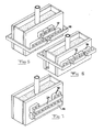
- FIG 5 illustrates schematically how an apparatus according to the invention could be provided with only first 16 and second 17 magnetic members, which makes this apparatus suited especially for lower casting speeds. It is pointed out that in this embodiment and the embodiments according to Figures 6 and 7, electromagnets are arranged along both long sides of the casting mould and these are supplied and controlled in a manner corresponding to that shown for the embodiment according to Figure 4, although this is not shown in these figures for reasons of simplification.
- Figure 6 illustrates an apparatus according to an embodiment that only exhibits said second 17 and third 19 magnetic members.
- the magnetic field generated by the third magnetic member 19 in an end region is closed by a yoke 23 interconnecting the electrodes
- Figure 7 shows the two electromagnets, belonging to the magnetic member 19 and arranged on the same long side, are arranged with their poles in such a way that the magnetic field is closed by a yoke 24 interconnecting these.
- the embodiment shown in Figure 7 with only first and third magnetic members 16 and 19, respectively, constitutes a simplified variant of the apparatus according to the invention, especially suited for higher casting speeds.
- the various magnetic members could have a different extent in the cross section of the casting mould to that shown in the figures, and, for example, in the embodiment according to Figure 5, the second magnetic member could extend a longer distance along the respective long side, possibly to the respective short side, depending on the casting process that is to be controlled.
- the number of phases could be different from three, for example two.
- the different magnetic fluxes could be closed in largely arbitrary ways.
- the magnetic flux from the magnetic members at the end regions of the upper surface could be closed via the first magnetic members located at a deeper level.
Landscapes
- Engineering & Computer Science (AREA)
- Mechanical Engineering (AREA)
- Continuous Casting (AREA)
- Separation By Low-Temperature Treatments (AREA)
Claims (34)
- Dispositif de coulée en continu de métaux, comprenant : une lingotière (3) de coulée ayant une section transversale horizontale oblongue, dans laquelle un métal fondu est destiné à passer au cours de l'opération de coulée, un élément (6) pour fournir un métal fondu au métal fondu déjà présent dans la lingotière, dans une région à une distance au-dessous de la surface supérieure de ce dernier, et un dispositif (13 à 19) conçu pour appliquer des champs magnétiques au métal fondu dans la lingotière afin d'exercer une influence sur des mouvements du métal fondu,
dans lequel le dispositif comporte des éléments (16) conçus pour engendrer un champ magnétique stationnaire d'une intensité variable, dans sensiblement toute la section transversale de la lingotière, d'un grand côté à l'autre, au voisinage ou au-dessous de la région d'alimentation en métal fondu, et des éléments (17) conçus pour engendrer un champ magnétique variable sur l'aire de la surface supérieure dans une région qui est au centre par rapport à la section transversale et à proximité de la région d'alimentation en métal fondu, et le dispositif comprenant une unité (12) conçue pour commander les éléments magnétiques du dispositif pour qu'ils engendrent, indépendamment les uns des autres, des champs magnétiques dont l'aspect est fonction de la valeur d'un ou de plusieurs paramètre(s) de coulée déterminé(s) à l'avance,
caractérisé en ce que les éléments (16, 17) magnétiques comprennent des noyaux (13) magnétiques et des courants (14) de conducteurs électriques passés autour de ceux-ci, en ce que le dispositif comprend une ou plusieurs source(s) (15, 15', 15") pour alimenter ces courants en courant électrique, en ce que l'unité (12) est conçue pour commander l'alimentation en courant des courants, en fonction de la valeur d'un ou de plusieurs paramètre(s) de coulée déterminé(s) à l'avance, l'élément (17) magnétique pour engendrer un champ magnétique dans la région centrale comprenant au moins deux noyaux magnétiques disposés le long de chaque grand côté de la lingotière, des courants de conducteurs électriques étant connectés à différentes phases d'une source pour engendrer une tension alternative polyphasée, afin d'obtenir un champ magnétique qui se propage dans la région centrale de la surface supérieure du métal fondu, dans la direction du grand côté de la lingotière et le dispositif comprenant un moyen (18) destiné à faire varier la fréquence du courant dans les courants de l'élément (17) magnétique pour engendrer le champ magnétique dans la région centrale de la lingotière, et l'unité étant conçue pour commander le moyen, en fonction de la valeur d'un ou de plusieurs paramètre(s) de coulée déterminé(s) à l'avance, le moyen (18) étant apte à réguler la fréquence en l'abaissant à 0 Hz, afin qu'un courant continu passe dans les courants et qu'un champ magnétique stationnaire soit engendré dans l'aire de la surface supérieure de la région centrale de la lingotière, et l'unité étant conçue, à des valeurs spécifiées d'un ou de plusieurs des paramètres de coulée déterminés à l'avance, pour commander l'élément (17) pour qu'il engendre un champ magnétique dans l'aire de la surface supérieure des régions centrales, afin d'engendrer en alternance un champ dit alternatif, variable dans le temps, pour brasser le métal fondu et un champ magnétique stationnaire pour freiner les mouvements du métal fondu. - Dispositif suivant la revendication 1, caractérisé en ce que le dispositif comporte en outre, des éléments (19) conçus pour engendrer un champ magnétique stationnaire d'une intensité variable dans l'aire de la surface supérieure des régions d'extrémité de la lingotière qui, par rapport à la section transversale, sont à l'extérieur et à distance de la région mentionnée ci-dessus d'alimentation en métal fondu, en ce que le dispositif comprend une unité (12) conçue pour commander les éléments magnétiques extérieurs pour qu'ils engendrent un champ magnétique d'une intensité qui est fonction de la valeur d'un ou de plusieurs paramètre(s) de coulée déterminé(s) à l'avance, en ce que, en outre, les éléments (19) magnétiques pour engendrer un champ magnétique dans les régions d'extrémité comprennent des noyaux magnétiques et des courants de conducteurs électriques passés autour de ceux-ci, en ce que les sources sont agencées pour alimenter les courants en courant électrique, et en ce que l'unité (12) est conçue pour commander l'alimentation en courant des courants, en fonction de la valeur d'un ou de plusieurs paramètre(s) de coulée déterminé (s) à l'avance.
- Dispositif suivant la revendication 1 ou 2,
caractérisé en ce que l'élément (17) magnétique pour engendrer un champ magnétique dans la région centrale de la surface supérieure, s'étend sensiblement sur toute la section transversale de la lingotière, d'un petit côté à l'autre, afin d'engendrer des champs magnétiques dans l'aire de la surface supérieure, sensiblement sur la totalité de la section transversale horizontale. - Dispositif suivant la revendication 1 ou 2,
caractérisé en ce que l'élément (17) magnétique, pour engendrer un champ magnétique dans la région centrale de la lingotière, comprend au moins trois noyaux magnétiques ayant des courants de conducteurs électriques, et en ce qu'ils sont conçus pour être connectés à une tension alternative triphasée. - Dispositif suivant la revendication 1 ou 2,
caractérisé en ce que le moyen (18) est constitué d'un convertisseur de courant continu en courant alternatif ou de courant alternatif en courant continu. - Dispositif suivant la revendication 1 ou 2,
caractérisé en ce qu'il comprend des éléments (20) conçus pour mesurer la température du métal fondu dans la lingotière, au voisinage de la surface supérieure, et pour envoyer des informations à ce sujet, à l'unité, en tant que paramètre de coulée déterminé à l'avance. - Dispositif suivant la revendication 6, caractérisé en ce que l'élément (20) de mesure de la température est conçu pour mesurer la température du métal fondu indirectement, en détectant la température d'une paroi de la lingotière.
- Dispositif suivant la revendication 1 ou 2,
caractérisé en ce qu'il comprend des éléments (21) conçus pour mesurer la vitesse de coulée, c'est-à-dire la valeur d'un volume du métal fondu qui est fourni à la lingotière par unité de temps, et pour envoyer des informations à ce sujet, à l'unité, en tant que paramètre de coulée déterminé à l'avance. - Dispositif suivant la revendication 1 ou 2,
caractérisé en ce qu'il comprend des éléments (22) conçus pour mesurer le niveau de la surface supérieure du métal fondu dans la lingotière, et pour envoyer des informations à ce sujet, à l'unité, en tant que paramètre de coulée déterminé à l'avance. - Dispositif suivant la revendication 1 ou 2,
caractérisé en ce que l'unité (12) est conçue pour commander un ou plusieurs des éléments magnétiques occasionnellement, afin qu'ils n'engendrent pas de champ magnétique. - Dispositif suivant la revendication 10, caractérisé en ce que l'unité (12) est conçue, toute chose égale d'ailleurs, pour augmenter l'intensité du champ magnétique engendré par les éléments (16) magnétiques, au voisinage ou au-dessous de la région d'alimentation en métal fondu, à une vitesse de coulée accrue et inversement, à une vitesse de coulée réduite.
- Dispositif suivant la revendication 2, caractérisé en ce que l'unité est conçue pour commander l'élément (19) pour engendrer un champ magnétique stationnaire dans la surface supérieure des régions d'extrémité de la lingotière, afin d'augmenter l'intensité du champ magnétique à une vitesse de coulée accrue et inversement, à une vitesse de coulée réduite.
- Dispositif suivant la revendication 12, caractérisé en ce que l'unité est conçue pour commander l'élément (19) magnétique pour engendrer un champ magnétique dans les régions d'extrémité, afin qu'il n'engendre pas de champ magnétique à une vitesse de coulée inférieure à une valeur de seuil.
- Dispositif suivant la revendication 1, caractérisé en ce que l'unité est conçue pour commander l'élément (17) pour engendrer un champ magnétique dans l'aire de la surface supérieure des régions centrales, afin qu'il engendre un champ magnétique stationnaire à une vitesse de coulée dépassant une valeur de seuil déterminée à l'avance.
- Dispositif suivant la revendication 1 ou 2,
caractérisé en ce que l'unité est conçue pour commander les éléments (16, 17, 19) magnétiques, en fonction de la valeur d'un ou de plusieurs paramètre(s) de coulée déterminé(s) à l'avance, suivant un algorithme dans le but d'obtenir un débit du métal fondu dans diverses parties de la lingotière, qui est optimal pour le résultat de coulée, et une température uniforme et stable de la surface supérieure du métal fondu. - Dispositif suivant la revendication 1 ou 2,
caractérisé en ce que les éléments (6) d'alimentation sont conçus pour alimenter en métal fondu, sous la forme d'un jet, une région de la lingotière qui est sensiblement au centre de la section transversale. - Procédé de coulée en continu de métaux, dans lequel on envoie un métal fondu à une lingotière (3) ayant une section transversale horizontale oblongue, au métal fondu déjà présent dans la lingotière, dans une région à une distance au-dessous de la surface supérieure de cet dernier métal fondu, de manière à appliquer au moins un champ magnétique au métal fond dans la lingotière pour exercer une influence sur le mouvement du métal fondu,
dans lequel on engendre un champ magnétique stationnaire d'une intensité variable dans sensiblement toute la section transversale de la lingotière, d'un grand côté à l'autre, au voisinage ou au-dessous de la région d'alimentation en métal fondu, on engendre un champ magnétique variable dans l'aire de la surface supérieure dans une région qui est au centre de la section transversale et à proximité de la région d'alimentation en métal fondu, et on engendre les deux champs magnétiques indépendamment l'un de l'autre et de telle sorte que chacun d'eux ait un aspect qui est fonction de la valeur d'un ou de plusieurs paramètre(s) de coulée déterminé(s) à l'avance,
caractérisé en ce que l'on engendre les champs magnétiques en faisant passer un courant électrique dans des courants (14) de conducteurs électriques qui entourent les noyaux (13) magnétiques, en ce qu'il est fait en sorte que l'alimentation en courant des courants soit fonction de la valeur d'un ou de plusieurs paramètre(s) de coulée déterminé(s) à l'avance pour la commande des champs magnétiques, en ce que l'on engendre le champ magnétique dans la région centrale sous la forme d'un champ magnétique qui se propage dans la région centrale de l'aire de la surface supérieure du métal fondu, dans la direction du grand côté de la lingotière, par application, dans une tension alternative polyphasée, de différentes phases aux courants disposés l'un après l'autre, le long du grand côté de la lingotière, dans une direction horizontale, pour brasser le matériau fondu dans la région centrale, et en ce que l'on régule la fréquence du courant, passant dans les courants qui engendrent le champ magnétique dans la région centrale de la lingotière, en fonction de la valeur d'un ou de plusieurs paramètre(s) de coulée déterminé(s) à l'avance, et à des valeurs définies d'un ou de plusieurs des paramètres de coulée déterminés, sont engendrés en alternance, dans l'aire de la surface supérieure de la région centrale, un champ dit alternatif, variable dans le temps, pour brasser le métal fondu dans cette région et un champ magnétique stationnaire pour freiner les mouvements du métal fondu dans cette région. - Procédé suivant la revendication 17, caractérisé en ce que, en outre, un champ magnétique stationnaire d'une intensité variable est engendré dans l'aire de la surface supérieure dans les régions d'extrémité de la lingotière qui, par rapport à la section transversale, sont à l'extérieur et à distance de la région mentionnée ci-dessus d'alimentation en métal fondu, en ce que l'intensité du champ magnétique est régulée en fonction de la valeur d'un ou de plusieurs paramètre(s) de coulée déterminé(s) à l'avance, en ce que, de plus, le champ magnétique stationnaire d'une intensité variable dans les régions d'extrémité, est engendré en faisant passer un courant électrique dans des courants de conducteurs électriques qui entourent des noyaux magnétiques, et en ce qu'il est fait en sorte que l'alimentation en courant des courants soit fonction de la valeur d'un ou de plusieurs paramètre(s) de coulée déterminé(s) à l'avance pour la commande du champ magnétique.
- Procédé suivant la revendication 17 ou 18,
caractérisé en ce que la température du métal fondu dans la lingotière, au voisinage de la surface supérieure, est mesurée au cours de l'opération de coulée et utilisée en tant que paramètre de coulée déterminé à l'avance pour commander le champ magnétique. - Procédé suivant la revendication 17 ou 18,
caractérisé en ce que la vitesse de coulée, c'est-à-dire la valeur d'un volume de métal fondu qui est envoyé à la lingotière par unité de temps, est mesurée au cours de l'opération de coulée et le champ magnétique est commandé en fonction de la valeur de cette vitesse de coulée. - Procédé suivant la revendication 17 ou 18,
caractérisé en ce que le niveau de la surface supérieure du métal fondu dans la lingotière, est mesuré au cours de l'opération de coulée et le champ magnétique est commandé en fonction de ce niveau mesuré. - Procédé suivant la revendication 20, caractérisé en ce que, toute chose égale d'ailleurs, l'intensité du champ magnétique au voisinage ou au-dessous de la région d'alimentation en métal fondu, est augmentée à une vitesse de coulée accrue et inversement à une vitesse de coulée réduite.
- Procédé suivant la revendication 18, caractérisé en ce que l'intensité du champ magnétique stationnaire, dans l'aire de la surface supérieure des régions d'extrémité de la lingotière, est augmentée à une vitesse de coulée accrue et inversement à une vitesse de coulée réduite.
- Procédé suivant la revendication 23, caractérisé en ce qu'à une vitesse de coulée qui est inférieure à une valeur de seuil, un champ magnétique nul, c'est-à-dire aucun champ magnétique, est engendré dans les régions d'extrémité de la lingotière.
- Procédé suivant la revendication 17, caractérisé en ce que dans l'aire de la surface supérieure dans la région centrale, un champ magnétique stationnaire est engendré à une vitesse de coulée dépassant une valeur de seuil déterminée à l'avance.
- Procédé suivant la revendication 17, caractérisé en ce qu' à des vitesses de coulée, qui à cet égard sont petites, inférieures à une valeur de seuil pour la vitesse de coulée, un champ magnétique alternatif est engendré dans l'aire de la surface supérieure de la région centrale, pour brasser le métal fondu dans cette région.
- Procédé suivant la revendication 17 ou 18,
caractérisé en ce qu'à des vitesses de coulée comprises dans une plage intermédiaire, au-dessous d'une valeur de seuil inférieur et supérieur, sont engendrés un champ magnétique alternatif dans l'aire de la surface supérieure de la région centrale pour brasser le métal fondu dans cette région, et un champ magnétique stationnaire dans l'aire de la surface supérieure des régions d'extrémité, pour y freiner les mouvements du métal fondu. - Procédé suivant la revendication 17 ou 18,
caractérisé en ce qu'à de grandes vitesses de coulée, au-dessus d'une valeur de seuil supérieur, en cas de nécessité d'un freinage puissant de mouvements du matériau fondu dans l'aire de la surface supérieure, sont engendrés un champ magnétique stationnaire dans l'aire de la surface supérieure de la région centrale pour y freiner les mouvements du métal fondu, et un champ magnétique stationnaire dans l'aire de la surface supérieure des régions d'extrémité pour y freiner les mouvements du métal fondu. - Procédé suivant la revendication 17 ou 18,
caractérisé en ce que les champs magnétiques sont commandés en fonction de la valeur d'un ou de plusieurs paramètre(s) de coulée déterminé(s) à l'avance, suivant un algorithme dans le but d'obtenir un débit du métal fondu dans diverses parties de la lingotière, qui est optimal pour le résultat de coulée, et une température uniforme et stable de la surface supérieure du métal fondu. - Procédé suivant la revendication 17 ou 18,
caractérisé en ce que le métal fondu est envoyé à la lingotière, sous la forme d'un jet, dans une région de la lingotière qui est sensiblement au centre, de la section transversale. - Programme informatique pour commander un dispositif de coulée en continu de métaux, le programme d'ordinateur comprenant des instructions pour influer sur un processeur, afin de provoquer une mise en oeuvre des étapes du procédé suivant la revendication 17.
- Programme informatique suivant la revendication 31, fourni au moins en partie sur un réseau tel qu'Internet.
- Produit de programme informatique, qui peut être chargé directement dans la mémoire interne d'un ordinateur numérique et qui comprend des parties de code de logiciel pour exécuter les étapes du procédé suivant la revendication 17, lorsque le produit est lancé sur un ordinateur.
- Support pouvant être lu par un ordinateur comportant un programme enregistré sur celui-ci, conçu pour faire qu'un ordinateur commande les étapes du procédé suivant la revendication 17.
Applications Claiming Priority (3)
| Application Number | Priority Date | Filing Date | Title |
|---|---|---|---|
| SE0103205 | 2001-09-27 | ||
| SE0103205A SE523881C2 (sv) | 2001-09-27 | 2001-09-27 | Anordning samt förfarande för kontinuerlig gjutning |
| PCT/SE2002/001756 WO2003041893A1 (fr) | 2001-09-27 | 2002-09-27 | Dispositif et procede de coulee en continu |
Publications (2)
| Publication Number | Publication Date |
|---|---|
| EP1448329A1 EP1448329A1 (fr) | 2004-08-25 |
| EP1448329B1 true EP1448329B1 (fr) | 2007-03-21 |
Family
ID=20285453
Family Applications (1)
| Application Number | Title | Priority Date | Filing Date |
|---|---|---|---|
| EP02773100A Expired - Lifetime EP1448329B1 (fr) | 2001-09-27 | 2002-09-27 | Dispositif et procede de coulee en continu |
Country Status (10)
| Country | Link |
|---|---|
| US (2) | US6938674B2 (fr) |
| EP (1) | EP1448329B1 (fr) |
| JP (1) | JP4401777B2 (fr) |
| KR (1) | KR100946612B1 (fr) |
| CN (1) | CN1280041C (fr) |
| AT (1) | ATE357300T1 (fr) |
| DE (1) | DE60219062T2 (fr) |
| ES (1) | ES2283602T3 (fr) |
| SE (1) | SE523881C2 (fr) |
| WO (1) | WO2003041893A1 (fr) |
Families Citing this family (32)
| Publication number | Priority date | Publication date | Assignee | Title |
|---|---|---|---|---|
| US7669638B2 (en) | 2002-11-29 | 2010-03-02 | Abb Ab | Control system, computer program product, device and method |
| DE10350076A1 (de) * | 2003-10-27 | 2005-06-02 | Siemens Ag | Vorrichtung und Verfahren zum elektromagnetischen Rühren oder Bremsen von Metallguss, insbesondere Stahlstrangguss |
| KR101129500B1 (ko) * | 2004-11-09 | 2012-03-28 | 주식회사 포스코 | 전자기 제동 원리를 이용한 유동 제어 장치 및 그 방법 |
| FR2893868B1 (fr) * | 2005-11-28 | 2008-01-04 | Rotelec Sa | Reglage du mode de brassage electromagnetique sur la hauteur d'une lingotiere de coulee continue |
| EP2038081B1 (fr) * | 2006-07-06 | 2014-05-14 | Abb Ab | Procédé et appareil pour commander l'écoulement d'acier fondu dans un moule |
| CN101720262B (zh) * | 2007-06-06 | 2012-05-30 | 住友金属工业株式会社 | 钢的连续铸造方法及铸模内钢水的流动控制装置 |
| DE102009029889A1 (de) | 2008-07-15 | 2010-02-18 | Sms Siemag Ag | Elektromagnetische Bremseinrichtung an Stranggießkokillen |
| JP4505530B2 (ja) * | 2008-11-04 | 2010-07-21 | 新日本製鐵株式会社 | 鋼の連続鋳造用装置 |
| DE102010022691A1 (de) | 2010-06-04 | 2011-12-08 | Sms Siemag Ag | Stranggießvorrichtung mit einer Anordnung elektromagnetischer Spulen |
| IT1401311B1 (it) * | 2010-08-05 | 2013-07-18 | Danieli Off Mecc | Processo e apparato per il controllo dei flussi di metallo liquido in un cristallizzatore per colate continue di bramme sottili |
| JP5373728B2 (ja) * | 2010-09-17 | 2013-12-18 | 株式会社豊田中央研究所 | 自由鋳造方法、自由鋳造装置および鋳物 |
| KR20140053279A (ko) * | 2011-11-09 | 2014-05-07 | 신닛테츠스미킨 카부시키카이샤 | 강의 연속 주조 장치 |
| EP2794149B1 (fr) * | 2011-12-22 | 2015-06-24 | Abb Ab | Agencement et procédé pour le contrôle d'écoulement de métal fondu dans un procédé de coulée continue |
| ITMI20120046A1 (it) * | 2012-01-18 | 2013-07-19 | Arvedi Steel Engineering S P A | Impianto e procedimento per la colata continua veloce di bramme sottili di acciaio e di bramme di acciaio |
| JP6087155B2 (ja) * | 2013-01-23 | 2017-03-01 | 株式会社神戸製鋼所 | チタンまたはチタン合金からなるスラブの連続鋳造方法 |
| GB201305822D0 (en) * | 2013-03-28 | 2013-05-15 | Pavlov Evgeny | Improvements in and relating to apparatus and methods |
| KR101526454B1 (ko) * | 2013-11-22 | 2015-06-05 | 주식회사 포스코 | 전자기 교반 장치 및 교반 방법 |
| EP3221070B1 (fr) | 2014-11-20 | 2020-06-03 | ABB Schweiz AG | Système de frein électromagnétique et procédé de réglage du débit de métal en fusion dans un processus de fabrication de métal |
| KR102147030B1 (ko) | 2016-01-27 | 2020-08-21 | 더블유.엘. 고어 앤드 어소시에이트스, 인코포레이티드 | 절연 구조물 |
| GB201620027D0 (en) * | 2016-11-26 | 2017-01-11 | Altek Europe Ltd | Improvements in and relating to stirring molten metals in complex structures |
| CN108284208B (zh) * | 2017-01-09 | 2020-01-31 | 宝山钢铁股份有限公司 | 一种自适应拉速变化的电磁搅拌系统和搅拌方法 |
| CN108500228B (zh) * | 2017-02-27 | 2020-09-25 | 宝山钢铁股份有限公司 | 板坯连铸结晶器流场控制方法 |
| US11999857B2 (en) | 2017-06-02 | 2024-06-04 | W.R. Grace & Co.-Conn. | Coated particles and methods of making and using the same |
| EP3415251A1 (fr) * | 2017-06-16 | 2018-12-19 | ABB Schweiz AG | Système de frein électromagnétique et procédé de commande d'un système de frein électromagnétique |
| SG11202000946RA (en) | 2017-08-03 | 2020-02-27 | Grace W R & Co | Silica-based matting agents and methods of making and using the same |
| KR20250013309A (ko) | 2018-05-31 | 2025-01-31 | 아스펜 에어로겔, 인코포레이티드 | 화재 등급 강화 에어로겔 조성물 |
| TW202003134A (zh) * | 2018-06-07 | 2020-01-16 | 日商日本製鐵股份有限公司 | 用於鋼之薄板鑄造的連續鑄造用設備及連續鑄造方法 |
| KR102319760B1 (ko) * | 2019-01-30 | 2021-11-02 | 에이비비 슈바이쯔 아게 | 연속 주조에서의 유속 제어 |
| CN113557097A (zh) * | 2019-03-18 | 2021-10-26 | 首要金属科技奥地利有限责任公司 | 用于板坯连铸设备的铸模的电磁制动器 |
| KR102310701B1 (ko) * | 2019-12-27 | 2021-10-08 | 주식회사 포스코 | 주조 설비 및 주조 방법 |
| EP4249146A1 (fr) * | 2022-03-21 | 2023-09-27 | Primetals Technologies Austria GmbH | Dispositif électromagnétique d'agitation et de freinage pour une lingotière de production de brames métalliques |
| WO2025201630A1 (fr) * | 2024-03-26 | 2025-10-02 | Abb Schweiz Ag | Dispositif de régulation d'écoulement de moule pour moule de coulée continue |
Family Cites Families (33)
| Publication number | Priority date | Publication date | Assignee | Title |
|---|---|---|---|---|
| US3817311A (en) * | 1972-10-13 | 1974-06-18 | Ibm | Method and apparatus for controlling a continuous casting machine |
| US4161206A (en) * | 1978-05-15 | 1979-07-17 | Olin Corporation | Electromagnetic casting apparatus and process |
| US4473104A (en) * | 1980-01-10 | 1984-09-25 | Olin Corporation | Electromagnetic casting process and apparatus |
| US4734869A (en) * | 1981-08-12 | 1988-03-29 | John Mickowski | Diagnostic method for analyzing and monitoring the process parameters in the operation of reciprocating equipment |
| JPS62203648A (ja) * | 1986-02-28 | 1987-09-08 | Nippon Steel Corp | 連続鋳造鋳型用電磁コイル装置 |
| US4744407A (en) * | 1986-10-20 | 1988-05-17 | Inductotherm Corp. | Apparatus and method for controlling the pour of molten metal into molds |
| JPS63104758A (ja) * | 1986-10-22 | 1988-05-10 | Nkk Corp | 連続鋳造の湯面制御方法 |
| JPH07100223B2 (ja) * | 1987-01-30 | 1995-11-01 | 新日本製鐵株式会社 | 連続鋳造鋳型用電磁コイル装置 |
| US4955216A (en) * | 1988-01-29 | 1990-09-11 | Southwire Company | Method and apparatus for automatically adjusting soluble oil flow rates to control metallurgical properties of continuously rolled rod |
| JPH01271035A (ja) | 1988-04-20 | 1989-10-30 | Nkk Corp | 鋼の連続鋳造方法 |
| KR920004689B1 (ko) * | 1988-05-16 | 1992-06-13 | 신닛뽄 세이데쓰 가부시끼가이샤 | 고속형 박육 연속주조기의 주입장치 및 주입 제어방법 |
| US5242014A (en) * | 1988-11-30 | 1993-09-07 | Nippon Steel Corporation | Continuous casting method and apparatus for implementing same method |
| JPH037304A (ja) * | 1989-03-17 | 1991-01-14 | Olympus Optical Co Ltd | 歯科用遠心式鋳造装置 |
| US5197535A (en) * | 1991-09-17 | 1993-03-30 | J. Mulcahy Enterprises Inc. | Liquid metal stirring during casting |
| JPH05154620A (ja) * | 1991-12-04 | 1993-06-22 | Nippon Steel Corp | 連続鋳造方法 |
| JP2626861B2 (ja) * | 1992-08-28 | 1997-07-02 | 新日本製鐵株式会社 | 連続鋳造鋳型内溶鋼の流動制御装置 |
| JPH09262650A (ja) * | 1996-03-28 | 1997-10-07 | Nippon Steel Corp | 連続鋳造における鋳型内流動制御方法および装置 |
| KR100243636B1 (ko) * | 1996-05-14 | 2000-03-02 | 요시다 아키라 | 다이캐스팅기용 주조 제어 지원시스템 |
| JPH10305353A (ja) * | 1997-05-08 | 1998-11-17 | Nkk Corp | 鋼の連続鋳造方法 |
| SE523157C2 (sv) * | 1997-09-03 | 2004-03-30 | Abb Ab | Förfarande och anordning för att styra metallflödet vid stränggjutning medelst elektromagnetiska fält |
| US6082438A (en) * | 1997-10-08 | 2000-07-04 | Outboard Marine Corporation | Method and system for the control of a vacuum valve of a vacuum die casting machine |
| FR2772294B1 (fr) * | 1997-12-17 | 2000-03-03 | Rotelec Sa | Equipement de freinage electromagnetique d'un metal en fusion dans une installation de coulee continue |
| JPH11285795A (ja) * | 1998-03-31 | 1999-10-19 | Nippon Steel Corp | 清浄度の高い連続鋳造鋳片の製造方法 |
| JP3700396B2 (ja) * | 1998-06-16 | 2005-09-28 | Jfeスチール株式会社 | 鋼の連続鋳造装置 |
| US6467532B1 (en) * | 1998-07-06 | 2002-10-22 | Georg Fischer Disa A/S | Method and apparatus for counter-gravity casting of metal |
| JP3544943B2 (ja) * | 1998-07-24 | 2004-07-21 | ギブス・ダイ・キャスティング・アルミナム・コーポレイション | 半固体鋳造装置および方法 |
| JP3671707B2 (ja) * | 1998-11-30 | 2005-07-13 | Jfeスチール株式会社 | 鋼の連続鋳造方法 |
| JP2000271711A (ja) * | 1999-03-26 | 2000-10-03 | Nippon Steel Corp | 導電性溶融物の流動制御装置 |
| WO2000066293A1 (fr) * | 1999-04-28 | 2000-11-09 | Sumitomo Metal Industries, Ltd. | Regulation du niveau de la surface du metal dans un moule en moulage continu |
| JP2001219246A (ja) * | 2000-02-09 | 2001-08-14 | Nippon Steel Corp | 溶融金属の流動制御装置 |
| JP3663106B2 (ja) * | 2000-02-28 | 2005-06-22 | 東芝機械株式会社 | データ入出力装置 |
| US6796362B2 (en) * | 2000-06-01 | 2004-09-28 | Brunswick Corporation | Apparatus for producing a metallic slurry material for use in semi-solid forming of shaped parts |
| US6631752B2 (en) * | 2000-06-29 | 2003-10-14 | Diecast Software Inc. | Mathematically determined solidification for timing the injection of die castings |
-
2001
- 2001-09-27 SE SE0103205A patent/SE523881C2/sv unknown
-
2002
- 2002-09-27 AT AT02773100T patent/ATE357300T1/de not_active IP Right Cessation
- 2002-09-27 WO PCT/SE2002/001756 patent/WO2003041893A1/fr not_active Ceased
- 2002-09-27 EP EP02773100A patent/EP1448329B1/fr not_active Expired - Lifetime
- 2002-09-27 CN CNB028235630A patent/CN1280041C/zh not_active Expired - Lifetime
- 2002-09-27 JP JP2003543767A patent/JP4401777B2/ja not_active Expired - Lifetime
- 2002-09-27 DE DE60219062T patent/DE60219062T2/de not_active Expired - Lifetime
- 2002-09-27 KR KR1020047004556A patent/KR100946612B1/ko not_active Expired - Lifetime
- 2002-09-27 US US10/491,111 patent/US6938674B2/en not_active Expired - Lifetime
- 2002-09-27 ES ES02773100T patent/ES2283602T3/es not_active Expired - Lifetime
-
2005
- 2005-07-29 US US11/192,367 patent/US7305271B2/en not_active Expired - Fee Related
Also Published As
| Publication number | Publication date |
|---|---|
| KR100946612B1 (ko) | 2010-03-09 |
| JP4401777B2 (ja) | 2010-01-20 |
| CN1280041C (zh) | 2006-10-18 |
| JP2005508755A (ja) | 2005-04-07 |
| SE0103205L (sv) | 2003-03-28 |
| SE523881C2 (sv) | 2004-05-25 |
| CN1596166A (zh) | 2005-03-16 |
| KR20040063121A (ko) | 2004-07-12 |
| DE60219062D1 (de) | 2007-05-03 |
| US6938674B2 (en) | 2005-09-06 |
| US7305271B2 (en) | 2007-12-04 |
| US20050039876A1 (en) | 2005-02-24 |
| WO2003041893A1 (fr) | 2003-05-22 |
| ATE357300T1 (de) | 2007-04-15 |
| SE0103205D0 (sv) | 2001-09-27 |
| ES2283602T3 (es) | 2007-11-01 |
| DE60219062T2 (de) | 2007-12-13 |
| EP1448329A1 (fr) | 2004-08-25 |
| US20060054296A1 (en) | 2006-03-16 |
Similar Documents
| Publication | Publication Date | Title |
|---|---|---|
| EP1448329B1 (fr) | Dispositif et procede de coulee en continu | |
| US7975753B2 (en) | Method and apparatus for controlling the flow of molten steel in a mould | |
| US4146078A (en) | Method of and apparatus for continuous horizontal casting | |
| JP3904226B2 (ja) | 電磁場を用いる金属垂直連続鋳造方法とその実施のための鋳造設備 | |
| KR19990067317A (ko) | 금속 주조방법 및 장치 | |
| JP5029324B2 (ja) | 鋼の連続鋳造方法 | |
| JP2005238276A (ja) | 電磁攪拌鋳造装置 | |
| JP4591156B2 (ja) | 鋼の連続鋳造方法 | |
| WO1999011404A1 (fr) | Procede et dispositif pour la coulee continue ou semi-continue de metal | |
| JPH0515949A (ja) | 金属の連続鋳造装置および鋳造方法 | |
| JPH05237621A (ja) | 連続鋳造方法 | |
| JP2607335B2 (ja) | 連続鋳造鋳型内溶鋼の流動制御装置 | |
| JP2607334B2 (ja) | 連続鋳造鋳型内溶鋼の流動制御装置 | |
| JPH06182497A (ja) | 金属の連続鋳造方法 | |
| WO1999021670A1 (fr) | Dispositif de moulage de metal | |
| JP2633769B2 (ja) | 連続鋳造モールド内溶鋼流動制御方法 | |
| US20120199308A1 (en) | Stirrer | |
| WO1993004801A1 (fr) | Procede et appareil d'agitation electromagnetique de metaux en fusion dans un dispositif de coulee a roues | |
| JPH0679418A (ja) | 電磁力を用いる鋼の連続鋳造方法 | |
| JPH08155590A (ja) | 複層鋳片の連続鋳造方法 | |
| JPH05329597A (ja) | 連続鋳造モールド内溶鋼流動制御方法 |
Legal Events
| Date | Code | Title | Description |
|---|---|---|---|
| PUAI | Public reference made under article 153(3) epc to a published international application that has entered the european phase |
Free format text: ORIGINAL CODE: 0009012 |
|
| 17P | Request for examination filed |
Effective date: 20040423 |
|
| AK | Designated contracting states |
Kind code of ref document: A1 Designated state(s): AT BE BG CH CY CZ DE DK EE ES FI FR GB GR IE IT LI LU MC NL PT SE SK TR |
|
| AX | Request for extension of the european patent |
Extension state: AL LT LV MK RO SI |
|
| GRAP | Despatch of communication of intention to grant a patent |
Free format text: ORIGINAL CODE: EPIDOSNIGR1 |
|
| GRAS | Grant fee paid |
Free format text: ORIGINAL CODE: EPIDOSNIGR3 |
|
| GRAA | (expected) grant |
Free format text: ORIGINAL CODE: 0009210 |
|
| AK | Designated contracting states |
Kind code of ref document: B1 Designated state(s): AT BE BG CH CY CZ DE DK EE ES FI FR GB GR IE IT LI LU MC NL PT SE SK TR |
|
| PG25 | Lapsed in a contracting state [announced via postgrant information from national office to epo] |
Ref country code: AT Free format text: LAPSE BECAUSE OF FAILURE TO SUBMIT A TRANSLATION OF THE DESCRIPTION OR TO PAY THE FEE WITHIN THE PRESCRIBED TIME-LIMIT Effective date: 20070321 Ref country code: NL Free format text: LAPSE BECAUSE OF FAILURE TO SUBMIT A TRANSLATION OF THE DESCRIPTION OR TO PAY THE FEE WITHIN THE PRESCRIBED TIME-LIMIT Effective date: 20070321 Ref country code: CH Free format text: LAPSE BECAUSE OF FAILURE TO SUBMIT A TRANSLATION OF THE DESCRIPTION OR TO PAY THE FEE WITHIN THE PRESCRIBED TIME-LIMIT Effective date: 20070321 Ref country code: LI Free format text: LAPSE BECAUSE OF FAILURE TO SUBMIT A TRANSLATION OF THE DESCRIPTION OR TO PAY THE FEE WITHIN THE PRESCRIBED TIME-LIMIT Effective date: 20070321 Ref country code: BE Free format text: LAPSE BECAUSE OF FAILURE TO SUBMIT A TRANSLATION OF THE DESCRIPTION OR TO PAY THE FEE WITHIN THE PRESCRIBED TIME-LIMIT Effective date: 20070321 Ref country code: FI Free format text: LAPSE BECAUSE OF FAILURE TO SUBMIT A TRANSLATION OF THE DESCRIPTION OR TO PAY THE FEE WITHIN THE PRESCRIBED TIME-LIMIT Effective date: 20070321 |
|
| REG | Reference to a national code |
Ref country code: GB Ref legal event code: FG4D |
|
| REG | Reference to a national code |
Ref country code: CH Ref legal event code: EP |
|
| REF | Corresponds to: |
Ref document number: 60219062 Country of ref document: DE Date of ref document: 20070503 Kind code of ref document: P |
|
| REG | Reference to a national code |
Ref country code: IE Ref legal event code: FG4D |
|
| PG25 | Lapsed in a contracting state [announced via postgrant information from national office to epo] |
Ref country code: SE Free format text: LAPSE BECAUSE OF FAILURE TO SUBMIT A TRANSLATION OF THE DESCRIPTION OR TO PAY THE FEE WITHIN THE PRESCRIBED TIME-LIMIT Effective date: 20070621 |
|
| PG25 | Lapsed in a contracting state [announced via postgrant information from national office to epo] |
Ref country code: PT Free format text: LAPSE BECAUSE OF FAILURE TO SUBMIT A TRANSLATION OF THE DESCRIPTION OR TO PAY THE FEE WITHIN THE PRESCRIBED TIME-LIMIT Effective date: 20070821 |
|
| ET | Fr: translation filed | ||
| REG | Reference to a national code |
Ref country code: CH Ref legal event code: PL |
|
| NLV1 | Nl: lapsed or annulled due to failure to fulfill the requirements of art. 29p and 29m of the patents act | ||
| REG | Reference to a national code |
Ref country code: ES Ref legal event code: FG2A Ref document number: 2283602 Country of ref document: ES Kind code of ref document: T3 |
|
| PG25 | Lapsed in a contracting state [announced via postgrant information from national office to epo] |
Ref country code: SK Free format text: LAPSE BECAUSE OF FAILURE TO SUBMIT A TRANSLATION OF THE DESCRIPTION OR TO PAY THE FEE WITHIN THE PRESCRIBED TIME-LIMIT Effective date: 20070321 |
|
| PG25 | Lapsed in a contracting state [announced via postgrant information from national office to epo] |
Ref country code: CZ Free format text: LAPSE BECAUSE OF FAILURE TO SUBMIT A TRANSLATION OF THE DESCRIPTION OR TO PAY THE FEE WITHIN THE PRESCRIBED TIME-LIMIT Effective date: 20070321 |
|
| PLBE | No opposition filed within time limit |
Free format text: ORIGINAL CODE: 0009261 |
|
| STAA | Information on the status of an ep patent application or granted ep patent |
Free format text: STATUS: NO OPPOSITION FILED WITHIN TIME LIMIT |
|
| PG25 | Lapsed in a contracting state [announced via postgrant information from national office to epo] |
Ref country code: DK Free format text: LAPSE BECAUSE OF FAILURE TO SUBMIT A TRANSLATION OF THE DESCRIPTION OR TO PAY THE FEE WITHIN THE PRESCRIBED TIME-LIMIT Effective date: 20070321 |
|
| 26N | No opposition filed |
Effective date: 20071227 |
|
| PG25 | Lapsed in a contracting state [announced via postgrant information from national office to epo] |
Ref country code: GR Free format text: LAPSE BECAUSE OF FAILURE TO SUBMIT A TRANSLATION OF THE DESCRIPTION OR TO PAY THE FEE WITHIN THE PRESCRIBED TIME-LIMIT Effective date: 20070622 Ref country code: MC Free format text: LAPSE BECAUSE OF NON-PAYMENT OF DUE FEES Effective date: 20070930 |
|
| PG25 | Lapsed in a contracting state [announced via postgrant information from national office to epo] |
Ref country code: IE Free format text: LAPSE BECAUSE OF NON-PAYMENT OF DUE FEES Effective date: 20070927 |
|
| PG25 | Lapsed in a contracting state [announced via postgrant information from national office to epo] |
Ref country code: EE Free format text: LAPSE BECAUSE OF FAILURE TO SUBMIT A TRANSLATION OF THE DESCRIPTION OR TO PAY THE FEE WITHIN THE PRESCRIBED TIME-LIMIT Effective date: 20070321 |
|
| PG25 | Lapsed in a contracting state [announced via postgrant information from national office to epo] |
Ref country code: CY Free format text: LAPSE BECAUSE OF FAILURE TO SUBMIT A TRANSLATION OF THE DESCRIPTION OR TO PAY THE FEE WITHIN THE PRESCRIBED TIME-LIMIT Effective date: 20070321 |
|
| PG25 | Lapsed in a contracting state [announced via postgrant information from national office to epo] |
Ref country code: BG Free format text: LAPSE BECAUSE OF FAILURE TO SUBMIT A TRANSLATION OF THE DESCRIPTION OR TO PAY THE FEE WITHIN THE PRESCRIBED TIME-LIMIT Effective date: 20070621 Ref country code: LU Free format text: LAPSE BECAUSE OF NON-PAYMENT OF DUE FEES Effective date: 20070927 |
|
| PG25 | Lapsed in a contracting state [announced via postgrant information from national office to epo] |
Ref country code: TR Free format text: LAPSE BECAUSE OF FAILURE TO SUBMIT A TRANSLATION OF THE DESCRIPTION OR TO PAY THE FEE WITHIN THE PRESCRIBED TIME-LIMIT Effective date: 20070321 |
|
| REG | Reference to a national code |
Ref country code: FR Ref legal event code: PLFP Year of fee payment: 15 |
|
| REG | Reference to a national code |
Ref country code: FR Ref legal event code: PLFP Year of fee payment: 16 |
|
| REG | Reference to a national code |
Ref country code: GB Ref legal event code: 732E Free format text: REGISTERED BETWEEN 20180327 AND 20180328 |
|
| REG | Reference to a national code |
Ref country code: DE Ref legal event code: R082 Ref document number: 60219062 Country of ref document: DE Representative=s name: BECKER-KURIG-STRAUS PATENTANWAELTE PARTNERSCHA, DE Ref country code: DE Ref legal event code: R082 Ref document number: 60219062 Country of ref document: DE Representative=s name: BECKER & KURIG PARTNERSCHAFT PATENTANWAELTE MB, DE Ref country code: DE Ref legal event code: R082 Ref document number: 60219062 Country of ref document: DE Representative=s name: BECKER & KURIG PARTNERSCHAFT PATENTANWAELTE PA, DE Ref country code: DE Ref legal event code: R082 Ref document number: 60219062 Country of ref document: DE Representative=s name: BECKER, KURIG, STRAUS, DE Ref country code: DE Ref legal event code: R081 Ref document number: 60219062 Country of ref document: DE Owner name: ABB SCHWEIZ AG, CH Free format text: FORMER OWNER: ABB AB, VAESTERAS, SE |
|
| REG | Reference to a national code |
Ref country code: ES Ref legal event code: PC2A Owner name: ABB SCHWEIZ AG. Effective date: 20180522 Ref country code: ES Ref legal event code: PC2A Effective date: 20180522 |
|
| REG | Reference to a national code |
Ref country code: FR Ref legal event code: PLFP Year of fee payment: 17 |
|
| REG | Reference to a national code |
Ref country code: FR Ref legal event code: TP Owner name: ABB SCHWEIZ AG, CH Effective date: 20181106 |
|
| PGFP | Annual fee paid to national office [announced via postgrant information from national office to epo] |
Ref country code: IT Payment date: 20210922 Year of fee payment: 20 Ref country code: FR Payment date: 20210921 Year of fee payment: 20 |
|
| PGFP | Annual fee paid to national office [announced via postgrant information from national office to epo] |
Ref country code: DE Payment date: 20210920 Year of fee payment: 20 Ref country code: GB Payment date: 20210920 Year of fee payment: 20 |
|
| PGFP | Annual fee paid to national office [announced via postgrant information from national office to epo] |
Ref country code: ES Payment date: 20211119 Year of fee payment: 20 |
|
| REG | Reference to a national code |
Ref country code: DE Ref legal event code: R071 Ref document number: 60219062 Country of ref document: DE |
|
| REG | Reference to a national code |
Ref country code: ES Ref legal event code: FD2A Effective date: 20221004 |
|
| REG | Reference to a national code |
Ref country code: GB Ref legal event code: PE20 Expiry date: 20220926 |
|
| PG25 | Lapsed in a contracting state [announced via postgrant information from national office to epo] |
Ref country code: GB Free format text: LAPSE BECAUSE OF EXPIRATION OF PROTECTION Effective date: 20220926 Ref country code: ES Free format text: LAPSE BECAUSE OF EXPIRATION OF PROTECTION Effective date: 20220928 |