EP1448436B1 - Systeme de telecommande pour vehicule - Google Patents
Systeme de telecommande pour vehicule Download PDFInfo
- Publication number
- EP1448436B1 EP1448436B1 EP02791121A EP02791121A EP1448436B1 EP 1448436 B1 EP1448436 B1 EP 1448436B1 EP 02791121 A EP02791121 A EP 02791121A EP 02791121 A EP02791121 A EP 02791121A EP 1448436 B1 EP1448436 B1 EP 1448436B1
- Authority
- EP
- European Patent Office
- Prior art keywords
- remote control
- steering
- steering input
- control system
- heading
- Prior art date
- Legal status (The legal status is an assumption and is not a legal conclusion. Google has not performed a legal analysis and makes no representation as to the accuracy of the status listed.)
- Expired - Lifetime
Links
- 230000007246 mechanism Effects 0.000 claims abstract description 8
- 230000001360 synchronised effect Effects 0.000 claims abstract description 8
- 238000000034 method Methods 0.000 claims abstract description 5
- 230000008569 process Effects 0.000 claims abstract description 4
- 238000004891 communication Methods 0.000 claims description 8
- 230000004907 flux Effects 0.000 claims description 8
- 230000000712 assembly Effects 0.000 description 2
- 238000000429 assembly Methods 0.000 description 2
- 230000005540 biological transmission Effects 0.000 description 2
- 230000000694 effects Effects 0.000 description 2
- 230000010363 phase shift Effects 0.000 description 2
- 230000000295 complement effect Effects 0.000 description 1
- 230000002349 favourable effect Effects 0.000 description 1
- 230000006872 improvement Effects 0.000 description 1
- 238000003032 molecular docking Methods 0.000 description 1
- 230000004044 response Effects 0.000 description 1
- 238000009987 spinning Methods 0.000 description 1
- 238000004804 winding Methods 0.000 description 1
- 229910000859 α-Fe Inorganic materials 0.000 description 1
Images


Classifications
-
- G—PHYSICS
- G05—CONTROLLING; REGULATING
- G05D—SYSTEMS FOR CONTROLLING OR REGULATING NON-ELECTRIC VARIABLES
- G05D1/00—Control of position, course, altitude or attitude of land, water, air or space vehicles, e.g. using automatic pilots
- G05D1/0011—Control of position, course, altitude or attitude of land, water, air or space vehicles, e.g. using automatic pilots associated with a remote control arrangement
- G05D1/0033—Control of position, course, altitude or attitude of land, water, air or space vehicles, e.g. using automatic pilots associated with a remote control arrangement by having the operator tracking the vehicle either by direct line of sight or via one or more cameras located remotely from the vehicle
-
- G—PHYSICS
- G05—CONTROLLING; REGULATING
- G05D—SYSTEMS FOR CONTROLLING OR REGULATING NON-ELECTRIC VARIABLES
- G05D1/00—Control of position, course, altitude or attitude of land, water, air or space vehicles, e.g. using automatic pilots
- G05D1/0011—Control of position, course, altitude or attitude of land, water, air or space vehicles, e.g. using automatic pilots associated with a remote control arrangement
- G05D1/0016—Control of position, course, altitude or attitude of land, water, air or space vehicles, e.g. using automatic pilots associated with a remote control arrangement characterised by the operator's input device
Definitions
- the present invention relates to a remote control system for a vehicle, and in particular to a remote control system for a water-going craft having multiple independently steerable propulsion drives, such as rotatable thruster assemblies.
- Remote controls for vehicles are well established and are currently used for controlling a wide span of vehicles, ranging from simple radio-controlled toys to larger vehicles such as trucks, boats and unmanned reconnaissance aircraft.
- a remote control unit normally communicates wirelessly with the vehicle, for example by means of radio transmissions or other suitable means such as infra red light.
- the remote control unit communicates with the vehicle by means of a communication wire.
- the use of multiple independently steerable propulsion drives now extends not only to larger ships, offshore platforms and the like, but also to yachts and smaller boats where an increased maneuverability compared to conventional fixed-drive/rudder combinations or conventional stern drives is desirable.
- the coordination of steering and thrust of the independently steerable propulsion drives in order to execute a desired maneuver is generally managed by an onboard steering computer.
- the use of a remote control system for communicating with the steering computer allows the user or helmsman to move about freely aboard the boat into optimum vantage positions for various maneuvers. For example, the user or helmsman may conveniently stand near the stern or bow of the boat-whichever the case may be-in order to gently maneuver the boat alongside a dock or jetty whilst maintaining a close overview of the boat movement.
- a well known problem with current remote control systems is, however, that the relative orientation of the controls only coincides with the "normal" orientation of the fixed primary controls of the boat as long as the remote control unit is aligned with the stern-to-bow direction of the boat. As soon as this is no longer the case, the user or helmsman has to mentally convert the desired direction of travel into correct steering commands to the remote control. If, for example, the user or helmsman is facing backwards towards the stern of the boat, the correct steering commands to enter into the remote control unit becomes a mirror image of the normal commands to which the user or helmsman is accustomed.
- This problem is common to known remote controls of the above-described type and is often a contributing cause of maneuvering errors, especially for inexperienced users.
- a remote control system for a vehicle comprising - a primary heading sensor fixedly attached to the vehicle, said primary heading sensor being adapted to detect a reference heading; - a remote control unit comprising a steering input manipulator, said remote control unit being portable by a user, the remote control unit being adapted to communicate steering input data to - a steering computer programmed to process the steering input data into steering commands and to communicate the steering commands to a steering mechanism of the vehicle, wherein:
- the primary and secondary heading sensors each comprises a compass and said reference heading corresponds to - or is otherwise related to - the magnetic north pole.
- the secondary heading sensor comprises a flux gate compass and the steering input manipulator includes a joystick.
- the steering input data then includes a projected angle between the reference heading and the inclination direction of the joystick.
- the steering input data further includes a desired relative thrust value defined by the degree of inclination from a vertical reference position of the joystick.
- the secondary heading sensor is continuously synchronized with the primary heading sensor and the remote control unit is adapted for wireless communication with the steering computer.
- the vehicle is a water-going craft having multiple independently steerable propulsion drives.
- the steering commands from the steering computer then comprises individually computed thrust and steering angle values for each propulsion drive, needed to move the craft in the desired direction of travel as indicated by the steering input manipulator.
- the water-going craft further suitably comprises a bow thruster assembly oriented substantially transversally to the main axis, said bow thruster assembly being directly or indirectly linked to the steering computer.
- the water-going craft also comprises one or more rudders, said rudders being directly or indirectly linked to the steering computer.
- the steering input manipulator includes a substantially spherical tracking-ball.
- the steering input data then includes an angle between the reference heading and the direction of rotation the tracking-ball.
- the steering input data further includes a desired relative thrust value defined by the degree of rotation from a central reference position of the tracking-ball.
- the remote control system according to the invention thus offers a substantial improvement over known systems in that it will cause the vehicle to move in the direction the steering input manipulator is pointing at - or is set to - regardless of the orientation of the remote control unit relative to the main axis of the vehicle. This ensures safe and efficient maneuvering capabilities and eliminates the well known problem of having to mentally convert the desired direction of travel into correct steering commands when the remote control unit is not aligned with the stern-to-bow direction (i.e. said main axis) of the boat.
- Reference numeral 1 hereby denotes a vehicle in the form of a boat having a pointed bow 2 and a flat stern 3.
- the main axis of the boat is defined as a line of symmetry stretching from the stern 3 to the bow 2, said main axis being denoted by a shortened dashed line with reference numeral 4 in the bow 2 of the boat 1.
- the boat 1 is equipped with twin independently steerable propulsion drives 5, 6, each schematically represented by a propeller 7 and an arrow 8 indicating direction of thrust.
- Each propulsion drive 5, 6 may be fully or partially rotatable about a substantially vertical axes (not shown) in a known manner.
- the propellers 7 may be of either a pushing design or a pulling design.
- the propulsion drives 5, 6 may consist of fully rotatable so called tunnel thruster assemblies (not shown) for added thrust effect at slow speed.
- the engines driving the propulsion drives 5, 6 are not shown in the figures, but may consist of any appropriate marine engine type depending on the operational specification demands on the boat 1.
- the propulsion drives 5, 6 in the shown example are communicating with a steering mechanism 9 via mechanical, electrical or wireless links 10, 11.
- the steering mechanism 9 is further adapted to receive steering commands from an onboard steering computer 12 via a communication link 13.
- the steering commands also include information of desired general thrust effect level.
- the steering computer 12 manages the coordination of steering and thrust of the independently steerable propulsion drives 5, 6 in order to execute a desired maneuver.
- the remote control system comprises a primary heading sensor 14 fixedly attached to the boat 1, said primary heading sensor 14 being adapted to detect a reference heading indicated in the figures with an arrow marked with the letter "N".
- the primary heading sensor 14 communicates with the onboard steering computer 12.
- the primary heading sensor 14 is also the main navigational compass of the boat 1, and the reference heading corresponds to - or is otherwise related to - the magnetic north pole, as indicated by the arrow marked with the letter "N".
- the primary heading sensor or compass 14 may be of varying designs depending on the size and operational use of the boat 1. Hence, larger yachts and ships are normally equipped with a gyroscopic compass, whilst smaller boats 1 are normally equipped with the cheaper conventional magnetic compass.
- the remote control system includes a remote control unit 15 which is either portable by a user - as is the case in the shown embodiment - or rotationally attached (not shown) to the boat 1 relative to the main axis 4 of the boat 1.
- the latter embodiment may for example be applied on the bridge wings (not shown) of larger yachts or ships, where remote control units 14 may be rotationally attached to a fixed stand or pillar (not shown) on said bridge wings, as a complement to the main controls (not shown) of the yacht or ship.
- the remote control unit 15 is provided with a steering input manipulator 16, which in the embodiment shown in figs. 1 - 4 has the form of a joystick.
- the remote control unit 15 is adapted for wireless communication of steering input data to the onboard steering computer 12.
- the wireless communication is transmitted via radio transmissions indicated by the schematically drawn jagged line 17 emanating from a radio antenna 18 on the remote control unit 15 (transmitter and receiver not shown).
- the remote control unit 15 further comprises a secondary heading sensor 19 - represented by a small circle in fig. 1 - which is synchronized with the primary heading sensor 14 with respect to said reference heading "N".
- the steering input data hereby includes information of an active position of the steering input manipulator 16 relative to the reference heading "N", whereby said active position of the steering input manipulator 16 determines the desired direction of travel of the boat 1 regardless of the orientation of the remote control unit 15 relative to the main axis 4 of the boat 1.
- the remote control unit 15 is oriented in the direction of the main axis 4 of the boat 1, and thus in the same way as the fixedly mounted main controls (not shown) of the boat 1.
- the viewing direction of the helmsman is in the same direction, as indicated with a schematic eye symbol 20 on the remote control unit 15.
- the boat 1 is oriented in a north-easterly direction, i.e. upwardly and to the right on the drawing sheet.
- the helmsman now wants to move the boat 1 in a south-easterly direction, and thus moves the joystick 16 in the desired direction of travel, as indicated by the small hollow arrow 21.
- the remote control unit 15 then sends steering input data to the steering computer 12, including a projected angle ⁇ between the reference heading N and the inclination direction of the joystick (i. e. the desired direction of travel, as indicated by the small hollow arrow 21 in figs. 1-3 ).
- the steering computer 12 processes the steering input data into steering commands, which are sent to the steering mechanism 9.
- the steering commands comprise individually computed thrust and steering angle values for each propulsion drive 5, 6, which are needed to move the boat 1 in the desired direction of travel 21 as indicated by the joystick 16.
- the boat 1 moves in an actual direction of travel indicated by the large hollow arrow 22.
- the secondary heading sensor 19 is continuously synchronized with the primary heading sensor 14, the actual direction of travel 22 will come to coincide with the desired direction of travel 21.
- the remote control unit 15 is oriented in the direction of the main axis 4 of the boat 1, the steering operation will appear to the helmsman like a fully normal operation as performed with the main, fixed controls (not shown) of the boat 1.
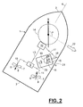
- Fig. 2 is very similar to fig. 1 , except for the orientation of the remote control unit 15 now being altered so that the unit 15 is no longer aligned with the main axis 4 of the boat 1.
- the viewing direction 20 of the helmsman is in the same general direction as the remote control unit 15 is pointing at.
- the helmsman again simply moves the joystick 16 in the desired direction of travel 21 and the boat 1 will travel in the same actual direction of travel 22 as in the previous example of fig. 1 , i.e. coinciding with the desired direction of travel 21.
- the helmsman is no longer forced to mentally recalculate the correct movement of the joystick relative to the orientation of the remote control unit, as is the case with conventional remote control systems. Instead, the boat 1 will simply steer in the direction in which the joystick is pointing - regardless of the orientation of the remote control unit 15 relative to the main axis 4 of the boat 1. This substantially facilitates the maneuvering of the boat.
- a docking situation is shown, in which the helmsman is standing ashore on a dock or jetty 23 with the remote control unit 15, whilst maneuvering the boat 1 towards him and alongside the jetty 23. Again, the helmsman simply points the joystick in the desired direction of travel 21, resulting in the boat 1 moving in an identical actual direction of travel 22 towards the jetty 23. In this way, the helmsman is able to gently pilot the boat 1 alongside the jetty 23 by intuitively performing highly precise maneuvers.
- the boat 1 is further provided with a bow thruster assembly 28, a starboard rudder 32 and a port rudder 34.
- the bow thruster assembly 28 is oriented substantially transversally to the main axis 4 and is directly linked to the steering computer 12 via a communication link 31.
- the bow thruster assembly 28 may be indirectly linked to the steering computer 12 via - for example - the steering mechanism 9.
- the starboard rudder 32 and the port rudder 34 are directly linked to the steering computer 12 via communication links 33 and 35 respectively.
- the rudders 32 and 34 may be indirectly linked to the steering computer 12 via - for example - the steering mechanism 9.
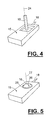
- Fig. 4 shows a simplified perspective image of a remote control unit 15 having a steering input manipulator 16 in the form of a joystick.
- the steering input data includes a desired relative thrust value defined by the degree of inclination from a vertical reference position of the joystick 16. Said vertical reference position is indicated in the figure by the vertical centerline with reference numeral 24.
- Fig. 5 finally shows a simplified perspective image of a remote control unit 15 having a steering input manipulator 16 in the form of a spherical so called tracking-ball.
- the tracking ball 16 is rotatably suspended in an opening 25 in said remote control unit 15.
- the steering input data includes an angle ⁇ (not shown in the figure, but defined in analogy with the previously described angle ⁇ ) between the reference heading and the direction of rotation the tracking-ball 16.
- the direction of rotation is indicated by the dash-dotted line 26 in fig. 5 .
- the steering input data further includes a desired relative thrust value defined by the degree of rotation from a central reference position of the tracking-ball 16. In fig. 5 , said central reference position is indicated by the vertical centerline 27.
- the secondary heading sensor 19 in the remote control unit 15 is suitably a so called flux gate compass.
- a general description of such a compass design is given below, without direct reference to any of the drawing figures:
- a flux gate compass is a device in which the balance of currents in coil windings is affected by the Earth's magnetic field.
- the flux gate compass has two small coils wound on ferrite cores at right-angles to each other. Both are energized in phase at a low frequency usually between 400-1000 Hz.
- the Earth's magnetic field produces a small phase-shift which depends on the angle of the field relative to the coil. If the field is directly aligned with one coil and therefore directly across the other coil, the coil it is aligned with experiences maximum phase-shift and the other none at all.
- a small electronic circuit detects the difference and indicates it digitally.
- a flux gate compass is relatively inexpensive, generally very accurate and does not suffer from the problems a mechanical magnetic compass has with vibration and rapid turns.
- the primary heading sensor 14 may - as mentioned initially - include a gyroscopic compass.
- a gyroscopic compass the axis of a spinning mass tends to remain pointed in a constant direction. This direction does not necessarily have to be north/south related, since a gyroscopic compass is not north seeking on its own, it has to be calibrated with a conventional or flux gate compass.
- both the primary and the secondary heading sensors 14, 19 may include gyroscopic compasses. In such an embodiment, it is possible to use a predetermined reference heading which is not related to the magnetic north.
- a gyroscopic compass comprises a motor and a heavy disk mounted in a set of gimbals (not shown). Sensors on pivots of the gimbals - or otherwise mounted in the housing of the gyro detect the relative movement between the axis of the gyro and the housing of the gyro.
- the remote control system will function regardless of the local deviation from true north, since both heading sensors 14, 19 are synchronized with each other with respect to any set reference heading N.
- the remote control unit 15 may alternatively be communicating with the steering computer 12 via a cable (not shown).
- the boat 1 may be equipped with more than two propulsion drives 5, 6.
- the principle of the invention is also applicable to a boat with a single propulsion drive (not shown).
- the remote control system in its broadest sense is applicable to any type of vehicle operating on land, at sea or in the air.
Landscapes
- Engineering & Computer Science (AREA)
- Physics & Mathematics (AREA)
- Automation & Control Theory (AREA)
- Remote Sensing (AREA)
- Radar, Positioning & Navigation (AREA)
- General Physics & Mathematics (AREA)
- Aviation & Aerospace Engineering (AREA)
- Computing Systems (AREA)
- Mathematical Physics (AREA)
- Theoretical Computer Science (AREA)
- Control Of Position, Course, Altitude, Or Attitude Of Moving Bodies (AREA)
- Toys (AREA)
- Selective Calling Equipment (AREA)
- Lock And Its Accessories (AREA)
Claims (15)
- Système de télécommande pour un véhicule (1) comprenant :- un détecteur de cap primaire (14) fixé de manière permanente au véhicule (1), ledit détecteur de cap primaire (14) étant conçu pour détecter un cap de référence (N) ;- une unité de télécommande (15) comprenant un manipulateur d'entrées de pilotage (16), ladite unité de télécommande (15) pouvant être portée par un utilisateur, l'unité de télécommande (15) étant conçue pour communiquer des données d'entrée de pilotage à- un ordinateur de pilotage (12) programmé pour transformer les données d'entrée de pilotage en commandes de pilotage et pour communiquer les commandes de pilotage à un mécanisme de pilotage (9) du véhicule (1),caractérisé en ce que- ladite unité de télécommande (15) comprend un détecteur de cap secondaire (19) qui est synchronisé avec ledit détecteur de cap primaire (14) par rapport audit cap de référence, et en ce que- lesdites données d'entrée de pilotage comprennent des informations d'une position active dudit manipulateur d'entrées de pilotage (16) par rapport au cap de référence (N), ladite position active du manipulateur d'entrées de pilotage (16) déterminant la direction de déplacement souhaitée du véhicule (1) quelle que soit l'orientation de l'unité de télécommande (15) par rapport à l'axe principal (4) du véhicule (1).
- Système de télécommande selon la revendication 1, caractérisé en ce que lesdits détecteurs de cap primaire et secondaire (14, 19) comprennent chacun une boussole, et en ce que ledit cap de référence (N) correspond au pôle nord magnétique, ou est sinon associé à celui-ci.
- Système de télécommande selon la revendication 2, caractérisé en ce que le détecteur de cap secondaire (19) comprend une boussole d'induction.
- Système de télécommande selon l'une quelconque des revendications précédentes, caractérisé en ce que le manipulateur d'entrées de pilotage (16) comprend un levier de commande.
- Système de télécommande selon la revendication 4, caractérisé en ce que les données d'entrée de pilotage comprennent un angle projeté (α) entre le cap de référence (N) et la direction d'inclinaison du levier de commande (16).
- Système de télécommande selon la revendication 5, caractérisé en ce que les données d'entrée de pilotage comprennent une valeur de poussée relative souhaitée définie par le degré d'inclinaison à partir d'une position de référence verticale (24) du levier de commande (16).
- Système de télécommande selon l'une quelconque des revendications précédentes, caractérisé en ce que le détecteur de cap secondaire (19) est synchronisé de manière continue avec le détecteur de cap primaire (14).
- Système de télécommande selon l'une quelconque des revendications précédentes, caractérisé en ce que ladite unité de télécommande (15) est conçue pour une communication sans fil avec l'ordinateur de pilotage (12).
- Système de télécommande selon l'une quelconque des revendications précédentes, caractérisé en ce que ledit manipulateur d'entrées de pilotage (16) comprend une boule de commande essentiellement sphérique.
- Système de télécommande selon la revendication 9, caractérisé en ce que lesdites données d'entrée de pilotage comprennent un angle (β) entre le cap de référence (N) et la direction de rotation (26) de la boule de commande (16).
- Système de télécommande selon la revendication 10, caractérisé en ce que les données d'entrée de pilotage comprennent en outre une valeur de poussée relative souhaitée définie par le degré de rotation à partir d'une position de référence centrale (27) de la balle de commande (16).
- Navire se déplaçant sur l'eau comprenant de multiples entraînements de propulsion orientables (5, 6), caractérisé en ce qu'il est muni d'un système de télécommande selon l'une quelconque des revendications précédentes.
- Navire se déplaçant sur l'eau selon la revendication 12, caractérisé en ce que les commandes de pilotage provenant de l'ordinateur de pilotage (12) comprennent des valeurs de poussée et d'angle de pilotage calculées individuellement pour chaque entraînement de propulsion (5, 6), nécessaires pour déplacer le navire (1) dans la direction de déplacement souhaitée (21) telle qu'indiquée par le manipulateur d'entrées de pilotage (16).
- Navire se déplaçant sur l'eau selon la revendication 12 ou 13, caractérisé en ce que le navire se déplaçant sur l'eau (1) comprend en outre un ensemble propulseur d'étrave (28) orienté essentiellement transversalement à l'axe principal (4), ledit ensemble propulseur d'étrave (28) étant relié directement ou indirectement à l'ordinateur de pilotage (12).
- Navire se déplaçant sur l'eau selon la revendication 12, 13 ou 14, caractérisé en ce que le navire se déplaçant sur l'eau (1) comprend en outre un ou plusieurs gouvernails (32, 34), lesdits gouvernails (32, 34) étant reliés directement ou indirectement à l'ordinateur de pilotage (12).
Applications Claiming Priority (3)
| Application Number | Priority Date | Filing Date | Title |
|---|---|---|---|
| SE0103812 | 2001-11-16 | ||
| SE0103812A SE521051C2 (sv) | 2001-11-16 | 2001-11-16 | Fjärrmanövreringssystem för ett fordon. |
| PCT/SE2002/002042 WO2003042036A1 (fr) | 2001-11-16 | 2002-11-08 | Systeme de telecommande pour vehicule |
Publications (2)
| Publication Number | Publication Date |
|---|---|
| EP1448436A1 EP1448436A1 (fr) | 2004-08-25 |
| EP1448436B1 true EP1448436B1 (fr) | 2010-04-14 |
Family
ID=20286000
Family Applications (1)
| Application Number | Title | Priority Date | Filing Date |
|---|---|---|---|
| EP02791121A Expired - Lifetime EP1448436B1 (fr) | 2001-11-16 | 2002-11-08 | Systeme de telecommande pour vehicule |
Country Status (6)
| Country | Link |
|---|---|
| US (1) | US7127333B2 (fr) |
| EP (1) | EP1448436B1 (fr) |
| AT (1) | ATE464227T1 (fr) |
| DE (1) | DE60236013D1 (fr) |
| SE (1) | SE521051C2 (fr) |
| WO (1) | WO2003042036A1 (fr) |
Cited By (1)
| Publication number | Priority date | Publication date | Assignee | Title |
|---|---|---|---|---|
| US12459618B2 (en) | 2021-12-22 | 2025-11-04 | Navico, Inc. | Device for steering a trolling motor and method of the same |
Families Citing this family (53)
| Publication number | Priority date | Publication date | Assignee | Title |
|---|---|---|---|---|
| US7952570B2 (en) | 2002-06-08 | 2011-05-31 | Power2B, Inc. | Computer navigation |
| DE10346888A1 (de) * | 2003-10-09 | 2005-05-04 | Daimler Chrysler Ag | Fernsteuereinheit zum Rangieren eines Fahrzeugs |
| US8610675B2 (en) | 2007-03-14 | 2013-12-17 | Power2B, Inc. | Interactive devices |
| US10452207B2 (en) | 2005-05-18 | 2019-10-22 | Power2B, Inc. | Displays and information input devices |
| WO2007030040A1 (fr) * | 2005-09-06 | 2007-03-15 | Cpac Systems Ab | Procede et dispositif destines a etalonner un systeme de commande de poussee et de direction dans un navire |
| US7731588B2 (en) * | 2005-09-28 | 2010-06-08 | The United States Of America As Represented By The Secretary Of The Navy | Remote vehicle control system |
| US7267068B2 (en) | 2005-10-12 | 2007-09-11 | Brunswick Corporation | Method for maneuvering a marine vessel in response to a manually operable control device |
| US7305928B2 (en) | 2005-10-12 | 2007-12-11 | Brunswick Corporation | Method for positioning a marine vessel |
| US7131385B1 (en) | 2005-10-14 | 2006-11-07 | Brunswick Corporation | Method for braking a vessel with two marine propulsion devices |
| US7234983B2 (en) | 2005-10-21 | 2007-06-26 | Brunswick Corporation | Protective marine vessel and drive |
| US7294031B1 (en) | 2005-10-21 | 2007-11-13 | Brunswick Corporation | Marine drive grommet seal |
| US7188581B1 (en) | 2005-10-21 | 2007-03-13 | Brunswick Corporation | Marine drive with integrated trim tab |
| US7267588B1 (en) | 2006-03-01 | 2007-09-11 | Brunswick Corporation | Selectively lockable marine propulsion devices |
| US20090068925A1 (en) * | 2007-09-11 | 2009-03-12 | Southern Taiwan University | Smart remote control system |
| JP5133637B2 (ja) * | 2007-09-14 | 2013-01-30 | ヤマハ発動機株式会社 | 船舶 |
| US8011983B1 (en) | 2008-01-07 | 2011-09-06 | Brunswick Corporation | Marine drive with break-away mount |
| US7867046B1 (en) | 2008-01-07 | 2011-01-11 | Brunswick Corporation | Torsion-bearing break-away mount for a marine drive |
| SI22884A (sl) * | 2008-10-08 | 2010-04-30 | Boris Sobožśan | Naprava za brezĺ˝ižśno daljinsko upravljanje igražś |
| US8089225B2 (en) | 2008-10-29 | 2012-01-03 | Honeywell International Inc. | Systems and methods for inertially controlling a hovering unmanned aerial vehicles |
| ITMI20100142A1 (it) * | 2010-02-02 | 2011-08-03 | Riso Marco De | Sistema automatico di manovra per natanti imbarcazioni e navi a motore con sistema di trasmissione e propulsione in linea d'asse di superficie e fuoribordo |
| DE202010000176U1 (de) * | 2010-02-12 | 2011-06-30 | AL-KO Kober AG, 89359 | Fernbedienung |
| US8866597B2 (en) * | 2010-08-31 | 2014-10-21 | Wolfgang Brendel | Radio remote control with position sensor system |
| US20120115394A1 (en) * | 2010-11-05 | 2012-05-10 | Michael Sivan | Closed-Loop Adaptive Two-Way Remote Controller |
| TW201235263A (en) * | 2011-02-24 | 2012-09-01 | Hon Hai Prec Ind Co Ltd | Control device and method for adjusting control command using the control device |
| TW201235264A (en) * | 2011-02-24 | 2012-09-01 | Hon Hai Prec Ind Co Ltd | Unmanned aerial vehicle and method for controlling the unmanned aerial vehicle |
| TW201235949A (en) * | 2011-02-24 | 2012-09-01 | Hon Hai Prec Ind Co Ltd | Unmanned aerial vehicle and method for adjusting control command of the unmanned aerial vehicle |
| US8676406B2 (en) | 2011-05-03 | 2014-03-18 | Raytheon Company | Unmanned aerial vehicle control using a gamepad |
| US8888544B1 (en) | 2011-12-01 | 2014-11-18 | Enovation Controls, Llc | Versatile control handle for watercraft docking system |
| US9245428B2 (en) | 2012-08-02 | 2016-01-26 | Immersion Corporation | Systems and methods for haptic remote control gaming |
| US9004973B2 (en) | 2012-10-05 | 2015-04-14 | Qfo Labs, Inc. | Remote-control flying copter and method |
| PT106723A (pt) | 2013-01-09 | 2014-07-09 | Far Away Sensing | Sistema e processo de comando remoto de veículos por cópia de orientação espacial compreendendo um subsistema avisador de ordens não executáveis |
| US9213333B2 (en) * | 2013-06-06 | 2015-12-15 | Caterpillar Inc. | Remote operator station |
| CN105518487B (zh) * | 2014-10-27 | 2017-09-12 | 深圳市大疆创新科技有限公司 | 飞行器的位置提示方法及装置 |
| JP2016090348A (ja) * | 2014-10-31 | 2016-05-23 | 古野電気株式会社 | センサ遠隔制御システム、遠隔操作装置、センサ装置、及びセンサ遠隔制御方法 |
| JP6479418B2 (ja) | 2014-10-31 | 2019-03-06 | 古野電気株式会社 | 遠隔操舵システム、遠隔操作装置、及び遠隔操舵方法 |
| US10025312B2 (en) | 2015-02-20 | 2018-07-17 | Navico Holding As | Multiple autopilot interface |
| US9594374B2 (en) | 2015-02-26 | 2017-03-14 | Navico Holding As | Operating multiple autopilots |
| US9441724B1 (en) | 2015-04-06 | 2016-09-13 | Brunswick Corporation | Method and system for monitoring and controlling a transmission |
| US9594375B2 (en) * | 2015-05-14 | 2017-03-14 | Navico Holding As | Heading control using multiple autopilots |
| EP3299920B1 (fr) * | 2015-05-18 | 2021-06-23 | SZ DJI Technology Co., Ltd. | Procédé de commande de véhicule aérien sans pilote et dispositif basé sur un mode sans tête |
| JP6523568B2 (ja) | 2015-08-03 | 2019-06-05 | アピアム インコーポレイティド | 水中ドローン |
| US9969478B2 (en) * | 2015-08-10 | 2018-05-15 | Ben Mazin | Remote controlled boat system |
| US10258888B2 (en) | 2015-11-23 | 2019-04-16 | Qfo Labs, Inc. | Method and system for integrated real and virtual game play for multiple remotely-controlled aircraft |
| CN105700436B (zh) * | 2016-03-09 | 2018-07-31 | 中国人民解放军63686部队 | 一种标校远程监控系统的实现方法 |
| US10082788B1 (en) | 2017-04-20 | 2018-09-25 | Brunswick Corporation | Joystick assembly and system for controlling steering and thrust of a marine propulsion device |
| US10214933B2 (en) | 2017-05-11 | 2019-02-26 | Hayward Industries, Inc. | Pool cleaner power supply |
| US12097843B2 (en) * | 2021-11-24 | 2024-09-24 | Ford Global Technologies, Llc | Remote park assist augmented reality user engagement with cameraless detection |
| US12065230B1 (en) | 2022-02-15 | 2024-08-20 | Brunswick Corporation | Marine propulsion control system and method with rear and lateral marine drives |
| JP2023128321A (ja) * | 2022-03-03 | 2023-09-14 | ヤマハ発動機株式会社 | 操船装置および情報処理システム |
| JP2023138158A (ja) * | 2022-03-18 | 2023-09-29 | 三菱重工業株式会社 | 操船システム |
| US12134454B1 (en) | 2022-07-20 | 2024-11-05 | Brunswick Corporation | Marine propulsion system and method with single rear drive and lateral marine drive |
| US12258115B2 (en) | 2022-07-20 | 2025-03-25 | Brunswick Corporation | Marine propulsion system and joystick control method |
| US12110088B1 (en) | 2022-07-20 | 2024-10-08 | Brunswick Corporation | Marine propulsion system and method with rear and lateral marine drives |
Family Cites Families (8)
| Publication number | Priority date | Publication date | Assignee | Title |
|---|---|---|---|---|
| US3935645A (en) * | 1970-08-13 | 1976-02-03 | Kabushiki Kaisha Komatsu Seisakusho | Apparatus for indicating relative azimuth |
| JPS5917758Y2 (ja) * | 1977-04-20 | 1984-05-23 | ヤマハ発動機株式会社 | 遠融操舵装置 |
| DE3222054A1 (de) * | 1982-06-11 | 1983-12-15 | Schottel-Werft Josef Becker Gmbh & Co Kg, 5401 Spay | Vorrichtung zum vorgeben der bewegungsrichtung und kraft eines wasserfahrzeugs |
| JPS628898A (ja) * | 1985-07-06 | 1987-01-16 | Tokyo Keiki Co Ltd | ジヨイステツク操船装置 |
| US4818990A (en) * | 1987-09-11 | 1989-04-04 | Fernandes Roosevelt A | Monitoring system for power lines and right-of-way using remotely piloted drone |
| WO1994023357A1 (fr) * | 1993-04-02 | 1994-10-13 | Vir Systems Pty. Limited | Ensemble detecteur d'attitude |
| US6694228B2 (en) * | 2002-05-09 | 2004-02-17 | Sikorsky Aircraft Corporation | Control system for remotely operated vehicles for operational payload employment |
| US6697715B1 (en) * | 2002-06-19 | 2004-02-24 | The United States Of America As Represented By The Secretary Of The Navy | Instinctive steering system and method for reducing operator error in controlling a vehicle remotely |
-
2001
- 2001-11-16 SE SE0103812A patent/SE521051C2/sv unknown
-
2002
- 2002-11-08 WO PCT/SE2002/002042 patent/WO2003042036A1/fr not_active Ceased
- 2002-11-08 AT AT02791121T patent/ATE464227T1/de not_active IP Right Cessation
- 2002-11-08 EP EP02791121A patent/EP1448436B1/fr not_active Expired - Lifetime
- 2002-11-08 DE DE60236013T patent/DE60236013D1/de not_active Expired - Lifetime
-
2004
- 2004-05-15 US US10/709,587 patent/US7127333B2/en not_active Expired - Lifetime
Cited By (1)
| Publication number | Priority date | Publication date | Assignee | Title |
|---|---|---|---|---|
| US12459618B2 (en) | 2021-12-22 | 2025-11-04 | Navico, Inc. | Device for steering a trolling motor and method of the same |
Also Published As
| Publication number | Publication date |
|---|---|
| SE521051C2 (sv) | 2003-09-23 |
| SE0103812L (sv) | 2003-05-17 |
| SE0103812D0 (sv) | 2001-11-16 |
| ATE464227T1 (de) | 2010-04-15 |
| DE60236013D1 (de) | 2010-05-27 |
| US7127333B2 (en) | 2006-10-24 |
| WO2003042036A1 (fr) | 2003-05-22 |
| US20060206244A1 (en) | 2006-09-14 |
| EP1448436A1 (fr) | 2004-08-25 |
Similar Documents
| Publication | Publication Date | Title |
|---|---|---|
| EP1448436B1 (fr) | Systeme de telecommande pour vehicule | |
| EP2328801B1 (fr) | Syteme de manoeuvre d'un bateau par joystick | |
| EP3170735B1 (fr) | Procédé de commande de manoeuvre de bateau pour bateau et bateau équipé d'un système de commande de manoeuvre pour bateau | |
| JP6466600B1 (ja) | 推進器の制御装置 | |
| EP1775211A2 (fr) | Embarcation et méthode pour le positionnement | |
| JP7240739B2 (ja) | 自動航行一軸二舵船 | |
| US20080269968A1 (en) | Watercraft position management system & method | |
| US20250153838A1 (en) | Uniaxial twin-rudder ship having automatic docking function | |
| JP6532507B2 (ja) | 一軸二舵船の操舵制御装置 | |
| JP5972201B2 (ja) | 操船システム | |
| JP2025101123A (ja) | 船舶用航海監視ロボットおよび自動航行一軸二舵船の避航操船システム | |
| JP2000344193A (ja) | 自動復帰航行装置 | |
| JP7328692B2 (ja) | 緊急制御機能を備えた自動航行一軸二舵船 | |
| AU2021107112A4 (en) | Automated steering system and method for a marine vessel | |
| US20240149999A1 (en) | Watercraft propulsion system, and watercraft including the watercraft propulsion system | |
| JP2003202922A (ja) | 無線操縦システム、及び無線操縦方法 | |
| JP2014184846A (ja) | 操船システム及びそれを備える船舶 | |
| WO2014148168A1 (fr) | Système de manœuvre de bateau, et bateau équipé de celui-ci | |
| EP4215436B1 (fr) | Dispositif de joystick pour véhicule | |
| EP4632521B1 (fr) | Commande de pilotage automatique d'un navire | |
| JP7634290B2 (ja) | 自動航行一軸二舵船の避航操船システム | |
| JP7690043B2 (ja) | 船舶操縦システム | |
| JP7668453B2 (ja) | 船舶、船舶制御装置、船舶制御方法およびプログラム | |
| US20240400184A1 (en) | Method for Controlling an Unmanned Surface Vessel | |
| US20250382045A1 (en) | Joystick systems and methods for marine propulsion systems |
Legal Events
| Date | Code | Title | Description |
|---|---|---|---|
| PUAI | Public reference made under article 153(3) epc to a published international application that has entered the european phase |
Free format text: ORIGINAL CODE: 0009012 |
|
| 17P | Request for examination filed |
Effective date: 20040616 |
|
| AK | Designated contracting states |
Kind code of ref document: A1 Designated state(s): AT BE BG CH CY CZ DE DK EE ES FI FR GB GR IE IT LI LU MC NL PT SE SK TR |
|
| AX | Request for extension of the european patent |
Extension state: AL LT LV MK RO SI |
|
| 17Q | First examination report despatched |
Effective date: 20061027 |
|
| GRAP | Despatch of communication of intention to grant a patent |
Free format text: ORIGINAL CODE: EPIDOSNIGR1 |
|
| GRAS | Grant fee paid |
Free format text: ORIGINAL CODE: EPIDOSNIGR3 |
|
| GRAA | (expected) grant |
Free format text: ORIGINAL CODE: 0009210 |
|
| AK | Designated contracting states |
Kind code of ref document: B1 Designated state(s): AT BE BG CH CY CZ DE DK EE ES FI FR GB GR IE IT LI LU MC NL PT SE SK TR |
|
| REG | Reference to a national code |
Ref country code: GB Ref legal event code: FG4D |
|
| REG | Reference to a national code |
Ref country code: CH Ref legal event code: EP |
|
| REG | Reference to a national code |
Ref country code: IE Ref legal event code: FG4D |
|
| REF | Corresponds to: |
Ref document number: 60236013 Country of ref document: DE Date of ref document: 20100527 Kind code of ref document: P |
|
| REG | Reference to a national code |
Ref country code: NL Ref legal event code: VDEP Effective date: 20100414 |
|
| PG25 | Lapsed in a contracting state [announced via postgrant information from national office to epo] |
Ref country code: ES Free format text: LAPSE BECAUSE OF FAILURE TO SUBMIT A TRANSLATION OF THE DESCRIPTION OR TO PAY THE FEE WITHIN THE PRESCRIBED TIME-LIMIT Effective date: 20100725 Ref country code: NL Free format text: LAPSE BECAUSE OF FAILURE TO SUBMIT A TRANSLATION OF THE DESCRIPTION OR TO PAY THE FEE WITHIN THE PRESCRIBED TIME-LIMIT Effective date: 20100414 Ref country code: SE Free format text: LAPSE BECAUSE OF FAILURE TO SUBMIT A TRANSLATION OF THE DESCRIPTION OR TO PAY THE FEE WITHIN THE PRESCRIBED TIME-LIMIT Effective date: 20100414 |
|
| PG25 | Lapsed in a contracting state [announced via postgrant information from national office to epo] |
Ref country code: FI Free format text: LAPSE BECAUSE OF FAILURE TO SUBMIT A TRANSLATION OF THE DESCRIPTION OR TO PAY THE FEE WITHIN THE PRESCRIBED TIME-LIMIT Effective date: 20100414 Ref country code: AT Free format text: LAPSE BECAUSE OF FAILURE TO SUBMIT A TRANSLATION OF THE DESCRIPTION OR TO PAY THE FEE WITHIN THE PRESCRIBED TIME-LIMIT Effective date: 20100414 |
|
| PG25 | Lapsed in a contracting state [announced via postgrant information from national office to epo] |
Ref country code: GR Free format text: LAPSE BECAUSE OF FAILURE TO SUBMIT A TRANSLATION OF THE DESCRIPTION OR TO PAY THE FEE WITHIN THE PRESCRIBED TIME-LIMIT Effective date: 20100715 Ref country code: CY Free format text: LAPSE BECAUSE OF FAILURE TO SUBMIT A TRANSLATION OF THE DESCRIPTION OR TO PAY THE FEE WITHIN THE PRESCRIBED TIME-LIMIT Effective date: 20100414 |
|
| PG25 | Lapsed in a contracting state [announced via postgrant information from national office to epo] |
Ref country code: PT Free format text: LAPSE BECAUSE OF FAILURE TO SUBMIT A TRANSLATION OF THE DESCRIPTION OR TO PAY THE FEE WITHIN THE PRESCRIBED TIME-LIMIT Effective date: 20100816 Ref country code: DK Free format text: LAPSE BECAUSE OF FAILURE TO SUBMIT A TRANSLATION OF THE DESCRIPTION OR TO PAY THE FEE WITHIN THE PRESCRIBED TIME-LIMIT Effective date: 20100414 Ref country code: EE Free format text: LAPSE BECAUSE OF FAILURE TO SUBMIT A TRANSLATION OF THE DESCRIPTION OR TO PAY THE FEE WITHIN THE PRESCRIBED TIME-LIMIT Effective date: 20100414 |
|
| PLBE | No opposition filed within time limit |
Free format text: ORIGINAL CODE: 0009261 |
|
| STAA | Information on the status of an ep patent application or granted ep patent |
Free format text: STATUS: NO OPPOSITION FILED WITHIN TIME LIMIT |
|
| PG25 | Lapsed in a contracting state [announced via postgrant information from national office to epo] |
Ref country code: SK Free format text: LAPSE BECAUSE OF FAILURE TO SUBMIT A TRANSLATION OF THE DESCRIPTION OR TO PAY THE FEE WITHIN THE PRESCRIBED TIME-LIMIT Effective date: 20100414 Ref country code: BE Free format text: LAPSE BECAUSE OF FAILURE TO SUBMIT A TRANSLATION OF THE DESCRIPTION OR TO PAY THE FEE WITHIN THE PRESCRIBED TIME-LIMIT Effective date: 20100414 Ref country code: CZ Free format text: LAPSE BECAUSE OF FAILURE TO SUBMIT A TRANSLATION OF THE DESCRIPTION OR TO PAY THE FEE WITHIN THE PRESCRIBED TIME-LIMIT Effective date: 20100414 |
|
| 26N | No opposition filed |
Effective date: 20110117 |
|
| PG25 | Lapsed in a contracting state [announced via postgrant information from national office to epo] |
Ref country code: IT Free format text: LAPSE BECAUSE OF FAILURE TO SUBMIT A TRANSLATION OF THE DESCRIPTION OR TO PAY THE FEE WITHIN THE PRESCRIBED TIME-LIMIT Effective date: 20100414 |
|
| PG25 | Lapsed in a contracting state [announced via postgrant information from national office to epo] |
Ref country code: MC Free format text: LAPSE BECAUSE OF NON-PAYMENT OF DUE FEES Effective date: 20101130 |
|
| REG | Reference to a national code |
Ref country code: CH Ref legal event code: PL |
|
| PG25 | Lapsed in a contracting state [announced via postgrant information from national office to epo] |
Ref country code: LI Free format text: LAPSE BECAUSE OF NON-PAYMENT OF DUE FEES Effective date: 20101130 Ref country code: CH Free format text: LAPSE BECAUSE OF NON-PAYMENT OF DUE FEES Effective date: 20101130 |
|
| PG25 | Lapsed in a contracting state [announced via postgrant information from national office to epo] |
Ref country code: IE Free format text: LAPSE BECAUSE OF NON-PAYMENT OF DUE FEES Effective date: 20101108 |
|
| PG25 | Lapsed in a contracting state [announced via postgrant information from national office to epo] |
Ref country code: BG Free format text: LAPSE BECAUSE OF FAILURE TO SUBMIT A TRANSLATION OF THE DESCRIPTION OR TO PAY THE FEE WITHIN THE PRESCRIBED TIME-LIMIT Effective date: 20100414 Ref country code: LU Free format text: LAPSE BECAUSE OF NON-PAYMENT OF DUE FEES Effective date: 20101108 |
|
| PG25 | Lapsed in a contracting state [announced via postgrant information from national office to epo] |
Ref country code: TR Free format text: LAPSE BECAUSE OF FAILURE TO SUBMIT A TRANSLATION OF THE DESCRIPTION OR TO PAY THE FEE WITHIN THE PRESCRIBED TIME-LIMIT Effective date: 20100414 |
|
| PG25 | Lapsed in a contracting state [announced via postgrant information from national office to epo] |
Ref country code: BG Free format text: LAPSE BECAUSE OF FAILURE TO SUBMIT A TRANSLATION OF THE DESCRIPTION OR TO PAY THE FEE WITHIN THE PRESCRIBED TIME-LIMIT Effective date: 20100714 |
|
| REG | Reference to a national code |
Ref country code: FR Ref legal event code: PLFP Year of fee payment: 14 |
|
| REG | Reference to a national code |
Ref country code: FR Ref legal event code: PLFP Year of fee payment: 15 |
|
| REG | Reference to a national code |
Ref country code: FR Ref legal event code: PLFP Year of fee payment: 16 |
|
| PGFP | Annual fee paid to national office [announced via postgrant information from national office to epo] |
Ref country code: DE Payment date: 20191129 Year of fee payment: 18 |
|
| PGFP | Annual fee paid to national office [announced via postgrant information from national office to epo] |
Ref country code: FR Payment date: 20191126 Year of fee payment: 18 |
|
| PGFP | Annual fee paid to national office [announced via postgrant information from national office to epo] |
Ref country code: GB Payment date: 20191128 Year of fee payment: 18 |
|
| REG | Reference to a national code |
Ref country code: DE Ref legal event code: R119 Ref document number: 60236013 Country of ref document: DE |
|
| GBPC | Gb: european patent ceased through non-payment of renewal fee |
Effective date: 20201108 |
|
| PG25 | Lapsed in a contracting state [announced via postgrant information from national office to epo] |
Ref country code: FR Free format text: LAPSE BECAUSE OF NON-PAYMENT OF DUE FEES Effective date: 20201130 |
|
| PG25 | Lapsed in a contracting state [announced via postgrant information from national office to epo] |
Ref country code: GB Free format text: LAPSE BECAUSE OF NON-PAYMENT OF DUE FEES Effective date: 20201108 Ref country code: DE Free format text: LAPSE BECAUSE OF NON-PAYMENT OF DUE FEES Effective date: 20210601 |