EP1450041A1 - Circuit de réfrigérant avec un compresseur à plateau oscillant regle - Google Patents
Circuit de réfrigérant avec un compresseur à plateau oscillant regle Download PDFInfo
- Publication number
- EP1450041A1 EP1450041A1 EP04000690A EP04000690A EP1450041A1 EP 1450041 A1 EP1450041 A1 EP 1450041A1 EP 04000690 A EP04000690 A EP 04000690A EP 04000690 A EP04000690 A EP 04000690A EP 1450041 A1 EP1450041 A1 EP 1450041A1
- Authority
- EP
- European Patent Office
- Prior art keywords
- refrigerant
- swash plate
- pressure
- control valve
- compressor
- Prior art date
- Legal status (The legal status is an assumption and is not a legal conclusion. Google has not performed a legal analysis and makes no representation as to the accuracy of the status listed.)
- Withdrawn
Links
- 239000003507 refrigerant Substances 0.000 title claims abstract description 84
- 230000001105 regulatory effect Effects 0.000 claims abstract description 12
- 239000007788 liquid Substances 0.000 claims description 8
- 238000000034 method Methods 0.000 claims description 8
- 238000004378 air conditioning Methods 0.000 claims description 6
- 238000001816 cooling Methods 0.000 description 11
- 241000270295 Serpentes Species 0.000 description 2
- 230000008859 change Effects 0.000 description 2
- 230000008569 process Effects 0.000 description 2
- 230000001143 conditioned effect Effects 0.000 description 1
- 238000011217 control strategy Methods 0.000 description 1
- 230000007797 corrosion Effects 0.000 description 1
- 238000005260 corrosion Methods 0.000 description 1
- 230000008878 coupling Effects 0.000 description 1
- 238000010168 coupling process Methods 0.000 description 1
- 238000005859 coupling reaction Methods 0.000 description 1
- 125000004122 cyclic group Chemical group 0.000 description 1
- 239000000284 extract Substances 0.000 description 1
- 210000000056 organ Anatomy 0.000 description 1
- 238000013021 overheating Methods 0.000 description 1
- 230000009467 reduction Effects 0.000 description 1
- 230000004044 response Effects 0.000 description 1
- 229920006395 saturated elastomer Polymers 0.000 description 1
Images

Classifications
-
- F—MECHANICAL ENGINEERING; LIGHTING; HEATING; WEAPONS; BLASTING
- F25—REFRIGERATION OR COOLING; COMBINED HEATING AND REFRIGERATION SYSTEMS; HEAT PUMP SYSTEMS; MANUFACTURE OR STORAGE OF ICE; LIQUEFACTION SOLIDIFICATION OF GASES
- F25B—REFRIGERATION MACHINES, PLANTS OR SYSTEMS; COMBINED HEATING AND REFRIGERATION SYSTEMS; HEAT PUMP SYSTEMS
- F25B9/00—Compression machines, plants or systems, in which the refrigerant is air or other gas of low boiling point
- F25B9/002—Compression machines, plants or systems, in which the refrigerant is air or other gas of low boiling point characterised by the refrigerant
- F25B9/008—Compression machines, plants or systems, in which the refrigerant is air or other gas of low boiling point characterised by the refrigerant the refrigerant being carbon dioxide
-
- F—MECHANICAL ENGINEERING; LIGHTING; HEATING; WEAPONS; BLASTING
- F04—POSITIVE - DISPLACEMENT MACHINES FOR LIQUIDS; PUMPS FOR LIQUIDS OR ELASTIC FLUIDS
- F04B—POSITIVE-DISPLACEMENT MACHINES FOR LIQUIDS; PUMPS
- F04B27/00—Multi-cylinder pumps specially adapted for elastic fluids and characterised by number or arrangement of cylinders
- F04B27/08—Multi-cylinder pumps specially adapted for elastic fluids and characterised by number or arrangement of cylinders having cylinders coaxial with, or parallel or inclined to, main shaft axis
- F04B27/14—Control
- F04B27/16—Control of pumps with stationary cylinders
- F04B27/18—Control of pumps with stationary cylinders by varying the relative positions of a swash plate and a cylinder block
- F04B27/1804—Controlled by crankcase pressure
-
- F—MECHANICAL ENGINEERING; LIGHTING; HEATING; WEAPONS; BLASTING
- F25—REFRIGERATION OR COOLING; COMBINED HEATING AND REFRIGERATION SYSTEMS; HEAT PUMP SYSTEMS; MANUFACTURE OR STORAGE OF ICE; LIQUEFACTION SOLIDIFICATION OF GASES
- F25B—REFRIGERATION MACHINES, PLANTS OR SYSTEMS; COMBINED HEATING AND REFRIGERATION SYSTEMS; HEAT PUMP SYSTEMS
- F25B49/00—Arrangement or mounting of control or safety devices
- F25B49/02—Arrangement or mounting of control or safety devices for compression type machines, plants or systems
- F25B49/022—Compressor control arrangements
-
- F—MECHANICAL ENGINEERING; LIGHTING; HEATING; WEAPONS; BLASTING
- F04—POSITIVE - DISPLACEMENT MACHINES FOR LIQUIDS; PUMPS FOR LIQUIDS OR ELASTIC FLUIDS
- F04B—POSITIVE-DISPLACEMENT MACHINES FOR LIQUIDS; PUMPS
- F04B27/00—Multi-cylinder pumps specially adapted for elastic fluids and characterised by number or arrangement of cylinders
- F04B27/08—Multi-cylinder pumps specially adapted for elastic fluids and characterised by number or arrangement of cylinders having cylinders coaxial with, or parallel or inclined to, main shaft axis
- F04B27/14—Control
- F04B27/16—Control of pumps with stationary cylinders
- F04B27/18—Control of pumps with stationary cylinders by varying the relative positions of a swash plate and a cylinder block
- F04B27/1804—Controlled by crankcase pressure
- F04B2027/184—Valve controlling parameter
- F04B2027/1854—External parameters
-
- F—MECHANICAL ENGINEERING; LIGHTING; HEATING; WEAPONS; BLASTING
- F25—REFRIGERATION OR COOLING; COMBINED HEATING AND REFRIGERATION SYSTEMS; HEAT PUMP SYSTEMS; MANUFACTURE OR STORAGE OF ICE; LIQUEFACTION SOLIDIFICATION OF GASES
- F25B—REFRIGERATION MACHINES, PLANTS OR SYSTEMS; COMBINED HEATING AND REFRIGERATION SYSTEMS; HEAT PUMP SYSTEMS
- F25B2309/00—Gas cycle refrigeration machines
- F25B2309/06—Compression machines, plants or systems characterised by the refrigerant being carbon dioxide
- F25B2309/061—Compression machines, plants or systems characterised by the refrigerant being carbon dioxide with cycle highest pressure above the supercritical pressure
-
- F—MECHANICAL ENGINEERING; LIGHTING; HEATING; WEAPONS; BLASTING
- F25—REFRIGERATION OR COOLING; COMBINED HEATING AND REFRIGERATION SYSTEMS; HEAT PUMP SYSTEMS; MANUFACTURE OR STORAGE OF ICE; LIQUEFACTION SOLIDIFICATION OF GASES
- F25B—REFRIGERATION MACHINES, PLANTS OR SYSTEMS; COMBINED HEATING AND REFRIGERATION SYSTEMS; HEAT PUMP SYSTEMS
- F25B2600/00—Control issues
- F25B2600/02—Compressor control
- F25B2600/023—Compressor control controlling swash plate angles
-
- F—MECHANICAL ENGINEERING; LIGHTING; HEATING; WEAPONS; BLASTING
- F25—REFRIGERATION OR COOLING; COMBINED HEATING AND REFRIGERATION SYSTEMS; HEAT PUMP SYSTEMS; MANUFACTURE OR STORAGE OF ICE; LIQUEFACTION SOLIDIFICATION OF GASES
- F25B—REFRIGERATION MACHINES, PLANTS OR SYSTEMS; COMBINED HEATING AND REFRIGERATION SYSTEMS; HEAT PUMP SYSTEMS
- F25B2700/00—Sensing or detecting of parameters; Sensors therefor
- F25B2700/19—Pressures
- F25B2700/193—Pressures of the compressor
- F25B2700/1933—Suction pressures
-
- F—MECHANICAL ENGINEERING; LIGHTING; HEATING; WEAPONS; BLASTING
- F25—REFRIGERATION OR COOLING; COMBINED HEATING AND REFRIGERATION SYSTEMS; HEAT PUMP SYSTEMS; MANUFACTURE OR STORAGE OF ICE; LIQUEFACTION SOLIDIFICATION OF GASES
- F25B—REFRIGERATION MACHINES, PLANTS OR SYSTEMS; COMBINED HEATING AND REFRIGERATION SYSTEMS; HEAT PUMP SYSTEMS
- F25B2700/00—Sensing or detecting of parameters; Sensors therefor
- F25B2700/21—Temperatures
- F25B2700/2117—Temperatures of an evaporator
- F25B2700/21174—Temperatures of an evaporator of the refrigerant at the inlet of the evaporator
-
- F—MECHANICAL ENGINEERING; LIGHTING; HEATING; WEAPONS; BLASTING
- F25—REFRIGERATION OR COOLING; COMBINED HEATING AND REFRIGERATION SYSTEMS; HEAT PUMP SYSTEMS; MANUFACTURE OR STORAGE OF ICE; LIQUEFACTION SOLIDIFICATION OF GASES
- F25B—REFRIGERATION MACHINES, PLANTS OR SYSTEMS; COMBINED HEATING AND REFRIGERATION SYSTEMS; HEAT PUMP SYSTEMS
- F25B40/00—Subcoolers, desuperheaters or superheaters
Definitions
- the invention relates to a refrigerant circuit with a regulated swash plate compressor, in particular for a motor vehicle air conditioning system operated with the refrigerant R744 (CO 2 refrigerant).
- the air that is supplied to the passenger compartment is at one Heat exchanger (evaporator) cooled, the refrigerant conducted in it evaporates and extracts the required amount of heat from the air flowing past.
- the refrigerant is conditioned by changes in state, so that a limited amount of refrigerant is sufficient to cool the air.
- the gas cooler or condenser refrigerant condenser
- the amount of heat supplied to the evaporator by the outside air withdrawn again for which purpose between the refrigerant and the outside air Temperature difference must prevail.
- the gaseous refrigerant is in one Compressor compresses and increases in temperature before it enters the gas cooler is directed and liquefied there. Between the evaporator and the gas cooler is the further arranged an expansion device to the compressed in the compressor and thus refrigerants provided with a higher pressure and a higher temperature to relax again and to regulate the refrigerant flow.
- Compressor and Expansion valves separate the refrigerant circuit into a high pressure and one Low pressure area.
- Swashplate compressors are usually used in motor vehicle air conditioning systems (Compressors) used.
- Compressor is a rotary movement which is arranged in a crankcase Swashplate over connecting elements or coupling links in a back and forth Moving movement implemented by pistons movably arranged in cylinders.
- gaseous refrigerant drawn in from a suction chamber is compressed and discharged through an exhaust chamber.
- the stroke of the pistons changes to Agreement with changes in the swash plate inclination angle.
- This Tilt angle is controlled in a known manner by regulating the pressure in the Crank chamber in which the swash plate is arranged, with reference to the intake pressure set in the cylinder, this pressure by a housed in the cylinder block Control valve is regulated.
- the swash plate inclination changed to the delivery capacity of the compressor to the required cooling capacity adapt.
- this is through a control spring in the direction of reducing its inclination, i.e. in the direction a reduction in the stroke volume, preloaded.
- the proposed refrigerant circuit consists of a swash plate compressor (Compressor), at the outlet of which a high pressure section with a gas cooler or Refrigerant condenser and on its suction side (compressor inlet) Low pressure section are connected to an evaporator, and the High pressure section with adjustable connecting the low pressure section Expansion device, which are connected to each other by a refrigerant line, and a control valve on the suction side of the compressor, through which the refrigerant is sucked back into this, being in front of the inlet of the evaporator Temperature sensor or a pressure sensor in the suction line in front of the compressor is arranged, the control electronics with the actuator of the control valve in There is an operative connection, and that the tilt-adjustable swash plate, the control valve and the respective sensor form a suction pressure control circuit.
- Compressor swash plate compressor
- the control valve is a 3-way valve with a suction pressure, a high pressure and a Crank chamber connection.
- the temperature sensor measures the saturation temperature at Evaporator input from which is stored in a control electronics Vapor pressure curve of the respective refrigerant, the evaporator pressure and thus also the Suction pressure is determined. This eliminates the need for complicated and time-consuming regulation several sensors. Instead of a pressure sensor in the suction line, the Compressor a temperature sensor used in front of the evaporator inlet, because of this is cheaper.
- the control strategy provides that the suction pressure is independent of keep the speed of the compressor constant. This means that the piston stroke at high engine and thus compressor speeds are low and at maximum when idling.
- the refrigerant circuit controlled in this way enables rapid adjustment of the Compressor output for the respective cooling requirement.
- the control valve is preferably a 3-way valve with a pulse width modulation electromagnetic actuator that has a short response time.
- An internal heat exchanger with the suction line of the compressor can be formed in the outlet line of the refrigerant condenser, through which the high-pressure cooled refrigerant is led to the expansion element and the expanded and vaporous refrigerant is led to the compressor, so that the refrigerant to be expanded and evaporated is cooled , with the consequence that the liquid portion of the refrigerant increases after the expansion and thus more liquid refrigerant is available.
- the internal heat exchanger thus increases the cooling capacity and also the efficiency of the cooling circuit.
- An internal heat exchanger is also advantageous because of the rapid change in operating conditions. This version with an internal heat exchanger is particularly suitable for CO 2 refrigerants.
- a thematic expansion valve is advantageously used as the expansion organ used.
- overheating is on Evaporator outlet increased so that the expansion valve opens wide and the Refrigerant mass flow is increased, making the maximum in the shortest possible time Cooling capacity is achieved.
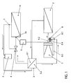
- This refrigerant circuit has a swash plate compressor 1, a gas cooler (refrigerant condenser) 2, an inner heat exchanger 3 with a first refrigerant line coil 3.1, a thermostatic expansion valve 4 of known type with a thermostatic sensor 5, an evaporator 6, at the outlet of which the sensor 5 is arranged, a liquid collector 7 and the heat exchanger 3 with a second refrigerant line coil 3.2 in front of the compressor 1.
- a 3-way control valve 8 is arranged in the valve cover on the suction side of the compressor 1, via which the refrigerant is sucked into the latter.
- This control valve 8 has a connection 8.1 to the suction chamber of the compressor 1, a connection 8.2 to its high pressure chamber, a connection 8.3 to its crank chamber and an electromagnetic actuator 8.4 (not shown further), which is operatively connected to these connections 8.1 to 8.3.
- the actuator 8.4 is connected to control electronics 9, in which the CO 2 vapor pressure curve is stored and which receives as an input variable the saturation temperature of the refrigerant at the inlet of the evaporator 6 from a temperature sensor 10 arranged there.
- the CO 2 refrigerant which has a pressure of approximately 35 to 45 bar and a temperature of approximately 20 ° C. on the suction side of the compressor 1, is compressed in the compressor 1 to a pressure of essentially 110 bar, the temperature of the Refrigerant rises to approx. 100 ° C.
- the gas cooler 2 the refrigerant is cooled to approx. 55 ° to 60 ° C by the outside air flowing past and liquefied in the process.
- the heat extracted from the CO 2 refrigerant is dissipated with the outside air.
- the CO 2 refrigerant flowing through the line coil 3.1 gives heat to the one flowing through the line coil 3.2
- Refrigerant from which is integrated in the suction line of the compressor, wherein it is cooled to a temperature of substantially 25 ° C.
- the liquid CO 2 refrigerant which has a pressure of about 110 bar and a temperature of essentially 25 ° C. on the high pressure side, is converted into the wet vapor state, where it is expanded and released to a pressure of 35 to 45 bar a temperature of 0 ° to 10 ° C is cooled.
- the CO 2 refrigerant enters the evaporator 6, where it evaporates by absorbing heat from the outside or recirculated air to be cooled for the passenger compartment at a constant pressure of 35 to 45 bar, which corresponds to the suction pressure at the compressor 1.
- the expansion valve 4 as an adjustable mass flow valve is set so that the refrigerant mass flow passing through the expansion valve 4 for cooling the air is set so that the refrigerant in the evaporator 6 is converted as completely as possible into the gaseous state and at the evaporator outlet by about 2 ° to 4 ° C is overheated.
- the gaseous refrigerant then flows through the liquid collector 7 in order to retain residues of liquid refrigerant.
- Saturated wet CO 2 is present at the evaporator inlet, the saturation temperature of which depends on the output of the compressor 1. If the compressor 1 generates a high CO 2 mass flow and a greater cooling capacity than the target cooling capacity due to a high speed of the vehicle engine with which it is coupled, the saturation temperature at the evaporator inlet and thus also the saturation pressure drop. In order to reduce the mass flow and thus the cooling capacity of the compressor 1, the piston stroke in this must be reduced. This is done with the help of the central control electronics 9 and the pulse-width-modulated control valve 8, which is coupled to the central control electronics 9, which receives the saturation temperature of the CO refrigerant from the temperature sensor 10.
- the suction pressure in the compressor 1 is kept essentially constant, regardless of the speed of the compressor, via the control valve 8.
- the inclination of the swash plate in this must be reduced. This is done by changing the pressure difference between the pressure in the crank chamber and the pressure in the suction chamber of the compressor 1. Consequently, with the pressure in the suction chamber remaining constant, the pressure in the crank chamber must be increased in order to reduce the inclination of the swash plate and the piston stroke.
- the actuator 8.4 of the control valve 8 is adjusted by the control electronics 9 so that gaseous CO 2 refrigerant is pressed into the crank chamber of the compressor 1 from the high-pressure chamber connection 8.2.
Landscapes
- Engineering & Computer Science (AREA)
- Mechanical Engineering (AREA)
- General Engineering & Computer Science (AREA)
- Physics & Mathematics (AREA)
- Thermal Sciences (AREA)
- Chemical & Material Sciences (AREA)
- Chemical Kinetics & Catalysis (AREA)
- Compressors, Vaccum Pumps And Other Relevant Systems (AREA)
Applications Claiming Priority (2)
| Application Number | Priority Date | Filing Date | Title |
|---|---|---|---|
| DE10306394 | 2003-02-15 | ||
| DE10306394A DE10306394A1 (de) | 2003-02-15 | 2003-02-15 | Kältemittelkreislauf mit einem geregelten Taumelscheibenkompressor |
Publications (1)
| Publication Number | Publication Date |
|---|---|
| EP1450041A1 true EP1450041A1 (fr) | 2004-08-25 |
Family
ID=32731018
Family Applications (1)
| Application Number | Title | Priority Date | Filing Date |
|---|---|---|---|
| EP04000690A Withdrawn EP1450041A1 (fr) | 2003-02-15 | 2004-01-15 | Circuit de réfrigérant avec un compresseur à plateau oscillant regle |
Country Status (2)
| Country | Link |
|---|---|
| EP (1) | EP1450041A1 (fr) |
| DE (1) | DE10306394A1 (fr) |
Cited By (1)
| Publication number | Priority date | Publication date | Assignee | Title |
|---|---|---|---|---|
| CN102261773A (zh) * | 2010-05-24 | 2011-11-30 | 上海日立电器有限公司 | 一种热泵热水器系统 |
Citations (4)
| Publication number | Priority date | Publication date | Assignee | Title |
|---|---|---|---|---|
| US5694784A (en) * | 1995-05-10 | 1997-12-09 | Tes Wankel Technische Forschungs-Und Entwicklungsstelle Lindau Gmbh | Vehicle air conditioning system |
| US5964578A (en) * | 1996-04-01 | 1999-10-12 | Kabushiki Kaisha Toyoda Jidoshokki Seisakusho | Control valve in variable displacement compressor |
| EP0952412A2 (fr) * | 1998-04-16 | 1999-10-27 | Kabushiki Kaisha Toyoda Jidoshokki Seisakusho | Système frigorifique et procédé pour son fonctionnement |
| EP1114932A2 (fr) * | 2000-01-07 | 2001-07-11 | Kabushiki Kaisha Toyoda Jidoshokki Seisakusho | Unité de commande d'un compresseur à capacité variable |
Family Cites Families (6)
| Publication number | Priority date | Publication date | Assignee | Title |
|---|---|---|---|---|
| JPH0717151B2 (ja) * | 1987-07-04 | 1995-03-01 | 株式会社豊田自動織機製作所 | 可変容量コンプレッサの運転制御方法 |
| JPH01175517A (ja) * | 1987-12-28 | 1989-07-12 | Diesel Kiki Co Ltd | 車輌用空気調和装置 |
| NO890076D0 (no) * | 1989-01-09 | 1989-01-09 | Sinvent As | Luftkondisjonering. |
| KR950003458Y1 (ko) * | 1990-11-29 | 1995-05-02 | 가부시끼가이샤 도요다지도쇽끼 세이사꾸쇼 | 요동 사판식 압축기의 피스톤 변위기구 |
| CH690189A5 (de) * | 1995-03-10 | 2000-05-31 | Daimler Benz Ag | Verfahren zur Regelung der Leistung einer Anlage für die Kühlung des Fahrgastraumes eines Kraftfahrzeuges. |
| DE10135727B4 (de) * | 2001-07-21 | 2019-07-04 | Volkswagen Ag | Regelventil gespeist mit Wechselspannung und Taumelscheibenkompressor mit diesem Regelventil |
-
2003
- 2003-02-15 DE DE10306394A patent/DE10306394A1/de not_active Withdrawn
-
2004
- 2004-01-15 EP EP04000690A patent/EP1450041A1/fr not_active Withdrawn
Patent Citations (4)
| Publication number | Priority date | Publication date | Assignee | Title |
|---|---|---|---|---|
| US5694784A (en) * | 1995-05-10 | 1997-12-09 | Tes Wankel Technische Forschungs-Und Entwicklungsstelle Lindau Gmbh | Vehicle air conditioning system |
| US5964578A (en) * | 1996-04-01 | 1999-10-12 | Kabushiki Kaisha Toyoda Jidoshokki Seisakusho | Control valve in variable displacement compressor |
| EP0952412A2 (fr) * | 1998-04-16 | 1999-10-27 | Kabushiki Kaisha Toyoda Jidoshokki Seisakusho | Système frigorifique et procédé pour son fonctionnement |
| EP1114932A2 (fr) * | 2000-01-07 | 2001-07-11 | Kabushiki Kaisha Toyoda Jidoshokki Seisakusho | Unité de commande d'un compresseur à capacité variable |
Cited By (1)
| Publication number | Priority date | Publication date | Assignee | Title |
|---|---|---|---|---|
| CN102261773A (zh) * | 2010-05-24 | 2011-11-30 | 上海日立电器有限公司 | 一种热泵热水器系统 |
Also Published As
| Publication number | Publication date |
|---|---|
| DE10306394A1 (de) | 2004-08-26 |
Similar Documents
| Publication | Publication Date | Title |
|---|---|---|
| DE102005007321B4 (de) | Ejektorpumpenkreis mit mehreren Verdampfapparaten | |
| DE102007007570B4 (de) | Kältemittelströmungsmengen-Steuervorrichtung und Ejektorpumpen-Kühlkreissystem damit | |
| EP0701096B1 (fr) | Procédé de fonctionnement d'une installation productrice de froid pour la climatisation de véhicules et installation productrice de froid pour sa mise en oeuvre | |
| DE10321191B4 (de) | Dampfkompressions-Kühlkreislauf | |
| DE102006035881B4 (de) | Ejektorpumpenkühlkreis | |
| DE102010051471B4 (de) | Fahrzeug mit einer Klimaanlage | |
| DE4003651A1 (de) | Transport-kuehlaggregat mit sekundaerkondensator und maximalarbeitsdruck-expansionsventil | |
| DE102010051976A1 (de) | Klimaanlage für ein Kraftfahrzeug | |
| DE10254016A1 (de) | Vorrichtung zur Kühlung von Ladeluft und Verfahren zum Betreiben einer derartigen Vorrichtung | |
| DE10356447A1 (de) | Kältekreislaufvorrichtung | |
| DE102017118425A1 (de) | Kreislaufsystem für ein Fahrzeug und Verfahren dazu | |
| EP2732139A2 (fr) | Dispositif de récupération de la chaleur résiduelle | |
| EP2928710A1 (fr) | Procédé servant à faire fonctionner un circuit de fluide de refroidissement comme une pompe à chaleur, et circuit de fluide de refroidissement pouvant fonctionner comme une pompe à chaleur | |
| EP1342893A2 (fr) | Dispositif de refroidissement de l'air suralimenté et procédé pour faire fonctionner un tel dispositif | |
| EP2018985B1 (fr) | Climatisation pour véhicule automobile et procédé de contrôle correspondant | |
| DE19831792A1 (de) | Kältekreislaufvorrichtung zur Verwendung in einem Kraftfahrzeug | |
| DE10347748A1 (de) | Mehrfachzonen-Temperatursteuersystem | |
| DE102011110551A1 (de) | Kältemittelkreislaufvorrichtung vom Ejektortyp | |
| EP1462281B1 (fr) | Appareil de climatisation avec plusieurs évaporateurs pour véhicule à moteur | |
| DE102006041612A1 (de) | Kühlkreisvorrichtung | |
| DE102004041251A1 (de) | Kompressor oder Klimaanlage | |
| DE60212502T2 (de) | Kältekreislauf | |
| EP1450041A1 (fr) | Circuit de réfrigérant avec un compresseur à plateau oscillant regle | |
| DE102019119751B3 (de) | Verfahren zum Betreiben eines Kältekreislaufs eines Kraftfahrzeugs und Kältekreislauf | |
| WO2000050826A1 (fr) | Systeme de refroidissement a compression a entrainement electrique d'un vehicule |
Legal Events
| Date | Code | Title | Description |
|---|---|---|---|
| PUAI | Public reference made under article 153(3) epc to a published international application that has entered the european phase |
Free format text: ORIGINAL CODE: 0009012 |
|
| AK | Designated contracting states |
Kind code of ref document: A1 Designated state(s): AT BE BG CH CY CZ DE DK EE ES FI FR GB GR HU IE IT LI LU MC NL PT RO SE SI SK TR |
|
| AX | Request for extension of the european patent |
Extension state: AL LT LV MK |
|
| 17P | Request for examination filed |
Effective date: 20050225 |
|
| AKX | Designation fees paid |
Designated state(s): AT BE BG CH CY CZ DE DK EE ES FI FR GB GR HU IE IT LI LU MC NL PT RO SE SI SK TR |
|
| STAA | Information on the status of an ep patent application or granted ep patent |
Free format text: STATUS: THE APPLICATION IS DEEMED TO BE WITHDRAWN |
|
| 18D | Application deemed to be withdrawn |
Effective date: 20051124 |