EP1450302A1 - Systeme de reproduction des couleurs - Google Patents
Systeme de reproduction des couleurs Download PDFInfo
- Publication number
- EP1450302A1 EP1450302A1 EP02802372A EP02802372A EP1450302A1 EP 1450302 A1 EP1450302 A1 EP 1450302A1 EP 02802372 A EP02802372 A EP 02802372A EP 02802372 A EP02802372 A EP 02802372A EP 1450302 A1 EP1450302 A1 EP 1450302A1
- Authority
- EP
- European Patent Office
- Prior art keywords
- display
- color
- spectrum
- expression
- primary
- Prior art date
- Legal status (The legal status is an assumption and is not a legal conclusion. Google has not performed a legal analysis and makes no representation as to the accuracy of the status listed.)
- Withdrawn
Links
- 238000001228 spectrum Methods 0.000 claims abstract description 61
- 230000006870 function Effects 0.000 claims description 44
- 230000003595 spectral effect Effects 0.000 claims description 27
- 238000006243 chemical reaction Methods 0.000 claims description 21
- 238000004364 calculation method Methods 0.000 abstract description 52
- 238000000034 method Methods 0.000 abstract description 30
- 230000014509 gene expression Effects 0.000 description 98
- 239000003086 colorant Substances 0.000 description 23
- 238000010586 diagram Methods 0.000 description 14
- 230000008569 process Effects 0.000 description 8
- 239000013598 vector Substances 0.000 description 7
- 238000012937 correction Methods 0.000 description 6
- 238000000295 emission spectrum Methods 0.000 description 6
- 239000011159 matrix material Substances 0.000 description 6
- 230000035945 sensitivity Effects 0.000 description 6
- 238000013500 data storage Methods 0.000 description 5
- 230000001419 dependent effect Effects 0.000 description 4
- 238000011160 research Methods 0.000 description 4
- 230000000630 rising effect Effects 0.000 description 4
- 238000005286 illumination Methods 0.000 description 3
- 238000000701 chemical imaging Methods 0.000 description 2
- 230000004456 color vision Effects 0.000 description 2
- 238000002474 experimental method Methods 0.000 description 2
- 238000002360 preparation method Methods 0.000 description 2
- 238000012545 processing Methods 0.000 description 2
- 239000000654 additive Substances 0.000 description 1
- 230000000996 additive effect Effects 0.000 description 1
- 230000008859 change Effects 0.000 description 1
- 230000003247 decreasing effect Effects 0.000 description 1
- 238000011161 development Methods 0.000 description 1
- 239000000203 mixture Substances 0.000 description 1
- 238000012986 modification Methods 0.000 description 1
- 230000004048 modification Effects 0.000 description 1
- 230000003287 optical effect Effects 0.000 description 1
- 230000009467 reduction Effects 0.000 description 1
- 238000012552 review Methods 0.000 description 1
- 238000005070 sampling Methods 0.000 description 1
- 230000007704 transition Effects 0.000 description 1
- 230000017105 transposition Effects 0.000 description 1
- 230000000007 visual effect Effects 0.000 description 1
Images


Classifications
-
- H—ELECTRICITY
- H04—ELECTRIC COMMUNICATION TECHNIQUE
- H04N—PICTORIAL COMMUNICATION, e.g. TELEVISION
- H04N1/00—Scanning, transmission or reproduction of documents or the like, e.g. facsimile transmission; Details thereof
- H04N1/46—Colour picture communication systems
- H04N1/54—Conversion of colour picture signals to a plurality of signals some of which represent particular mixed colours, e.g. for textile printing
-
- H—ELECTRICITY
- H04—ELECTRIC COMMUNICATION TECHNIQUE
- H04N—PICTORIAL COMMUNICATION, e.g. TELEVISION
- H04N1/00—Scanning, transmission or reproduction of documents or the like, e.g. facsimile transmission; Details thereof
- H04N1/46—Colour picture communication systems
- H04N1/465—Conversion of monochrome to colour
-
- H—ELECTRICITY
- H04—ELECTRIC COMMUNICATION TECHNIQUE
- H04N—PICTORIAL COMMUNICATION, e.g. TELEVISION
- H04N1/00—Scanning, transmission or reproduction of documents or the like, e.g. facsimile transmission; Details thereof
- H04N1/46—Colour picture communication systems
- H04N1/56—Processing of colour picture signals
- H04N1/60—Colour correction or control
- H04N1/603—Colour correction or control controlled by characteristics of the picture signal generator or the picture reproducer
- H04N1/6052—Matching two or more picture signal generators or two or more picture reproducers
-
- H—ELECTRICITY
- H04—ELECTRIC COMMUNICATION TECHNIQUE
- H04N—PICTORIAL COMMUNICATION, e.g. TELEVISION
- H04N2209/00—Details of colour television systems
- H04N2209/04—Picture signal generators
- H04N2209/041—Picture signal generators using solid-state devices
- H04N2209/042—Picture signal generators using solid-state devices having a single pick-up sensor
- H04N2209/043—Picture signal generators using solid-state devices having a single pick-up sensor using an alternating colour separation filter, e.g. colour wheel or colour LCD
Definitions
- the present invention relates to a color reproduction system, and more particularly, to a color reproduction system for displaying an image of which spectrum is approximated.
- the color image apparatuses include a camera as an example.
- the camera receives a spectrum of a subject using three sensors having different spectral sensitivities and expresses color information on the basis of output signals of the respective sensors.
- the color image apparatuses include a display such as a CRT display as another example.
- the display shows various colors by additively mixing three different colors of an emission spectrum and expresses color information on the basis of input signals.
- Color models generally used as the device-independent colors include the CIE 1931 color model (XYZ color model) standardized by Commission Internationale de l'Eclairage (CIE) and the CIELAB color model constituting a uniform color space based on the XYZ color model.
- CIE 1931 color model standardized by Commission Internationale de l'Eclairage (CIE)
- CIELAB color model constituting a uniform color space based on the XYZ color model.
- the XYZ color model quantitatively expresses a color using XYZ values obtained by a color matching function derived on the basis of color matching experiments.
- the color matching function is obtained from mean characteristic of data derived from color matching experiment done to many trial subjects.
- the color matching function is given to the characteristics of a virtual observer called the CIE 1931 Standard Colorimetric Observer (hereinbelow, referred to as the standard observer).
- the conventional display systems including the above-mentioned input/output systems with multiband inputs and multiprimary-color display are designed to perform faithful color reproduction in consideration of only the standard observer. According to the conventional systems, therefore, faithful color reproduction is not necessarily performed for a person with visual performance different from that of the standard observer or a color model which is different from that of the standard observer.
- the present invention is made in consideration of the above situation and it is an object of the present invention to provide a color reproduction system capable of performing faithful color reproduction for many observers having variations in color matching functions.
- a color reproduction system including: color conversion means for converting spectral data into display signals; and color image display means for performing display on the basis of the display signals, wherein the color conversion means converts spectral data into display signals such that a display spectrum relating to display by the color image display means is approximated to the spectral data in the gamut of the display spectrum which can be realized by the color image display means.
- the color conversion means performs the approximation under condition that colorimetric values of the spectral data match colorimetric values of the display spectrum and then converts the spectral data into the display signals.
- the colorimetric values are calculated in correspondence with each of arbitrary number of functions.
- the color conversion means approximates the spectral data weighted by a desired function to the display spectrum weighted by the desired function.
- the color conversion means performs the approximation using least-squares approximation between the spectral data and the display spectrum.
- the color conversion means performs the approximation using least-squares approximation whereby a display spectrum based on the display signals lies within the gamut of the color image display means.
- N primary colors N ⁇ 4
- N-3 degree of freedom remains.
- the remaining degree of freedom is used under the constraint conditions that colorimetric values match, and further, spectral approximation is performed, so that fine color reproduction for non-specific observers is realized.
- a spectrum at a certain pixel position in an image of a subject to be reproduced is set to S( ⁇ ).
- a color corresponding to the spectrum S( ⁇ ) is reproduced using an N-primary-color display having N primary colors.
- the N-primary-color display reproduces a color using additive color mixture of the N primary colors.
- T denotes transposition of a matrix or vectors.
- the squared errors E are calculated using the difference, as it is, between the display spectrum S d ( ⁇ ) of the N-primary-color display and the spectrum S( ⁇ ) of the subject image.
- the calculation is not limited to the above case.
- the respective spectra are weighted using an arbitrary function W( ⁇ ) and, after that, the squared error therebetween can be obtained.
- S( ⁇ ) and S d ( ⁇ ) in the expression 8 can be replaced respectively with S'( ⁇ ) and S' d ( ⁇ ) given by the following expression 14. [Expression 14]
- the squared error E is given by a quadratic equation with respect to a.
- the constraint conditions are given by a linear equation with respect to a. In other words, this is a quadratic programming problem in which an objective function is expressed as a quadratic equation and constraint conditions are expressed as a linear equation.
- a solution is obtained without considering a possible range of a display signal value of the primary color i, namely, the condition given by the expression 2.
- the obtained solution lies within the range of the condition given by the expression 2, it is the final solution.
- ⁇ 1 to ⁇ N , ⁇ X , ⁇ Y , and ⁇ Z are obtained.
- ⁇ 1 to ⁇ N , ⁇ X , ⁇ Y , and ⁇ Z are expressed as the following expression 18.
- each of ⁇ 1 to ⁇ N given by the expression 18, satisfies the condition with respect to the dynamic range of the display signal value of the primary color i expressed as the expression 2 is determined. If each ⁇ i satisfies the condition, the obtained ⁇ 1 to ⁇ N represent the optimum solution.
- the reduced gradient method which will be described hereinbelow, is used.
- the reduced gradient method is one of successive approximations.
- a convex function E(a) in which an element a (namely, a ⁇ R N ) of an N-dimensional Euclidean space R N is variable, in order to obtain the minimum value, approximation is made from a certain point a 1 in a gradient downwardly in this order of a 2 , a 3 , ... to be converged to the minimum point a*.
- the reduced gradient method can be applied to the problem of obtaining the minimum value of E(a) expressed as the expression 8 under the limitations of the expressions 2 and 3.
- Transition between points in the reduced gradient method is performed as follows.
- a certain point a 1 in the feasible region is set to a starting point.
- a point aimed at advances from the point a 1 in the direction toward - ⁇ E(a 1 ). This direction is opposite to the direction of the normal line to the level surface of E(a 1 ) passing through the point a 1 . In a manner, the direction indicates the direction of the steepest falling gradient.
- the point advances from a 1 in this direction and then stops at a position where the gradient gradually changes from the falling gradient to a rising gradient or at the end of the boundary of the feasible region.
- the stop position is set to a point a 2 .
- the travelling direction is changed at this point a 2 .
- the travelling direction must be determined such that the angle which the travelling direction forms with - ⁇ E(a 1 ) is 90° or smaller and, when the point aimed at advances in the direction, the point aimed at travels in the feasible region.
- the travelling direction is changed, and the point aimed at successively advances in this order of a 3 , a 4 , ... Even if the travelling direction is changed within an angle of 90° or smaller, so long as there is no more point in the feasible region in the changed travelling direction, the last point is the optimum point.
- N variables include (N - 3) independent variables.
- the remaining three variables are dependent variables.
- a 1 , a 2 , and a 3 are ; set to basic variables and a 4 , a 5 , ..., and a N are set to nonbasic variables.
- Those variables and matrices and the vector b are expressed as the following expression 19.
- M and k are defined as expressed as the following expression 27.
- ⁇ a B / ⁇ a R in the second term on the right side of the expression 28 are calculated as expressed as the following expression 29 using the expressions 26 and 27.
- the reduced gradient method is performed according to the following process.
- one point included in the feasible region namely, a solution which satisfies both of the expression 21 indicating the constraint conditions and the expression 22 indicating the domains of variables is found using any means.
- the means for finding the solution include, for example, means disclosed in "Color Conversion Method for Multiprimary Display Using Matrix Switching", T. Ajito et al., OPTICAL REVIEW, Vol. 8, No. 3, 2001, pp. 191-197 (document 5).
- the obtained solution is set to a expressed as the following expression 31.
- a direction vector in the travelling direction is given by the following expression 32.
- ⁇ a R ( ⁇ 4 , ⁇ 5 ,..., ⁇ N )
- the direction vector ⁇ a R points in the direction which forms an angle of 90° or smaller with respect to the direction opposite to the gradient in a R and in which the point aimed at is not out of the feasible region when the point advances in the direction.
- the direction vector can be set so as to satisfy the following expression 33.
- F is partially differentiated with respect to ⁇ i and, after that, a is substituted for a value.
- the point aimed at is advanced from the present point expressed as the expression 31 to the limit of forward movement in the travelling direction obtained by the above step 2 within the feasible region.
- a point at which the gradient changes from the falling gradient to the rising gradient is found.
- ⁇ 1 , ⁇ 2 , and ⁇ 3 are calculated as expressed as the following expression 35.
- ⁇ 1 represents an upper limit which does not exceed the limit of the feasible region with respect to the independent variables ⁇ 4 to ⁇ N
- ⁇ 2 represents an upper limit which does not exceed the limit of the feasible region with respect to the dependent variables ⁇ 1 to ⁇ 3
- ⁇ 3 represents a value which gives a point at which the gradient changes from the falling gradient to the rising gradient.
- the step 2 or 3 is repeated plural times according to circumstances.
- Figs. 1 to 7 illustrate the embodiment of the present invention.
- Fig. 1 is a diagram showing the schematic structure of a color reproduction system.
- the color reproduction system comprises: a multiband camera 1 for shooting a subject 6 irradiated with a shooting illumination light 5; an image converter 2 for converting a color image supplied from the multiband camera 1 into a color image to be output to a six-primary-color display 3, which will be described later; and the six-primary-color display 3 functioning as color image display means for projecting the color image converted through the image converter 2 on, for example, a screen 4.
- the multiband camera 1 captures multiband image data, for example, 16-band image data of the subject 6 irradiated with the shooting illumination light 5 and then outputs the captured image data to the image converter 2.
- the image converter 2 converts the 16-band image data supplied from the multiband camera 1 into six-primary-color image data to be displayed by the six-primary-color display 3 and then outputs the resultant image data to the six-primary-color display 3. The conversion will be described in detail later.
- the six-primary-color display 3 projects the six-primary-color image data supplied from the image converter 2 onto, for example, the screen 4 to observably display the image.
- Fig. 2 is a diagram showing the structure of the multiband camera 1.
- Incident light from the subject 6 is converged by a lens 1a and only light segments having predetermined wavebands are allowed to pass through interference filters 1c, thus the image is formed on a monochrome CCD 1e.
- the number of interference filters 1c is 16 so as to correspond to 16 bands.
- the 16 interference filters 1c are arranged in a filter turret 1b.
- the filter turret 1b is rotated by a motor 1d, so that the interference filters 1c are sequentially disposed in a light path between the lens la and the monochrome CCD 1e. Synchronously with the positioning of each interference filter 1c in the light path, shooting is performed with the monochrome CCD 1e, thus sequentially capturing subject images of 16 bands constituting a spectral sensitivity and corresponding to the respective interference filters 1c.
- Fig. 3 is a diagram showing an example of the spectral sensitivity of the multiband camera 1 having 16 bands.
- the multiband camera 1 has a spectral sensitivity having 16 peaks generated at substantially regular intervals in wavelengths of 380 to 780 nm.
- Multiband image data comprising 16 bands captured by the multiband camera 1 is output to the image converter 2 and is then processed.
- the 16-band spectral sensitivity can be changed according to the application.
- Fig. 4 is a diagram of an emission spectrum comprising six primary colors of the six-primary-color display 3.
- Six-primary-color emission spectral components p 1 ( ⁇ ), p 2 ( ⁇ ), p 3 ( ⁇ ), p 4 ( ⁇ ), p 5 ( ⁇ ), and p 6 ( ⁇ ) are distributed at substantially regular intervals in the wavelengths of 380 to 780 nm.
- Fig. 5 is a block diagram showing the structure of the image converter 2.
- the image converter 2 comprises a spectrum estimation unit 11, a display color conversion unit 12, and a data storage unit 13.
- the spectrum estimation unit 11 receives multiband image data having 16 bands from the multiband camera 1, calculates a subject spectrum constituting spectral data, and then outputs the data to the display color conversion unit 12 constituting color conversion means.
- spectral reflectance obtained by spectral reflectance calculation means, is multiplied by an illumination spectrum, thus obtaining the subject spectrum.
- the display color conversion unit 12 converts the subject spectrum supplied from the spectrum estimation unit 11 into six-primary-color display signals using color reproduction data of the six-primary-color display 3, the color reproduction data being supplied from the data storage unit 13, and then outputs the signals to the six-primary-color display 3.
- the color reproduction data of the six-primary-color display 3 stored in the data storage unit 13 comprises an emission spectrum of the respective primary colors and tone-scale characteristics.
- the emission spectrum comprises 401 data arranged at intervals of 1 nm in the wavelengths of 380 to 780 nm.
- the tone-scale characteristics are data obtained by applying display brightness, which is normalized such that the maximum value equals to 1, to an input signal value of each primary color for every predetermined sampling tone scale.
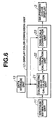
- Fig. 6 is a block diagram showing the structure of the display color conversion unit 12.
- the display color conversion unit 12 comprises a colorimetric-value calculation unit 21, a signal calculation unit 22, and a tone-scale correction unit 23.
- the colorimetric-value calculation unit 21 calculates a spectrum of the six-primary-color display 3 supplied from the data storage unit 13 using the foregoing expression 6 and also calculates colorimetric values of the subject spectrum supplied from the spectrum estimation unit 11 using the foregoing expression 4.
- a color matching function used for calculation of the colorimetric values is selected from among color matching function data, stored in the colorimetric-value calculation unit 21, by the user of the image converter 2.
- the arbitrary number of functions can be used.
- the colorimetric-value calculation unit 21 outputs, to the signal calculation unit 22, the spectrum including the primary colors of the six-primary-color display 3 and the colorimetric values thereof, and the subject spectrum and the colorimetric values thereof.
- the signal calculation unit 22 receives the spectrum including the primary colors of the six-primary-color display 3 and the colorimetric values thereof, and the subject spectrum and the colorimetric values thereof, calculates display signal values of the six-primary-color display 3, and then outputs the values to the tone-scale correction unit 23.
- the signal calculation unit 22 can weight the subject spectrum and the spectrum including the primary colors of the six-primary-color display 3 on the basis of the expression 14.
- the tone-scale correction unit 23 corrects the six-primary-color display signals supplied from the signal calculation unit 22 using the tone-scale characteristics supplied from the data storage unit 13 and then outputs the resultant signals to the six-primary-color display 3.
- Fig. 7 is a block diagram showing the structure of the signal calculation unit 22.
- the signal calculation unit 22 comprises a user setting unit 31, a linear-solution calculation unit 32, and a nonlinear-solution calculation unit 33.
- the user setting unit 31 outputs setting information, indicating whether the linear-solution calculation unit 32 is used, to the linear-solution calculation unit 32 and also generates another setting information, indicating whether the nonlinear-solution calculation unit 33 is used, to the nonlinear-solution calculation unit 33.
- the linear-solution calculation unit 32 calculates six-primary-color display signals for the subject spectrum supplied from the spectrum estimation unit 11 and then outputs the signals together with the subject spectrum to the nonlinear-solution calculation unit 33.
- the linear-solution calculation unit 32 outputs the subject spectrum supplied from the spectrum estimation unit 11 as is to the nonlinear-solution calculation unit 33.
- the nonlinear-solution calculation unit 33 receives the subject spectrum or six-primary-color display signals from the linear-solution calculation unit 32.
- the nonlinear-solution calculation unit 33 calculates six-primary-color display signals to be within the range of 0 to 1 and then outputs the obtained signals to the tone-scale correction unit 23.
- the nonlinear-solution calculation unit 33 When receiving the six-primary-color display signals which are within the range of 0 to 1, the nonlinear-solution calculation unit 33 outputs the received six-primary-color display signals to the tone-scale correction unit 23.
- the nonlinear-solution calculation unit 33 when the user setting unit 31 outputs the setting information indicating that the nonlinear-solution calculation unit 33 is not used, the nonlinear-solution calculation unit 33 outputs the received six-primary-color display signals as they are to the tone-scale correction unit 23. However, when the six-primary-color display signals are not within the range of 0 to 1, the nonlinear-solution calculation unit 33 maps the signal values so as to be within the range of 0 to 1.
- the linear-solution calculation unit 32 calculates display signals on the six-primary-color display 3 using linear quadratic programming. Specifically, the unit 32 utilizes Lagrange's method of undetermined coefficients described in the foregoing principle. In other words, the linear-solution calculation unit 32 calculates display signals ⁇ 1 to ⁇ 6 of the six-primary-color display 3 on the basis of the expression 18 using the primary-color spectrum for the six-primary-color display 3 and the colorimetric values thereof supplied from the colorimetric-value calculation unit 21, the colorimetric values of the subject supplied from the colorimetric-value calculation unit 21, and the subject spectrum supplied from the spectrum estimation unit 11.
- the nonlinear-solution calculation unit 33 calculates display signals of the six-primary-color display 3 using nonlinear quadratic programming. Specifically, the unit 33 utilizes the reduced gradient method described in the foregoing principle. In other words, the nonlinear-solution calculation unit 33 receives the subject spectrum, the colorimetric values thereof, the spectrum of the six-primary-color display 3, and the colorimetric values thereof from the linear-solution calculation unit 32 and performs the processing according to the above-mentioned steps of ⁇ step 1> to ⁇ step 3> to calculate the display signals ⁇ 1 to ⁇ 6 of the six-primary-color display 3.
- the above-mentioned present embodiment intends to display an image with an approximated spectrum. Accordingly, even when statistical information regarding variations in the color matching functions is unknown, faithful color reproduction can be performed for many observers.
Landscapes
- Engineering & Computer Science (AREA)
- Multimedia (AREA)
- Signal Processing (AREA)
- Textile Engineering (AREA)
- Image Processing (AREA)
- Processing Of Color Television Signals (AREA)
- Facsimile Image Signal Circuits (AREA)
- Color Image Communication Systems (AREA)
Applications Claiming Priority (3)
| Application Number | Priority Date | Filing Date | Title |
|---|---|---|---|
| JP2001338122 | 2001-11-02 | ||
| JP2001338122A JP3829238B2 (ja) | 2001-11-02 | 2001-11-02 | 色再現システム |
| PCT/JP2002/011030 WO2003038751A1 (fr) | 2001-11-02 | 2002-10-24 | Systeme de reproduction des couleurs |
Publications (2)
| Publication Number | Publication Date |
|---|---|
| EP1450302A1 true EP1450302A1 (fr) | 2004-08-25 |
| EP1450302A4 EP1450302A4 (fr) | 2006-10-04 |
Family
ID=19152661
Family Applications (1)
| Application Number | Title | Priority Date | Filing Date |
|---|---|---|---|
| EP02802372A Withdrawn EP1450302A4 (fr) | 2001-11-02 | 2002-10-24 | Systeme de reproduction des couleurs |
Country Status (4)
| Country | Link |
|---|---|
| US (1) | US20040263638A1 (fr) |
| EP (1) | EP1450302A4 (fr) |
| JP (1) | JP3829238B2 (fr) |
| WO (1) | WO2003038751A1 (fr) |
Cited By (5)
| Publication number | Priority date | Publication date | Assignee | Title |
|---|---|---|---|---|
| WO2005032151A1 (fr) * | 2003-09-30 | 2005-04-07 | Koninklijke Philips Electronics, N.V. | Decodeur universel de couleurs et methode de decodage de signaux d'entree dans un systeme d'affichage a couleurs primaires multiples |
| WO2006027467A1 (fr) | 2004-09-02 | 2006-03-16 | Optis | Procédé et système d'affichage d'une image numérique en couleurs vraies |
| EP2472875A1 (fr) | 2010-12-28 | 2012-07-04 | Thomson Licensing | Contrôle d'un dispositif d'affichage multi-primaire pour observateurs dotés de différentes caractéristiques visuelles |
| WO2013101642A1 (fr) * | 2011-12-28 | 2013-07-04 | Dolby Laboratories Licensing Corporation | Traitement d'image spectrale |
| JP2019062285A (ja) * | 2017-09-25 | 2019-04-18 | 凸版印刷株式会社 | 表示装置原色設計システム、表示装置原色設計方法及びプログラム |
Families Citing this family (39)
| Publication number | Priority date | Publication date | Assignee | Title |
|---|---|---|---|---|
| JP4533989B2 (ja) * | 2004-09-09 | 2010-09-01 | 独立行政法人情報通信研究機構 | 球面平均多原色分解法およびそれを用いた画像表示法 |
| US8102447B2 (en) | 2005-01-14 | 2012-01-24 | National University Corporation Gunma University | Photographing device |
| WO2006111897A1 (fr) * | 2005-04-21 | 2006-10-26 | Koninklijke Philips Electronics N.V. | Conversion d'un signal d'entree a trois couleurs primaires en signaux d'entrainement a quatre couleurs |
| US8120627B2 (en) * | 2005-04-21 | 2012-02-21 | Koninklijke Philips Electronics N.V. | Redistribution of N-primary color input signals into N-primary color output signals |
| JP2007042318A (ja) | 2005-08-01 | 2007-02-15 | Olympus Corp | 照明環境再現システム |
| JP5111295B2 (ja) * | 2007-09-12 | 2013-01-09 | キヤノン株式会社 | 色処理装置およびその方法 |
| JP4981730B2 (ja) * | 2008-03-26 | 2012-07-25 | 国立大学法人東京工業大学 | 分光画像生成装置及び分光画像生成方法 |
| WO2010103433A1 (fr) * | 2009-03-09 | 2010-09-16 | Koninklijke Philips Electronics N.V. | Conversion multi-primaire |
| JP2014182192A (ja) | 2013-03-18 | 2014-09-29 | Canon Inc | 画像表示装置及びその制御方法 |
| JP2014209175A (ja) | 2013-03-27 | 2014-11-06 | キヤノン株式会社 | 画像表示装置 |
| US11410593B2 (en) | 2018-10-25 | 2022-08-09 | Baylor University | System and method for a multi-primary wide gamut color system |
| US12555507B2 (en) | 2018-10-25 | 2026-02-17 | Baylor University | System and method for a multi-primary wide gamut color system |
| US11289003B2 (en) | 2018-10-25 | 2022-03-29 | Baylor University | System and method for a multi-primary wide gamut color system |
| US11488510B2 (en) | 2018-10-25 | 2022-11-01 | Baylor University | System and method for a multi-primary wide gamut color system |
| US11189210B2 (en) | 2018-10-25 | 2021-11-30 | Baylor University | System and method for a multi-primary wide gamut color system |
| US11069279B2 (en) | 2018-10-25 | 2021-07-20 | Baylor University | System and method for a multi-primary wide gamut color system |
| US10607527B1 (en) | 2018-10-25 | 2020-03-31 | Baylor University | System and method for a six-primary wide gamut color system |
| US11289000B2 (en) | 2018-10-25 | 2022-03-29 | Baylor University | System and method for a multi-primary wide gamut color system |
| US11532261B1 (en) | 2018-10-25 | 2022-12-20 | Baylor University | System and method for a multi-primary wide gamut color system |
| US12475826B2 (en) | 2018-10-25 | 2025-11-18 | Baylor University | System and method for a multi-primary wide gamut color system |
| US11587491B1 (en) | 2018-10-25 | 2023-02-21 | Baylor University | System and method for a multi-primary wide gamut color system |
| US10997896B2 (en) | 2018-10-25 | 2021-05-04 | Baylor University | System and method for a six-primary wide gamut color system |
| US11043157B2 (en) | 2018-10-25 | 2021-06-22 | Baylor University | System and method for a six-primary wide gamut color system |
| US11403987B2 (en) | 2018-10-25 | 2022-08-02 | Baylor University | System and method for a multi-primary wide gamut color system |
| US10950162B2 (en) | 2018-10-25 | 2021-03-16 | Baylor University | System and method for a six-primary wide gamut color system |
| US11315467B1 (en) | 2018-10-25 | 2022-04-26 | Baylor University | System and method for a multi-primary wide gamut color system |
| US11037481B1 (en) | 2018-10-25 | 2021-06-15 | Baylor University | System and method for a multi-primary wide gamut color system |
| US11030934B2 (en) | 2018-10-25 | 2021-06-08 | Baylor University | System and method for a multi-primary wide gamut color system |
| US12444337B2 (en) | 2018-10-25 | 2025-10-14 | Baylor University | System and method for a multi-primary wide gamut color system |
| US12444334B2 (en) | 2018-10-25 | 2025-10-14 | Baylor University | System and method for a multi-primary wide gamut color system |
| US11062638B2 (en) | 2018-10-25 | 2021-07-13 | Baylor University | System and method for a multi-primary wide gamut color system |
| US11475819B2 (en) | 2018-10-25 | 2022-10-18 | Baylor University | System and method for a multi-primary wide gamut color system |
| US11373575B2 (en) | 2018-10-25 | 2022-06-28 | Baylor University | System and method for a multi-primary wide gamut color system |
| US11069280B2 (en) | 2018-10-25 | 2021-07-20 | Baylor University | System and method for a multi-primary wide gamut color system |
| US11341890B2 (en) | 2018-10-25 | 2022-05-24 | Baylor University | System and method for a multi-primary wide gamut color system |
| US10950161B2 (en) | 2018-10-25 | 2021-03-16 | Baylor University | System and method for a six-primary wide gamut color system |
| KR102831119B1 (ko) | 2021-05-26 | 2025-07-04 | 삼성전자주식회사 | 넓은 색역의 영상을 제공하는 영상 획득 장치 및 이를 포함하는 전자 장치 |
| WO2023119983A1 (fr) * | 2021-12-22 | 2023-06-29 | 株式会社ニコン・エシロール | Procédé de détermination de lentille de couleur, dispositif de détermination de lentille de couleur et programme |
| US12462772B1 (en) | 2024-06-20 | 2025-11-04 | 6P Color, Inc. | System and method for conversion from XYZ to multiple primaries using pseudo white points |
Family Cites Families (10)
| Publication number | Priority date | Publication date | Assignee | Title |
|---|---|---|---|---|
| US4941039A (en) * | 1989-04-04 | 1990-07-10 | Eastman Kodak Company | Color image reproduction apparatus having a least squares look-up table augmented by smoothing |
| JP2872759B2 (ja) * | 1989-06-08 | 1999-03-24 | 富士写真フイルム株式会社 | 固体撮像システム |
| JP3305794B2 (ja) * | 1993-03-03 | 2002-07-24 | 日本放送協会 | 多原色表示用原色変換方法および装置 |
| JP3713321B2 (ja) * | 1995-12-19 | 2005-11-09 | オリンパス株式会社 | カラー画像記録再生システム及び画像カラー画像記録再生方法 |
| BE1010288A3 (nl) * | 1996-05-07 | 1998-05-05 | Barco Nv | "wide gamut" - displayaansturing. |
| US6366319B1 (en) * | 1997-07-03 | 2002-04-02 | Photronics Corp. | Subtractive color processing system for digital imaging |
| JP4212165B2 (ja) * | 1998-11-13 | 2009-01-21 | オリンパス株式会社 | 色再現システム |
| JP4197788B2 (ja) * | 1999-02-25 | 2008-12-17 | オリンパス株式会社 | 色再現システム |
| JP3901884B2 (ja) * | 1999-09-13 | 2007-04-04 | 富士フイルム株式会社 | 画像処理方法および装置 |
| JP7086815B2 (ja) * | 2018-10-22 | 2022-06-20 | 木村化工機株式会社 | 蒸留装置の省エネルギーシステム |
-
2001
- 2001-11-02 JP JP2001338122A patent/JP3829238B2/ja not_active Expired - Fee Related
-
2002
- 2002-10-24 US US10/493,561 patent/US20040263638A1/en not_active Abandoned
- 2002-10-24 EP EP02802372A patent/EP1450302A4/fr not_active Withdrawn
- 2002-10-24 WO PCT/JP2002/011030 patent/WO2003038751A1/fr not_active Ceased
Cited By (11)
| Publication number | Priority date | Publication date | Assignee | Title |
|---|---|---|---|---|
| WO2005032151A1 (fr) * | 2003-09-30 | 2005-04-07 | Koninklijke Philips Electronics, N.V. | Decodeur universel de couleurs et methode de decodage de signaux d'entree dans un systeme d'affichage a couleurs primaires multiples |
| WO2006027467A1 (fr) | 2004-09-02 | 2006-03-16 | Optis | Procédé et système d'affichage d'une image numérique en couleurs vraies |
| EP2472875A1 (fr) | 2010-12-28 | 2012-07-04 | Thomson Licensing | Contrôle d'un dispositif d'affichage multi-primaire pour observateurs dotés de différentes caractéristiques visuelles |
| WO2013101642A1 (fr) * | 2011-12-28 | 2013-07-04 | Dolby Laboratories Licensing Corporation | Traitement d'image spectrale |
| CN104115481A (zh) * | 2011-12-28 | 2014-10-22 | 杜比实验室特许公司 | 光谱图像处理 |
| US8929654B2 (en) | 2011-12-28 | 2015-01-06 | Dolby Laboratories Licensing Corporation | Spectral image processing |
| US8947549B2 (en) | 2011-12-28 | 2015-02-03 | Dolby Laboratories Licensing Corporation | Spectral synthesis for image capturing device processing |
| US9077942B2 (en) | 2011-12-28 | 2015-07-07 | Dolby Laboratories Licensing Corporation | Spectral synthesis for image capture device processing |
| CN104115481B (zh) * | 2011-12-28 | 2016-02-24 | 杜比实验室特许公司 | 光谱图像处理 |
| US9479750B2 (en) | 2011-12-28 | 2016-10-25 | Dolby Laboratories Licensing Corporation | Spectral synthesis for image capture device processing |
| JP2019062285A (ja) * | 2017-09-25 | 2019-04-18 | 凸版印刷株式会社 | 表示装置原色設計システム、表示装置原色設計方法及びプログラム |
Also Published As
| Publication number | Publication date |
|---|---|
| JP3829238B2 (ja) | 2006-10-04 |
| EP1450302A4 (fr) | 2006-10-04 |
| US20040263638A1 (en) | 2004-12-30 |
| WO2003038751A1 (fr) | 2003-05-08 |
| JP2003141518A (ja) | 2003-05-16 |
Similar Documents
| Publication | Publication Date | Title |
|---|---|---|
| US20040263638A1 (en) | Color reproduction system | |
| US12250357B2 (en) | Combined HDR/LDR video streaming | |
| JP4212165B2 (ja) | 色再現システム | |
| US20120127334A1 (en) | Adaptive spatial sampling using an imaging assembly having a tunable spectral response | |
| US20090096815A1 (en) | Image signal processing device and color conversion processing method | |
| KR20040091759A (ko) | 화상 처리 장치 및 방법, 및 화상 처리 장치의 제조 방법 | |
| EP1858264A2 (fr) | Appareil et procédé d'imagerie, et dispositif d'imagerie | |
| US20050046883A1 (en) | Color-space transformation-matrix calculating system and calculating method | |
| JP2009105576A (ja) | 画像処理装置及び方法、及び撮像装置 | |
| JP2003134351A (ja) | スペクトル・色再現システム | |
| US8174585B2 (en) | Color conversion coefficient calculation apparatus, computer readable recording medium for recording color conversion coefficient calculation program, and color conversion coefficient calculation method | |
| EP2046067A1 (fr) | Procédé de détermination de matrice de conversion, appareil de traitement d'images, programme de traitement d'images et appareil d'imagerie | |
| US20260038407A1 (en) | Calibration of a color display device | |
| EP2205002A1 (fr) | Dispositif de correction de caractéristique spectrale et procédé de correction de caractéristique spectrale | |
| JPH05276529A (ja) | 色温度またはホワイトバランスの調整方法及び装置 | |
| JP2005045446A (ja) | 色変換マトリクス算出方法および色補正方法 | |
| US8169475B2 (en) | Image processing system, imaging system, and microscope imaging system | |
| EP3131291A1 (fr) | Système et procédé d'acquisition d'images couleur à partir d'un appareil de prise de vues de balayage monochrome | |
| JP4136820B2 (ja) | 色変換マトリクス算出方法および色補正方法 | |
| US20070236757A1 (en) | Rich color image processing method and apparatus | |
| JP2002149148A (ja) | 色再現システム | |
| WO2025090608A1 (fr) | Génération de matrices de correction de couleur pour formation d'images | |
| JP4529210B2 (ja) | 測色変換係数算出方法と測色画像変換方法、及び、測色変換係数算出装置と測色画像変換装置、並びに、測色変換係数算出プログラム又は測色的撮像プログラムを記録したコンピュータ読み取り可能な情報記録媒体 | |
| JP4879508B2 (ja) | 変換パラメータ算出方法、変換パラメータ算出プログラム及び画像処理装置 | |
| JPH10173941A (ja) | 自然画像の色ずれ修正方法および装置 |
Legal Events
| Date | Code | Title | Description |
|---|---|---|---|
| PUAI | Public reference made under article 153(3) epc to a published international application that has entered the european phase |
Free format text: ORIGINAL CODE: 0009012 |
|
| 17P | Request for examination filed |
Effective date: 20040421 |
|
| AK | Designated contracting states |
Kind code of ref document: A1 Designated state(s): AT BE BG CH CY CZ DE DK EE ES FI FR GB GR IE IT LI LU MC NL PT SE SK TR |
|
| RIC1 | Information provided on ipc code assigned before grant |
Ipc: H04N 9/64 20060101ALI20060824BHEP Ipc: H04N 1/54 20060101ALI20060824BHEP Ipc: H04N 1/60 20060101AFI20060824BHEP |
|
| A4 | Supplementary search report drawn up and despatched |
Effective date: 20060905 |
|
| 17Q | First examination report despatched |
Effective date: 20070111 |
|
| STAA | Information on the status of an ep patent application or granted ep patent |
Free format text: STATUS: THE APPLICATION IS DEEMED TO BE WITHDRAWN |
|
| 18D | Application deemed to be withdrawn |
Effective date: 20110503 |