EP1451448B1 - Systeme de detection de rupture d'arbre dans une turbine a gaz - Google Patents
Systeme de detection de rupture d'arbre dans une turbine a gaz Download PDFInfo
- Publication number
- EP1451448B1 EP1451448B1 EP02806840A EP02806840A EP1451448B1 EP 1451448 B1 EP1451448 B1 EP 1451448B1 EP 02806840 A EP02806840 A EP 02806840A EP 02806840 A EP02806840 A EP 02806840A EP 1451448 B1 EP1451448 B1 EP 1451448B1
- Authority
- EP
- European Patent Office
- Prior art keywords
- link
- detection
- pair
- parallel wires
- circuit
- Prior art date
- Legal status (The legal status is an assumption and is not a legal conclusion. Google has not performed a legal analysis and makes no representation as to the accuracy of the status listed.)
- Expired - Lifetime
Links
- 238000001514 detection method Methods 0.000 title claims abstract description 61
- 238000012360 testing method Methods 0.000 claims abstract description 31
- 230000009977 dual effect Effects 0.000 claims description 4
- 239000000446 fuel Substances 0.000 abstract description 7
- 238000000034 method Methods 0.000 abstract 1
- 238000012544 monitoring process Methods 0.000 abstract 1
- 230000004913 activation Effects 0.000 description 6
- 230000003287 optical effect Effects 0.000 description 5
- 238000010586 diagram Methods 0.000 description 3
- 230000007246 mechanism Effects 0.000 description 2
- 230000004069 differentiation Effects 0.000 description 1
- 238000006073 displacement reaction Methods 0.000 description 1
- 230000036541 health Effects 0.000 description 1
- 230000002265 prevention Effects 0.000 description 1
- 230000035484 reaction time Effects 0.000 description 1
Images
Classifications
-
- F—MECHANICAL ENGINEERING; LIGHTING; HEATING; WEAPONS; BLASTING
- F01—MACHINES OR ENGINES IN GENERAL; ENGINE PLANTS IN GENERAL; STEAM ENGINES
- F01D—NON-POSITIVE DISPLACEMENT MACHINES OR ENGINES, e.g. STEAM TURBINES
- F01D21/00—Shutting-down of machines or engines, e.g. in emergency; Regulating, controlling, or safety means not otherwise provided for
- F01D21/04—Shutting-down of machines or engines, e.g. in emergency; Regulating, controlling, or safety means not otherwise provided for responsive to undesired position of rotor relative to stator or to breaking-off of a part of the rotor, e.g. indicating such position
-
- F—MECHANICAL ENGINEERING; LIGHTING; HEATING; WEAPONS; BLASTING
- F01—MACHINES OR ENGINES IN GENERAL; ENGINE PLANTS IN GENERAL; STEAM ENGINES
- F01D—NON-POSITIVE DISPLACEMENT MACHINES OR ENGINES, e.g. STEAM TURBINES
- F01D21/00—Shutting-down of machines or engines, e.g. in emergency; Regulating, controlling, or safety means not otherwise provided for
- F01D21/04—Shutting-down of machines or engines, e.g. in emergency; Regulating, controlling, or safety means not otherwise provided for responsive to undesired position of rotor relative to stator or to breaking-off of a part of the rotor, e.g. indicating such position
- F01D21/045—Shutting-down of machines or engines, e.g. in emergency; Regulating, controlling, or safety means not otherwise provided for responsive to undesired position of rotor relative to stator or to breaking-off of a part of the rotor, e.g. indicating such position special arrangements in stators or in rotors dealing with breaking-off of part of rotor
Definitions
- This invention generally relates to systems used to detect failure of gas turbine engines and more specifically to a gas turbine engine shaft failure event.
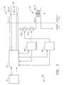
- the new detection system uses the physical breaking of an electrical circuit that includes redundant wiring and associated electronics to detect a turbine engine broken shaft.
- Gas turbine engines generally include rotating shafts having compressor rotors driven by turbine rotors and other elements attached thereto.
- the engine shaft in operation rotates at high speed in a turbine having limited tolerance for longitudinal motion of the shaft and its components. If there is an engine failure which allows axial longitudinal motion of the shaft relative to other engine elements the detection of such motion may be used to activate the shut off of the engine thereby minimizing further damage to the engine and preventing turbine overspeed which, for a gas turbine engine such as on an aircraft, may be catastrophic.
- the shaft breakage may result from bearing failure, imbalance, or other reasons.
- This system requires use of active electro-optical components, such as, light emitting diodes and light activated diodes, near the turbine or use of optical wave-guides and other components for sensing and transmitting. Use of such components in or near the turbine is undesirable as the turbo machinery represents an inhospitable environment for such equipment that may result in sensor failure and false indication of engine failure.
- electromechanical switches to detect compressor failure has been disclosed in U.S. Patent No. 3,612,710 . While this invention discloses a primarily mechanical switch with electrical continuity/discontinuity features, it is complex in operation, which may lead to failure of the sensor and false indication of compressor condition. There is no provision to distinguish an open circuit due to the rotor or impeller movement from a failure of the electrical circuit elements.
- An improved gas turbine engine broken shaft detection system comprises a redundant electrical circuit closed by a breakable wire link in communication with detection and control elements for shut off of a gas turbine engine in the event of rotor shaft failure as for example a broken shaft.
- a broken shaft detection system for use with a gas turbine engine, for detecting axial shaft motion, the system comprising:
Landscapes
- Engineering & Computer Science (AREA)
- Mechanical Engineering (AREA)
- General Engineering & Computer Science (AREA)
- Control Of Turbines (AREA)
- Testing Of Engines (AREA)
Abstract
Claims (9)
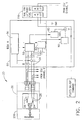
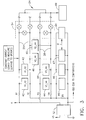
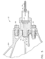
- Système de détection de rupture d'arbre (10) destiné à être utilisé avec un moteur de turbine à gaz (200), pour la détection d'un mouvement d'arbre axial, le système comprenant :un élément de détection de rupture d'arbre (20) pourvu d'un ensemble détecteur (22) comportant un piston (30) à côté d'une liaison (24), dans lequel le piston (30) est à même d'être déplacé dans le sens axial, en fonctionnement, par le mouvement d'arbre axial, brisant de ce fait la liaison (24) ;une unité de commande électronique (50) à même de permettre la coupure du moteur (200) lors de la rupture de la liaison (24), etune source d'alimentation électrique (12);caractérisé en ce que :l'unité de commande électronique (50) inclut un élément de détection et d'essai (52) qui est en communication électrique avec la liaison (24) de manière à être à même de détecter la rupture de la liaison ;le système de détection de rupture d'arbre (10) comprend en outre un premier circuit, comportant une première paire de fils parallèles (26), et un deuxième circuit, comportant une deuxième paire de fils parallèles (28), les première (26) et deuxième (28) paires de fils parallèles étant connectées à l'élément de détection et d'essai (52) de sorte que l'unité de commande électronique (50) est à même de surveiller la continuité dans chacun des premier et deuxième circuits ;une extrémité de la liaison (24) est rattachée à une extrémité de la première paire de fils parallèles (26) et l'autre extrémité de la liaison (24) est rattachée à une extrémité de la deuxième paire de fils parallèles (28), de sorte que la liaison (24) assure la continuité du circuit entre les paires de fils parallèles (26, 28) ;la source d'alimentation électrique (12) est électriquement connectée à l'autre extrémité de la première paire de fils parallèles (26) et à l'autre extrémité de la deuxième paire de fils parallèles (28) ;l'élément de détection et d'essai (52) est en communication électrique avec un circuit de sortie (80) de manière à être à même de communiquer au circuit de sortie (80) que la liaison (24) a été rompue pour amener le circuit de sortie (80) à commander un commutateur de coupure (100), etl'élément de détection et d'essai (52) est configuré pour communiquer que la liaison (24) a été rompue uniquement si l'unité de commande électronique (50) détecte que le premier circuit et le deuxième circuit sont tous deux continus.
- Système suivant la revendication 1, dans lequel chaque fil de la paire de fils (26, 28) est acheminé à travers un commutateur à isolation optique (54) dans l'unité de commande électronique (50) et les commutateurs à isolation optique (54) sont commandés par une unité centrale (56).
- Système suivant la revendication 1 ou 2, dans lequel la première paire de fils parallèles (26, 28) est scindée pour former la deuxième paire de fils parallèles (26, 28), la deuxième paire de fils parallèles étant acheminée jusqu'à un deuxième élément de détection et d'essai (52).
- Système suivant la revendication 1 ou 2, comprenant en outre un deuxième élément de détection et d'essai (52) en communication électrique avec la liaison (24), et un deuxième circuit de sortie (80) en communication électrique avec le deuxième élément de détection et d'essai (52).
- Système suivant l'une quelconque des revendications précédentes, dans lequel un des éléments de détection et d'essai (52) au moins comprend :(I) une paire de comparateurs de tension (40) connectés entre les deux paires de fils parallèles (26, 28) ;(II) une paire de comparateurs de tension doubles (42) connectés entre chaque fil des paires de fils parallèles (26, 28) ;(III) une paire de circuits de surveillance de courant (45, 46) et une paire de circuits de surveillance de puissance (47, 48) connectés pour mesurer les niveaux de courant et de puissance, ou(IV) un élément de fuite de tension (49) connecté pour mesurer la fuite vers la masse.
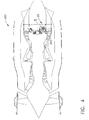
- Système suivant l'une quelconque des revendications précédentes, dans lequel l'ensemble détecteur (22) est monté dans une turbine à gaz (200) en aval d'une roue de turbine de puissance du troisième étage (202).
- Système suivant l'une quelconque des revendications précédentes, dans lequel le piston (30) est enfermé dans un capot de piston (32).
- Système suivant l'une quelconque des revendications précédentes, le système comprenant en outre une soupape d'arrêt (110) activée par le commutateur de coupure (100).
- Système suivant la revendication 1, dans lequel l'unité de commande électronique (50) est à même de détecter un circuit ouvert dans l'une parmi la première paire de fils parallèles (26) et la deuxième paire de fils parallèles (28), ou les deux, que la liaison (24) soit rompue ou non.
Applications Claiming Priority (3)
| Application Number | Priority Date | Filing Date | Title |
|---|---|---|---|
| US992847 | 2001-11-14 | ||
| US09/992,847 US6607349B2 (en) | 2001-11-14 | 2001-11-14 | Gas turbine engine broken shaft detection system |
| PCT/US2002/036197 WO2003093652A2 (fr) | 2001-11-14 | 2002-11-12 | Systeme de detection de rupture d'arbre dans une turbine a gaz |
Publications (2)
| Publication Number | Publication Date |
|---|---|
| EP1451448A2 EP1451448A2 (fr) | 2004-09-01 |
| EP1451448B1 true EP1451448B1 (fr) | 2008-01-09 |
Family
ID=25538804
Family Applications (1)
| Application Number | Title | Priority Date | Filing Date |
|---|---|---|---|
| EP02806840A Expired - Lifetime EP1451448B1 (fr) | 2001-11-14 | 2002-11-12 | Systeme de detection de rupture d'arbre dans une turbine a gaz |
Country Status (6)
| Country | Link |
|---|---|
| US (1) | US6607349B2 (fr) |
| EP (1) | EP1451448B1 (fr) |
| AU (1) | AU2002367914A1 (fr) |
| CA (1) | CA2467710C (fr) |
| DE (1) | DE60224570T2 (fr) |
| WO (1) | WO2003093652A2 (fr) |
Families Citing this family (39)
| Publication number | Priority date | Publication date | Assignee | Title |
|---|---|---|---|---|
| DE10310900A1 (de) * | 2003-03-13 | 2004-09-23 | Rolls-Royce Deutschland Ltd & Co Kg | Elekronisches Sicherheitssystem zur Vermeidung eines Überdrehzahlzustandes bei einem Wellenbruch |
| DE102004009595A1 (de) * | 2004-02-27 | 2005-09-15 | Mtu Aero Engines Gmbh | Verfahren und Vorrichtung zur Identifikation eines Wellenbruchs und/oder einer Überdrehzahl an einer Gasturbine |
| DE102004026366A1 (de) * | 2004-05-29 | 2005-12-15 | Mtu Aero Engines Gmbh | Einrichtung zur Detektion eines Wellenbruchs an einer Gasturbine sowie Gasturbine |
| DE102004033266A1 (de) * | 2004-07-09 | 2006-02-02 | Dr. Johannes Heidenhain Gmbh | Positionsmesseinrichtung und Verfahren zur Positionsmessung |
| DE102004033924A1 (de) * | 2004-07-14 | 2006-02-09 | Mtu Aero Engines Gmbh | Einrichtung zur Detektion eines Wellenbruchs an einer Gasturbine sowie Gasturbine |
| DE102004047892A1 (de) * | 2004-10-01 | 2006-04-06 | Mtu Aero Engines Gmbh | Gasturbine und Verfahren zum Abschalten einer Gasturbine bei Identifikation eines Wellenbruchs |
| US7703270B2 (en) * | 2005-07-15 | 2010-04-27 | Pratt & Whitney Canada Corp. | Cable connection for a gas turbine engine safety fuel shut-off mechanism |
| DE102005042271A1 (de) * | 2005-09-06 | 2007-03-08 | Mtu Aero Engines Gmbh | Einrichtung zur Detektion eines Wellenbruchs an einer Gasturbine sowie Gasturbine |
| US7654093B2 (en) * | 2005-09-26 | 2010-02-02 | Pratt & Whitney Canada Corp. | Method of adjusting a triggering clearance and a trigger |
| US7536850B2 (en) * | 2005-09-27 | 2009-05-26 | Pratt & Whitney Canada Corp. | Emergency fuel shutoff system |
| DE102006016011A1 (de) * | 2006-04-05 | 2007-10-18 | Rolls-Royce Deutschland Ltd & Co Kg | Notabschaltdetektorvorrichtung für eine Gasturbine |
| DE102006017790B3 (de) * | 2006-04-15 | 2007-07-26 | Mtu Aero Engines Gmbh | Einrichtung zur Detektion eines Wellenbruchs an einer Gasturbine sowie Gasturbine |
| FR2907839B1 (fr) * | 2006-10-25 | 2011-06-17 | Snecma | Methode pour reduire la vitesse en cas de rupture d'arbre de turbine de moteur a turbine a gaz |
| FR2923540B1 (fr) * | 2007-11-13 | 2010-01-29 | Snecma | Dispositif de detection de rupture d'un arbre de turbomachine |
| US9355571B2 (en) * | 2008-01-23 | 2016-05-31 | Sikorsky Aircraft Corporation | Modules and methods for biasing power to a multi-engine power plant suitable for one engine inoperative flight procedure training |
| GB2468686A (en) * | 2009-03-18 | 2010-09-22 | Weston Aerospace Ltd | System and method for detecting abnormal movement in a gas turbine shaft |
| US9169742B2 (en) * | 2010-02-26 | 2015-10-27 | Pratt & Whitney Canada Corp. | Electronic shaft shear detection conditioning circuit |
| US8866334B2 (en) | 2010-03-02 | 2014-10-21 | Icr Turbine Engine Corporation | Dispatchable power from a renewable energy facility |
| US8984895B2 (en) | 2010-07-09 | 2015-03-24 | Icr Turbine Engine Corporation | Metallic ceramic spool for a gas turbine engine |
| GB2488805A (en) * | 2011-03-09 | 2012-09-12 | Rolls Royce Plc | Shaft break detection |
| US9051873B2 (en) | 2011-05-20 | 2015-06-09 | Icr Turbine Engine Corporation | Ceramic-to-metal turbine shaft attachment |
| GB2494703B (en) | 2011-09-16 | 2016-08-03 | Weston Aerospace Ltd | System and method for detecting abnormal movement in a gas turbine shaft |
| US10094288B2 (en) | 2012-07-24 | 2018-10-09 | Icr Turbine Engine Corporation | Ceramic-to-metal turbine volute attachment for a gas turbine engine |
| US10167784B2 (en) * | 2012-10-26 | 2019-01-01 | Pratt & Whitney Canada Corp. | System for detecting shaft shear event |
| US10190440B2 (en) * | 2015-06-10 | 2019-01-29 | Rolls-Royce North American Technologies, Inc. | Emergency shut-down detection system for a gas turbine |
| GB2539405A (en) * | 2015-06-15 | 2016-12-21 | Weston Aerospace Ltd | System for detecting abnormal movement of a shaft in a gas turbine engine |
| GB2540784A (en) * | 2015-07-27 | 2017-02-01 | Weston Aerospace Ltd | Magnetic sensor system for detecting abnormal movement in a gas turbine shaft |
| CN105257346A (zh) * | 2015-11-13 | 2016-01-20 | 中国船舶重工集团公司第七�三研究所 | 一种船舶主汽轮机控制方式切换装置 |
| US10989063B2 (en) | 2016-08-16 | 2021-04-27 | Honeywell International Inc. | Turbofan gas turbine engine shaft break detection system and method |
| EP3330493B1 (fr) * | 2016-12-02 | 2019-05-01 | Rolls-Royce Deutschland Ltd & Co KG | Système de commande et procédé pour moteur de turbine à gaz |
| US10319207B1 (en) * | 2017-02-02 | 2019-06-11 | Briggs & Stratton Corporation | Portable generator including carbon monoxide detector |
| WO2018183506A1 (fr) | 2017-03-28 | 2018-10-04 | Briggs & Stratton Corporation | Générateur portatif comprenant un détecteur de monoxyde de carbone |
| WO2018183879A1 (fr) | 2017-03-31 | 2018-10-04 | Generac Power Systems, Inc. | Système de détection de monoxyde de carbone pour machines à moteur à combustion interne |
| US11067556B1 (en) | 2017-05-30 | 2021-07-20 | Briggs & Stratton, Llc | Carbon monoxide sensor for portable generator |
| US10683810B2 (en) | 2017-12-01 | 2020-06-16 | Pratt & Whitney Canada Corp. | Shaft shear detection for gas turbine engines |
| US11401825B2 (en) | 2018-10-29 | 2022-08-02 | Rolls-Royce Deutschland Ltd & Co Kg | Gas turbine engine control system and method for limiting turbine overspeed in case of a shaft failure |
| GB2583078B (en) | 2019-04-09 | 2022-10-05 | Weston Aerospace Ltd | System for detecting abnormal movement of a shaft in a gas turbine engine |
| CN115112374B (zh) * | 2021-03-23 | 2025-02-28 | 中国航发商用航空发动机有限责任公司 | 断轴装置和断轴模拟系统 |
| CN115626451A (zh) * | 2022-10-28 | 2023-01-20 | 新兴铸管股份有限公司 | 一种第一时间断轴报警保护装置 |
Family Cites Families (18)
| Publication number | Priority date | Publication date | Assignee | Title |
|---|---|---|---|---|
| DE1122550B (de) * | 1956-04-13 | 1962-01-25 | Gen Electric | Hydraulische Einrichtung zur UEberwachung des Laeufers einer Kreiselmaschine auf Axialverschiebung |
| GB837309A (en) * | 1956-11-08 | 1960-06-09 | Rolls Royce | Improvements in or relating to gas-turbine engines |
| US2930189A (en) | 1957-04-08 | 1960-03-29 | Rolls Royce | Gas turbine engine with shaft-failure control |
| US3097824A (en) | 1958-11-26 | 1963-07-16 | Bendix Corp | Turbine, wheel containment |
| US2976012A (en) | 1959-02-19 | 1961-03-21 | Gen Electric | Turbine overspeed protective system |
| US3050939A (en) | 1960-05-05 | 1962-08-28 | Rolls Royce | Gas turbine engine with shaft failure control |
| US3159166A (en) | 1961-10-16 | 1964-12-01 | Gen Motors Corp | Engine safety control |
| US3550108A (en) * | 1968-05-06 | 1970-12-22 | Globe Union Inc | Shaft rotation failure system |
| US3568469A (en) * | 1969-06-27 | 1971-03-09 | Avco Corp | System for instantaneously disconnecting a rotating load |
| US3612710A (en) | 1970-04-30 | 1971-10-12 | Carrier Corp | Centrifugal refrigerant gas compressor |
| JPS5274737A (en) | 1975-12-19 | 1977-06-23 | Hitachi Ltd | Operation stopper of hydraulical machinery |
| SU1229563A1 (ru) * | 1983-12-30 | 1986-05-07 | Казанский компрессорный завод | Сигнализатор перемещени ротора компрессора |
| GB2181246B (en) | 1985-10-02 | 1989-09-27 | Rolls Royce | Apparatus for measuring axial movement of a rotating member |
| GB8706905D0 (en) | 1987-03-24 | 1987-04-29 | Schlumberger Electronics Uk | Shaft monitoring system |
| JPH03121219A (ja) * | 1989-10-03 | 1991-05-23 | Mitsubishi Heavy Ind Ltd | エンジンの緊急停止装置 |
| US5363317A (en) * | 1992-10-29 | 1994-11-08 | United Technologies Corporation | Engine failure monitor for a multi-engine aircraft having partial engine failure and driveshaft failure detection |
| US5411364A (en) | 1993-12-22 | 1995-05-02 | Allied-Signal Inc. | Gas turbine engine failure detection system |
| DE19727296A1 (de) * | 1997-06-27 | 1999-01-07 | Mtu Muenchen Gmbh | Einrichtung zur Notabschaltung einer Gasturbine |
-
2001
- 2001-11-14 US US09/992,847 patent/US6607349B2/en not_active Expired - Lifetime
-
2002
- 2002-11-12 CA CA002467710A patent/CA2467710C/fr not_active Expired - Fee Related
- 2002-11-12 DE DE60224570T patent/DE60224570T2/de not_active Expired - Lifetime
- 2002-11-12 EP EP02806840A patent/EP1451448B1/fr not_active Expired - Lifetime
- 2002-11-12 WO PCT/US2002/036197 patent/WO2003093652A2/fr not_active Ceased
- 2002-11-12 AU AU2002367914A patent/AU2002367914A1/en not_active Abandoned
Also Published As
| Publication number | Publication date |
|---|---|
| DE60224570D1 (de) | 2008-02-21 |
| CA2467710A1 (fr) | 2003-11-13 |
| WO2003093652A2 (fr) | 2003-11-13 |
| WO2003093652A3 (fr) | 2004-06-17 |
| US20030091430A1 (en) | 2003-05-15 |
| CA2467710C (fr) | 2008-05-06 |
| EP1451448A2 (fr) | 2004-09-01 |
| AU2002367914A8 (en) | 2003-11-17 |
| US6607349B2 (en) | 2003-08-19 |
| AU2002367914A1 (en) | 2003-11-17 |
| DE60224570T2 (de) | 2009-01-08 |
Similar Documents
| Publication | Publication Date | Title |
|---|---|---|
| EP1451448B1 (fr) | Systeme de detection de rupture d'arbre dans une turbine a gaz | |
| US4712372A (en) | Overspeed system redundancy monitor | |
| US7246024B2 (en) | Sensor malfunction detection system for gas-turbine engine | |
| US10190440B2 (en) | Emergency shut-down detection system for a gas turbine | |
| CA2727221C (fr) | Circuit de conditionnement du detecteur electronique de cisaillement d'arbre de transmission | |
| CN113719359A (zh) | 一种预防航空涡轴发动机涡轮超转破裂的保护方法和系统 | |
| JPS63202217A (ja) | 複数の負荷に電力を供給する回路 | |
| EP2961919B1 (fr) | Unité et système électrique sous-marin | |
| EP3106626B1 (fr) | Système de détection de mouvement anormal d'un arbre dans un moteur à turbine à gaz | |
| JP2877912B2 (ja) | 内燃機関の電子制御装置 | |
| US8026810B2 (en) | Device for controlling and monitoring sequential subsections of an installation | |
| US7719131B2 (en) | Apparatus for monitoring a supply system, in particular a motor-vehicle electrical system, and method for monitoring a supply system of this type | |
| US6707372B2 (en) | Thermal switch containing preflight test feature and fault location detection | |
| US7735310B2 (en) | Gas turbine and method for shutting off a gas turbine when breakage of a shaft is identified | |
| US7581377B2 (en) | Low-cost frangible cable for gas turbine engine | |
| US3981611A (en) | Electrical interconnection circuitry from a rotating body to a relatively stationary body | |
| JP2000194403A (ja) | 車両用負荷診断装置 | |
| CA2929832A1 (fr) | Mecanisme de detection d'arret d'urgence destine a une turbine a gaz | |
| CN101252271A (zh) | 设备的保护系统以及用于检验保护系统的方法 | |
| EP1739438B1 (fr) | Moniteur de vitesse du mécanisme turbo | |
| US20050122201A1 (en) | Thermal switch containing preflight test feature and fault location detection | |
| JPS5993905A (ja) | 回転機の主油ポンプ軸切損時の緊急停止装置 | |
| KR20150012876A (ko) | 전기 자동차의 차륜 제어방법 및 제어시스템 | |
| JP2002276305A (ja) | 蒸気タービン装置 | |
| JPH0229895A (ja) | 異常警報装置 |
Legal Events
| Date | Code | Title | Description |
|---|---|---|---|
| PUAI | Public reference made under article 153(3) epc to a published international application that has entered the european phase |
Free format text: ORIGINAL CODE: 0009012 |
|
| 17P | Request for examination filed |
Effective date: 20040604 |
|
| AK | Designated contracting states |
Kind code of ref document: A2 Designated state(s): AT BE BG CH CY CZ DE DK EE ES FI FR GB GR IE IT LI LU MC NL PT SE SK TR |
|
| AX | Request for extension of the european patent |
Extension state: AL LT LV MK RO SI |
|
| RIN1 | Information on inventor provided before grant (corrected) |
Inventor name: JONES, KEVIN, A. Inventor name: STEVENS, PAUL, M. Inventor name: FAYMON, DAVE, K. Inventor name: MULERA, TOM, G. |
|
| 17Q | First examination report despatched |
Effective date: 20050217 |
|
| GRAP | Despatch of communication of intention to grant a patent |
Free format text: ORIGINAL CODE: EPIDOSNIGR1 |
|
| GRAS | Grant fee paid |
Free format text: ORIGINAL CODE: EPIDOSNIGR3 |
|
| GRAA | (expected) grant |
Free format text: ORIGINAL CODE: 0009210 |
|
| AK | Designated contracting states |
Kind code of ref document: B1 Designated state(s): DE FR GB |
|
| REG | Reference to a national code |
Ref country code: GB Ref legal event code: FG4D |
|
| REF | Corresponds to: |
Ref document number: 60224570 Country of ref document: DE Date of ref document: 20080221 Kind code of ref document: P |
|
| ET | Fr: translation filed | ||
| PLBE | No opposition filed within time limit |
Free format text: ORIGINAL CODE: 0009261 |
|
| STAA | Information on the status of an ep patent application or granted ep patent |
Free format text: STATUS: NO OPPOSITION FILED WITHIN TIME LIMIT |
|
| 26N | No opposition filed |
Effective date: 20081010 |
|
| PGFP | Annual fee paid to national office [announced via postgrant information from national office to epo] |
Ref country code: DE Payment date: 20091130 Year of fee payment: 8 |
|
| PGFP | Annual fee paid to national office [announced via postgrant information from national office to epo] |
Ref country code: FR Payment date: 20091120 Year of fee payment: 8 Ref country code: GB Payment date: 20091007 Year of fee payment: 8 |
|
| GBPC | Gb: european patent ceased through non-payment of renewal fee |
Effective date: 20101112 |
|
| REG | Reference to a national code |
Ref country code: FR Ref legal event code: ST Effective date: 20110801 |
|
| REG | Reference to a national code |
Ref country code: DE Ref legal event code: R119 Ref document number: 60224570 Country of ref document: DE Effective date: 20110601 Ref country code: DE Ref legal event code: R119 Ref document number: 60224570 Country of ref document: DE Effective date: 20110531 |
|
| PG25 | Lapsed in a contracting state [announced via postgrant information from national office to epo] |
Ref country code: FR Free format text: LAPSE BECAUSE OF NON-PAYMENT OF DUE FEES Effective date: 20101130 |
|
| PG25 | Lapsed in a contracting state [announced via postgrant information from national office to epo] |
Ref country code: GB Free format text: LAPSE BECAUSE OF NON-PAYMENT OF DUE FEES Effective date: 20101112 |
|
| PG25 | Lapsed in a contracting state [announced via postgrant information from national office to epo] |
Ref country code: DE Free format text: LAPSE BECAUSE OF NON-PAYMENT OF DUE FEES Effective date: 20110531 |
|
| P01 | Opt-out of the competence of the unified patent court (upc) registered |
Effective date: 20230525 |