EP1451605B1 - Kalibrierter echtzeittakt zur erfassung von gps-signalen während des betriebs mit geringer stromaufnahme - Google Patents
Kalibrierter echtzeittakt zur erfassung von gps-signalen während des betriebs mit geringer stromaufnahme Download PDFInfo
- Publication number
- EP1451605B1 EP1451605B1 EP02776367A EP02776367A EP1451605B1 EP 1451605 B1 EP1451605 B1 EP 1451605B1 EP 02776367 A EP02776367 A EP 02776367A EP 02776367 A EP02776367 A EP 02776367A EP 1451605 B1 EP1451605 B1 EP 1451605B1
- Authority
- EP
- European Patent Office
- Prior art keywords
- gps
- oscillator
- time
- low power
- signal
- Prior art date
- Legal status (The legal status is an assumption and is not a legal conclusion. Google has not performed a legal analysis and makes no representation as to the accuracy of the status listed.)
- Expired - Lifetime
Links
Images



Classifications
-
- G—PHYSICS
- G04—HOROLOGY
- G04G—ELECTRONIC TIME-PIECES
- G04G19/00—Electric power supply circuits specially adapted for use in electronic time-pieces
- G04G19/12—Arrangements for reducing power consumption during storage
-
- G—PHYSICS
- G01—MEASURING; TESTING
- G01S—RADIO DIRECTION-FINDING; RADIO NAVIGATION; DETERMINING DISTANCE OR VELOCITY BY USE OF RADIO WAVES; LOCATING OR PRESENCE-DETECTING BY USE OF THE REFLECTION OR RERADIATION OF RADIO WAVES; ANALOGOUS ARRANGEMENTS USING OTHER WAVES
- G01S19/00—Satellite radio beacon positioning systems; Determining position, velocity or attitude using signals transmitted by such systems
- G01S19/01—Satellite radio beacon positioning systems transmitting time-stamped messages, e.g. GPS [Global Positioning System], GLONASS [Global Orbiting Navigation Satellite System] or GALILEO
- G01S19/13—Receivers
- G01S19/34—Power consumption
-
- G—PHYSICS
- G01—MEASURING; TESTING
- G01S—RADIO DIRECTION-FINDING; RADIO NAVIGATION; DETERMINING DISTANCE OR VELOCITY BY USE OF RADIO WAVES; LOCATING OR PRESENCE-DETECTING BY USE OF THE REFLECTION OR RERADIATION OF RADIO WAVES; ANALOGOUS ARRANGEMENTS USING OTHER WAVES
- G01S19/00—Satellite radio beacon positioning systems; Determining position, velocity or attitude using signals transmitted by such systems
- G01S19/01—Satellite radio beacon positioning systems transmitting time-stamped messages, e.g. GPS [Global Positioning System], GLONASS [Global Orbiting Navigation Satellite System] or GALILEO
- G01S19/13—Receivers
-
- G—PHYSICS
- G01—MEASURING; TESTING
- G01S—RADIO DIRECTION-FINDING; RADIO NAVIGATION; DETERMINING DISTANCE OR VELOCITY BY USE OF RADIO WAVES; LOCATING OR PRESENCE-DETECTING BY USE OF THE REFLECTION OR RERADIATION OF RADIO WAVES; ANALOGOUS ARRANGEMENTS USING OTHER WAVES
- G01S19/00—Satellite radio beacon positioning systems; Determining position, velocity or attitude using signals transmitted by such systems
- G01S19/01—Satellite radio beacon positioning systems transmitting time-stamped messages, e.g. GPS [Global Positioning System], GLONASS [Global Orbiting Navigation Satellite System] or GALILEO
- G01S19/13—Receivers
- G01S19/23—Testing, monitoring, correcting or calibrating of receiver elements
-
- G—PHYSICS
- G01—MEASURING; TESTING
- G01S—RADIO DIRECTION-FINDING; RADIO NAVIGATION; DETERMINING DISTANCE OR VELOCITY BY USE OF RADIO WAVES; LOCATING OR PRESENCE-DETECTING BY USE OF THE REFLECTION OR RERADIATION OF RADIO WAVES; ANALOGOUS ARRANGEMENTS USING OTHER WAVES
- G01S19/00—Satellite radio beacon positioning systems; Determining position, velocity or attitude using signals transmitted by such systems
- G01S19/01—Satellite radio beacon positioning systems transmitting time-stamped messages, e.g. GPS [Global Positioning System], GLONASS [Global Orbiting Navigation Satellite System] or GALILEO
- G01S19/13—Receivers
- G01S19/23—Testing, monitoring, correcting or calibrating of receiver elements
- G01S19/235—Calibration of receiver components
-
- G—PHYSICS
- G04—HOROLOGY
- G04C—ELECTROMECHANICAL CLOCKS OR WATCHES
- G04C10/00—Arrangements of electric power supplies in time-pieces
- G04C10/04—Arrangements of electric power supplies in time-pieces with means for indicating the condition of the power supply
-
- G—PHYSICS
- G04—HOROLOGY
- G04F—TIME-INTERVAL MEASURING
- G04F5/00—Apparatus for producing preselected time intervals for use as timing standards
-
- G—PHYSICS
- G06—COMPUTING OR CALCULATING; COUNTING
- G06F—ELECTRIC DIGITAL DATA PROCESSING
- G06F1/00—Details not covered by groups G06F3/00 - G06F13/00 and G06F21/00
- G06F1/04—Generating or distributing clock signals or signals derived directly therefrom
- G06F1/14—Time supervision arrangements, e.g. real time clock
-
- G—PHYSICS
- G06—COMPUTING OR CALCULATING; COUNTING
- G06F—ELECTRIC DIGITAL DATA PROCESSING
- G06F1/00—Details not covered by groups G06F3/00 - G06F13/00 and G06F21/00
- G06F1/26—Power supply means, e.g. regulation thereof
- G06F1/32—Means for saving power
- G06F1/3203—Power management, i.e. event-based initiation of a power-saving mode
-
- Y—GENERAL TAGGING OF NEW TECHNOLOGICAL DEVELOPMENTS; GENERAL TAGGING OF CROSS-SECTIONAL TECHNOLOGIES SPANNING OVER SEVERAL SECTIONS OF THE IPC; TECHNICAL SUBJECTS COVERED BY FORMER USPC CROSS-REFERENCE ART COLLECTIONS [XRACs] AND DIGESTS
- Y02—TECHNOLOGIES OR APPLICATIONS FOR MITIGATION OR ADAPTATION AGAINST CLIMATE CHANGE
- Y02D—CLIMATE CHANGE MITIGATION TECHNOLOGIES IN INFORMATION AND COMMUNICATION TECHNOLOGIES [ICT], I.E. INFORMATION AND COMMUNICATION TECHNOLOGIES AIMING AT THE REDUCTION OF THEIR OWN ENERGY USE
- Y02D10/00—Energy efficient computing, e.g. low power processors, power management or thermal management
Definitions
- This invention is generally related to Global Positioning System (GPS) receivers. More particularly, it is related to maintaining an accurate GPS receiver clock circuit during periods of low power operation.
- GPS Global Positioning System
- the Global Positioning System is a collection of twenty-four earth-orbiting satellites. Each of the GPS satellites travels in a precise orbit about 11,000 miles above the earth's surface. A GPS receiver locks onto at least three of the satellites to determine its precise location. Each satellite transmits a signal modulated with a unique pseudo-noise (PN) code. Each PN code is a sequence of 1023 chips that are repeated every ms consistent with a chip rate of 1.023 megahertz (MHz). Each satellite transmits at the same frequency. For civil applications, the frequency is known as L1 and is 1575.42 MHz.
- the GPS receiver receives a signal that is a mixture of the transmissions of the satellites that are visible to the receiver.
- the receiver detects the transmission of a particular satellite by correlating the received signal with shifted versions of the PN code for that satellite. If the level of correlation is sufficiently high so that there is a peak in the level of correlation achieved for a particular shift and PN code, the receiver detects the transmission of the satellite corresponding to the particular PN code. The receiver then uses the shifted PN code to achieve synchronization with subsequent transmissions from the satellite.
- GPS employs a unique time keeping system. GPS time is kept in terms of seconds and weeks since January 6, 1980. There are 604,800 seconds per week. Therefore, GPS time is stated in terms of a time of week (TOW) and a week number. TOW ranges from 0 to 604800, corresponding to the number of seconds in a week. The week number started with week zero on January 6, 1980 and is currently in excess of one thousand weeks.
- TOW time of week
- the TOW can have a fractional part, particularly when oscillators provide a resolution of 1/32,768 th of a second (oscillation frequency of 32 kilo-Hertz, or kHz) or when the GPS time is computed from range measurements relative to a specific clock epoch and can have accuracy on the order of a few tens of nanoseconds. GPS time is fundamental to the GPS system.
- a "cold start” process is initiated whereby the GPS receiver unit searches for all satellites over a wide range of possible frequencies since the GPS receiver begins the acquisition process without knowledge of GPS time, GPS position or ephemeris data for the GPS satellite orbits. In some situations, almanac data is also unknown for the GPS satellites. Eventually, after many seconds, at least four satellite signals are acquired. The satellites' PN encoded signals identify each of the satellites and each satellite transmits precise orbital information (orbital location as a function of GPS time) for that satellite, known as ephemeris data.
- a "warm start” process may be used if almanac data, approximate GPS time and approximate receiver position allow approximate satellite locations and Doppler shifts to be calculated.
- a "hot start” process may be used if the ephemeris, approximate GPS time and approximate receiver position are known so that approximate satellite locations and Doppler shifts can be calculated and the time to collect ephemeris data can be avoided.
- a complete six-second sub-frame of data from at least one satellite is required in order to establish time accurately enough to compute a navigation solution (position).
- the GPS receiver unit determines its distance from each satellite by determining the code phase of the transmission from each satellite.
- the code phase is the delay, in terms of chips or fractions of chips, that a satellite transmission experiences as it travels the approximately 11,000-mile distance from the satellite to the receiver.
- the time of transmission of each PN chip is controlled down to a few nanoseconds. Consequently, knowledge of precise GPS time allows the GPS receiver unit to know exactly what chip of a satellite's waveform is being transmitted at any given time. If the arrival of a given chip at a receiver is measured relative to a local timing epoch, such as the T20, then the propagation time of that chip from the satellite to the GPS receiver unit can be measured as accurately as GPS time at that T20 epoch is known. If the propagation times from each of four satellites are measured relative to the same T20 epoch, then the GPS receiver unit can solve for the location of the receiver in three-dimensional space, along with the error in the value of GPS time at the reference T20.
- the GPS receiver unit precisely determines the distance to the satellite by multiplying the time delay by the velocity of the transmission from the satellite.
- the GPS receiver unit also knows the precise orbits of each of the satellites. Updates of the locations of the satellites are transmitted to the receiver by each of the satellites. This is accomplished by modulating a low frequency (50 Hz) data signal onto the PN code transmission from the satellite.
- the data signal encodes the time-dependent positional information for the satellite and the time errors in its on-board clock in the ephemeris data sub-frames. Precise time of each satellite's transmission is given in each six-second data sub-frame relative to a reference chip at the start of the next sub-frame.
- the receiver uses the estimated range from a satellite to define a sphere around the satellite upon which the receiver must be located.
- the radius of the sphere is equal to to the range to the satellite the receiver has determined from the code phase.
- the receiver performs this process for at least three satellites.
- the receiver derives its precise location from the points of intersection between the at least three spheres it has defined. Measurements from three satellites are sufficient if the receiver knows the altitude at its location. When the altitude is unknown, measurements from four satellites are required so that altitude can also be solved for, along with latitude, longitude and the error in the local clock measurement epoch (e.g., GPS time at the T20 epoch).
- epoch e.g., GPS time at the T20 epoch
- the detection of the signals from each satellite can be accomplished in accordance with a GPS signal detector that is disclosed in, for example, but not limited to, U.S. patent application entitled “SIGNAL DETECTOR EMPLOYING COHERENT INTEGRATION,” having Serial No. 09/281,566, filed on March 30, 1999 .
- a signal detector as disclosed therein may use a correlation mechanism, for example, a matched filter, and a coherent integration scheme in which to detect the appropriate satellite signals.
- Portable GPS receiver units may be designed such that selected components may be shut off, or powered down, during periods when the user is not querying the GPS receiver unit for location information. When the user (or an automated process) queries the GPS receiver unit, the GPS receiver unit reactivates the powered down components and reacquires satellite data to determine the current location.
- the GPS oscillator and timing system must maintain accuracy of the various clocking signals in the GPS receiver unit to better than 0.5 ms (ms) to avoid losing track of which PN code period within the overall GPS signal structure the receiver expects to receive at reacquisition.
- This 0.5 ms criterion corresponds to one half of a 1 ms code period.
- movement of the GPS receiver unit introduces error that may be equated to timing of the PN code signals.
- the time consuming and power consuming process of determining location using the hot, warm or cold start procedures may be avoided because the GPS receiver unit matching filters can immediately lock onto the four previously acquired satellite PN code signals and know which PN code period of the signal structure has been acquired. Otherwise, the hot, warm or cold start procedures must be used, depending on the prior information (almanac, ephemeris, GPS time, receiver position) that has been preserved while the receiver was off.
- a conventional real time clock (RTC) circuit may be used to maintain rough GPS time while the rest of the GPS circuitry if off.
- Typical RTC circuits may maintain accuracy of a few seconds over extended periods. Such accuracy is adequate for hot and warm starts.
- the accuracy of a conventional real time clock degrades rapidly due to poor stability and temperature characteristics of typical low cost, low power RTC circuits. Therefore, even after a very brief time, a cold start is required.
- Maintaining accuracy of the various clocking signals in the GPS receiver unit to within ⁇ 0.5 ms (one half of a 1 ms code period) is not possible with a conventional GPS oscillator and timing system if the oscillator is powered down between navigation updates.
- the GPS oscillator and the associated timing system consume significant power, powering down these components is very desirable in a portable GPS receiver unit to conserve power resources.
- US-A-5 629 708 and US-A-5 864 315 disclose a system and a method according to the preambles of claims 1 and 11.
- GPS Global Positioning System
- a K32 (typically a nominal 32,768 Hz) oscillator residing in a low power time keeping circuit accurately preserves GPS time when the selected components are shut off.
- a local GPS oscillator crystal generates an M11 clock signal that is used to accurately determine GPS time based upon signals detected from the plurality of satellites.
- An edge aligned ratio counter continuously monitors the K32 and M11 clock signals with free running counters, and when an edge of the K32 clock signal aligns with an edge of an M11 signal, within a predetermined small tolerance, the K32 and M11 counter values are latched. At the time of latching, the edge aligned ratio counter provides a signal to the local GPS clocks generator so that a specific T20 timing epoch is related to the K23 and M11 counter values.
- the GPS receiver unit 100 is able to correlate the timing and the rates of the K32 clock signal and the GPS M11 clock signal with the T20 timing epoch.
- the correlated timing and rates of the K32 clock signal, the GPS M11 clock signal and the T20 epoch are provided to the Navigation processor so that a sufficiently accurate estimate of GPS time at a T20 epoch is calculated to allow determination of the PN code periods in the signal structures of acquires satellite PN code signals.
- frequencies of the local GPS oscillator crystal and the K32 oscillator are detected at various operating temperatures such that a temperature frequency table is defined for both oscillators.
- the data for both temperature frequency tables are stored in a memory.
- Selected components residing the GPS receiver unit, including the GPS oscillator, are then shut down (deactivated) to conserve power.
- the low power time keeping circuit remains on. Periodically, after a predetermined period of time, the system is repowered (activated) in response to a wake-up command generated by an alarm unit.
- the K32 clock signal from the low power time keeping circuit is recalibrated based upon the actual operating temperature of the K32 oscillator and data from the K32 clock temperature/frequency table. Thus, the K32 clock rate is periodically updated to more accurately track GPS time.
- a navigation update is performed in accordance with the requirements of the particular system application.
- the periodically recalibrated K32 clock signal and data from the GPS clock temperature/frequency table are used to set the M11 clock signal rate and GPS time. Positions of the GPS satellites are then estimated such that the real GPS time can be quickly determined from the received satellite signals.
- the M11 and K32 signals are latched together and correlated with the real GPS time at a T20 epoch, as described above, to further improve and update their temperature calibration tables. The selected components are then shut off once again to conserve power.
- the process described above is repeated as necessary so that accurate GPS time is maintained by the low power time keeping circuit
- the GPS receiver unit more quickly determines position from the GPS satellites because the GPS satellite positions and ranges are estimated with a high degree of precision based on the more accurate time keeping. That is, the power consuming and time consuming process of detecting sub-frame data and determining sub-frame timing to set the GPS time accurately enough to estimate the ranges to the GPS satellites using conventional processes is avoided.
- FIG. 1 illustrates an example environment for operation of a global positioning system (GPS) receiver.
- FIG. 1 shows a GPS receiver unit 100 and four GPS satellites 102, 104, 106 and 108. Each satellite 102, 104, 106 and 108 is transmitting to the GPS receiver unit 100.
- Satellite 102 is moving towards the GPS receiver unit 100 along the line of sight (LOS) 110 at a velocity v a + ;
- satellite 104 is moving away from the GPS receiver unit 100 along the LOS 112 at a velocity v b - ;
- satellite 106 is moving away from the GPS receiver unit 100 along the LOS 106 at a velocity v c - .
- LOS line of sight
- the transmission from satellite 102 experiences a positive Doppler shift of v a + ⁇ ; the transmission from satellite 104 experiences a negative Doppler shift of v b - ⁇ ; and the transmission from satellite 106 experiences a negative Doppler shift of v c - ⁇ .
- Satellite 108 is similarly moving away from the GPS receiver unit 100 along the LOS 116 at a velocity v d - .
- Information provided by the fourth satellite 116 may be used in some applications to determine the error in the altitude value of the receiver if it is not known beforehand.
- the four satellites must have adequate geometry in order to provide measurements capable of solving for latitude, longitude, altitude and time error. Range measurements from more than the minimum quantity of four visible satellites may be required to solve for the four unknown quantities when satellite geometry is poor.
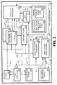
- FIG. 2 is a block diagram illustrating selected components of a GPS receiver unit 100 having a low power time keeping circuit 200.
- GPS receiver unit 100 includes at least a radio 202, local GPS oscillator 204, temperature sensor 206, a plurality of GPS signal processor channels 208 (1 through N), navigation processor 210, matched filter 212, A/D converter 214, local GPS clocks generator 216, edge aligned ratio counter 218, memory 220 and low power time keeping circuit 200.
- Memory 220 further includes the wake-up alarm logic 222 and an allocated portion for the GPS clock Low Power Time Keeping (LPTK) Circuit error temperature/frequency error table 224.
- FIG. 2 is generally limited to illustrating those components relevant to the operation and functioning of the invention. Other components, not shown, are included in the GPS receiver unit 100. These omitted components are not illustrated in FIG. 2 or discussed in detail since the operation and functionality of these omitted components are not necessarily relevant to the invention.
- LPTK Low Power Time Keeping
- Radio 202 detects a plurality of GPS signals from a plurality of satellites, such as, but not limited to, satellites 102, 104, 106 and 108 ( FIG. 1 ). In one embodiment the radio 202 selects the GPS L1 band (1575.42 MHz), however other embodiments may select other suitable signals. Radio 202 also receives a timing signal from local GPS oscillator 204, via connection 226. The timing signal, in one embodiment, is generated by a crystal (not shown) residing in the local GPS oscillator 204 that oscillates at substantially 10.949 mega-hertz (MHz), and is referred to as the M11 clock signal. Other embodiments may employ a local GPS oscillator operating at a different frequency clock signal without departing substantially from the operation and functionality of the invention.
- the received GPS signals and the M11 timing signal are provided to the plurality of GPS signal processors 208 and matched filter 212.
- Each one of the plurality of GPS signal processors 208 corresponds to a particular signal channel.
- FIG. 2 indicates that there are N GPS signal processors.
- the signal processors 208 and matching filter 212 receive a sequence of pre-positioning commands from the navigation processor 210, via connection 230, that estimates the specific GPS PN code that each signal processor is to search for.
- Information provided by navigation processor 210 may also include Doppler correction values, GPS oscillator error correction values, PN code phase information and/or other relevant information regarding the incoming satellite signals.
- the matched filter 212 determines the current PN code phase of a detected signal and provides the information to the signal processors 208 to allow the signal processor channel to more rapidly acquire that signal.
- the GPS signal processor synchronizes to and tracks the incoming satellite signal.
- Another embodiment employs only the matched filter 212 to determine position (although with a lesser degree of accuracy since the matched filter 212 determines the current code phase of a signal at a point in time and does not continually track it).
- the matched filter 212 and/or the GPS signal processors 208 provide code phase information regarding the acquired signals to the navigation processor 210, via connections 234 and/or 232, respectively.
- Navigation processor 210 then calculates the position of the GPS receiver unit 100 after sufficient information from at least four GPS satellite signals has been provided by the matched filter 212 and/or the GPS signal processors 208.
- the location information is then output to an interface system (not shown) so that a user may learn of the position of the GPS receiver unit 100.
- the local GPS oscillator 204 provides a signal having a predefined oscillation frequency.
- the oscillation frequency of a crystal (not shown) residing in one embodiment of the local GPS oscillator 204 is configured to equal 10.949296.875 megahertz (MHz).
- the precise nominal value of the oscillation frequency equals 137 F 0 /128.
- F 0 is a fundamental parameter of the GPS system equal to 10.23 MHz.
- the GPS L1 frequency of the received GPS signals is 154 F 0 .
- the chip rate of the Clear/Acquisition GPS PN codes used in commercial systems is F 0 /10.
- One embodiment of the GPS oscillator 204 is referred to as outputting an M11 clocking signal, where the term "M11" corresponds to the 137 F 0 /128 frequency of 10.949296.875 MHz.
- Other signals of the GPS system including frequencies and codes used by military receivers, are also related to F 0 .
- the local GPS oscillator 204 provides the M11 clocking signal, via connection 234, to the local GPS clocks generator 216.
- Local GPS clocks generator 216 derives a plurality of clock signals from the M11 clocking signal. These clocks correspond to the local GPS time-base. Of particular interest, one of the plurality of clocks is known as the local timing epoch, the T20 clock.
- the T20 clock derives its name from the fact that it is 20 ms between clock ticks. Many of the code phases measured in the GPS signal processors 208 and the matched filter 212 are referenced to a common T20 epoch. Selected clocking signals generated by the local GPS clocks generator 216 are provided to the GPS signal processors 208 and the matched filter 212 over connection 236.
- the low power time keeping circuit 200 provides a clocking signal to the edge aligned ratio counter 218, via connection 252.
- the clocking signal rate in one embodiment, is provided by a crystal oscillating at substantially 32.768 kilohertz (kHz), and is referred to as the K32 clock signal.
- the low power time keeping circuit 200 provides information to the navigation processor 210 (connections not shown).
- the information provided to the navigation processor 210 by the low power time keeping circuit 200 is an estimate of the GPS time at a T20 epoch.
- Other embodiments may employ a different frequency clock signal without departing substantially from the operation and functionality of the invention.
- the edge aligned ratio counter 218 provides input to the local GPS clocks generator 216 (via connection 244), to the matched filter 212 (via connection 246), and to the low power time keeping circuit 200 (via connection 248).
- connections 244, 246 and 248 are illustrated as separate connections. However, one or more of these connections could be implemented as a single connection.
- the edge aligned ratio counter 218 also provides information to the navigation processor 210 via connection 250.
- the edge aligned ratio counter 218 continuously counts and monitors the K32 and M11 clock signals, and when an edge of the K32 clock signal aligns with an edge of the M11 signal, within a predetermined small tolerance, the K32 and M11 counter values are latched.
- the edge aligned ratio counter 218 provides a signal to the local GPS clocks generator 216 so that the current T20 clocking count is latched to relate the K32 and M11 counts to the T20 epoch.
- the edge aligned ratio counter 218 provides a signal to the low power time keeping circuit 200, via connection 248, that causes the current low power time keeping circuit 200 estimate of GPS time to be latched.
- the GPS receiver unit 100 is able to correlate the timing and the rates of the K32 clock signal and the GPS M11 clock signal with the T20 epoch and the current low power time keeping circuit 200 GPS time.
- the low power time keeping circuit 200 estimate of GPS time at a T20 epoch can be calculated and the relative rates of these two clocks can be estimated from counter ratios of the two clocks in the edge aligned ratio counter 218.
- two sets of counter values from successive edge alignment events are differenced and the ratios of the differences taken.
- GPS receiver unit 100 is intended as a general description of one system used by an embodiment of a GPS receiver unit. Not all GPS receiver unit components are described or illustrated, as such components may not necessarily relate to the invention. Thus, the description of the above-described components residing in the GPS receiver unit 100 is generally limited to describing the operation and functionality of those components to the extent necessary for the understanding of the invention. Furthermore, a GPS receiver unit or other processor systems employing the invention may have the components shown in FIG. 2 connected in a different order and manner than shown in FIG. 2 , or may not include all of the components shown in FIG. 2 , or may include additional components connected in some manner with the components shown in FIG. 2 . Any such variations in GPS receiver unit or a processor system that utilizes the invention are intended to be within the scope of this disclosure and be protected by the accompanying claims.
- Temperature sensor 206 detects the operating temperature of the local GPS oscillator 204, via connection 238. The sensed temperature information is then provided to the A/D converter 214 over connection 240. A/D converter 214 converts the sensed operating temperature information into a suitable format and provides the information to the navigation processor 210, via connection 242. Temperature sensor 206 and A/D converter 214 may be implemented using well known components and techniques employed in the art of detecting temperatures. The temperature sensing functions performed by temperature sensor 206 and/or A/D converter 214 may be implemented with any type of electronic, solid state and/or firmware type temperature sensors or means commonly employed in the art of sensing temperatures.
- Such a temperature sensor employed in the invention is implemented by a combination of software and firmware using components and techniques commonly employed in the art of sensing temperatures. Detailed operation of temperature sensor 206 and A/D 214, including their individual components, are not described in detail other than to the extent necessary to understand the operation and functioning of invention. One skilled in the art will realize that the temperature sensor 206 and the A/D converter 214 may be implemented using a variety of well known devices without departing substantially from the functionality and operation of the invention.
- Navigation processor 210 processes the received temperature information such that a frequency error in the GPS oscillator signal due to the operating temperature of the local GPS oscillator 204 is determined.
- An exemplary process for determining this frequency error employs a table having temperature and frequency error information for a range of operating temperatures.
- the GPS clock temperature/frequency error table 224 resides in a non-volatile memory 220.
- a frequency/temperature error algorithm such as a polynomial representation of the frequency error as a function of temperature of a typical oscillator crystal, is employed to approximate the temperature related frequency error.
- the portion of the temperature/frequency error table 224 for the GPS clock data is filled with more accurate information of the frequency error at particular operating temperatures for the local GPS oscillator 204 based upon measurements of frequency error based on GPS satellite range and range rate measurements at various operating temperatures.
- Solution of the GPS navigation equations allows a determination of receiver spatial velocity and local oscillator frequency error (rate of change of GPS time error), as well as spatial position and GPS time error.
- the oscillator frequency error so determined is paired with the current oscillator temperature as a new update point in the temperature/frequency error table 224.
- the receiver Prior to entering the navigation mode, uses the temperature/frequency error table 224 to aid in the satellite acquisition process.
- the navigation processor 210 looks up the table information for the GPS clock residing in the temperature/frequency error table 224.
- the actual operating temperature of the local GPS oscillator 204 is correlated with the data in the temperature/frequency error table 224 to estimate the frequency error in the signal generated by the local GPS oscillator 204.
- This GPS clock frequency error information is provided to the GPS signal processors 208 and the matched filter 212, via connection 230.
- a frequency/temperature error extrapolation or interpolation algorithm may be used to estimate the error in the GPS oscillator signal due to the operating temperature of the local GPS oscillator 204. This algorithm makes use of the points in the table at the nearest temperatures to the current operating temperature along with the shape of the nominal temperature vs. frequency curve of the type of GPS clock oscillator crystal in use.
- FIG. 3 is a block diagram illustrating additional detail of the GPS receiver unit 100 having a low power time keeping circuit 200.
- Low power time keeping circuit 200 further includes at least a K32 oscillator 302, a signal latch 304, a temperature sensor 308 and a low power clock 306.
- K32 oscillator 302 outputs the K32 clock signal having a frequency substantially equal to 32.768 kHz, via connection 310. Since the K32 oscillator 302 provides a K32 clock signal having a time resolution of 32768 Hz, which equals approximately 30 microseconds, the K32 oscillator 302 provides a clocking signal having a frequency well within the ⁇ 0.5 ms resolution of a single PN code period.
- K32 oscillator 302 provides its output K32 clock signal to the counter in the low power clock 306 and to the edge aligned ratio counter 216.
- the edge aligned ratio counter 216 determines that an edge of the K32 clock signal aligns with an edge of the M11 signal, within a predetermined small tolerance, a latch signal is provided to the signal latch 304, via.connection 248.
- the current value of the low power clock counter 306 is latched in signal latch 304 when the edge alignment signal is received, via connection 248.
- the latched value in signal latch 304 is provided to the navigation processor 254, via connection 316.
- the edge aligned ratio counter 216 provides the latched values of the M11 and K32 counters in the edge aligned ratio counter at the alignment event epoch to the navigation processor 210. Because the T20 epochs can be directly related to the GPS oscillator M11 clock (not shown), the M11 counter value in the edge aligned ratio counter 216 can be related to the K32 counter value in the low power clock 306 as an offset of a specific number of integral M11 clock ticks. The number of clock ticks is integral (has no fractional clock tick component) because the counter values were all acquired when the K32 and M11 clock edges were aligned within a small (negligible) window of error.
- the low power clock 306 has been closely calibrated to the time and rate of the GPS system time, knowing the value of the low power clock 306 and an offset to a specific T20 epoch in the local GPS time line allows the GPS time of the low power time keeping circuit 200 to be transferred accurately to the T20 epoch. Since all GPS measurement signal processing is related to T20 epochs, the measurements can now be made relative to an accurate local GPS time estimate.
- the K32 oscillator 302 and the low power clock 306 are, relatively, very low-power consuming devices, particularly when compared to the selected components residing in the GPS receiver unit 100 that are powered down in a manner described below. Furthermore, the K32 oscillator 302 and the low power clock 306 are commercially available and relatively inexpensive. Alternatively, and preferably, the K32 oscillator 302 and low power clock 306 can be integrated into the GPS device 100 to provide even lower cost, smaller size and more accurate time-transfer performance.
- a temperature sensor 308 detects the operating temperature of the K32 oscillator 302, via connection 318.
- the sensed temperature information is then provided to the A/D converter 214, via connection 320.
- A/D converter 214 converts the sensed temperature information into a suitable format and provides the K32 operating temperature information to the navigation processor 210. via connection 242.
- Temperature sensor 308 may be implemented using well-known components and techniques employed in the art of detecting temperatures.
- the temperature sensing functions performed by temperature sensor 308 may be implemented with any type of electronic, solid state or firmware type temperature sensor or means commonly employed in the art of sensing temperatures.
- Such a temperature sensor 308 employed in the invention is implemented by a combination of software and firmware using components and techniques commonly employed in the art of sensing temperatures.
- temperature sensor 308 is not described in detail other than to the extent necessary to understand the operation and functioning of the invention.
- One skilled in the art will realize that the temperature sensor 308 may be implemented using a variety of well known devices without departing substantially from the functionality and operation of the invention. Any such embodiments of temperature sensor 308 that are employed as a part of the invention are intended to be within the scope of this disclosure and to be protected by the accompanying claims.
- a portion of the temperature/frequency error table 224, included in memory 220, is used to store temperature/frequency data for the K32 oscillator 302.
- Navigation processor 210 calculates a frequency error associated with the signal from the K32 oscillator 302 based upon the current operating temperature of the K32 oscillator 302, much like the .local GPS oscillator 204 frequency error described above. As the GPS receiver unit 100 is operated over time, the temperature/frequency error table 224 is filled with more accurate information of the frequency error at particular operating temperatures for the K32 oscillator 302 based upon measurements of frequency error at various operating temperatures. Unlike the case of the M11 GPS oscillator, the navigation processor 210 does not have a direct means of measuring the error in the K32 oscillator.
- the navigation processor 210 can accurately estimate the error in the M11 signal from the GPS oscillator 302 and then use the edge aligned ratio counter 216 to transfer the GPS time from a T20 epoch to a low power clock value at a K32 tick having a known offset of a near-integral number of M11 ticks from a T20 epoch. Since GPS range measurements are made relative to T20 epochs, the T20 epochs have GPS time errors that are accurately known when navigation solutions are available from GPS measurements. Transferring the accuracy of the T20 epoch GPS time to the low power clock 306 during navigation calibrates the K32 clock signal at the current K32 oscillator 302 temperature.
- an embodiment of the invention employs a frequency/temperature error algorithm, such as a polynomial representation of the frequency error as a function of temperature of a typical K32 oscillator crystal 302, to approximate the temperature related frequency error of the K32 clock signal based on extrapolation or interpolation from the nearest temperature value or values having a valid table value.
- a frequency/temperature error algorithm such as a polynomial representation of the frequency error as a function of temperature of a typical K32 oscillator crystal 302 to approximate the temperature related frequency error of the K32 clock signal based on extrapolation or interpolation from the nearest temperature value or values having a valid table value.
- the invention accurately keeps track of GPS time, as described below.
- the GPS receiver unit 100 leaves the sleep mode, such as in response to a "wake-up event" or in response to another signal indicating that position is to be determined, the GPS time is accurately maintained such that a minimal amount of time is required to track the GPS satellites to determine the location of the GPS receiver unit 100.
- the local GPS oscillator 204, radio 202, local GPS clocks generator 216 and/or GPS signal processors 208 may have been powered down by the navigation processor. 210 to conserve power. Powering down the selected components, when the components are not required to actively process incoming GPS satellite signals, reduces overall power consumption by the GPS receiver unit 100, thereby extending limited power source life in a portable GPS receiver unit 100. Typically, components that consume relatively large amounts of power during operation are selected for the power down. It is understood that the designer of the GPS receiver unit 100 selects the components that are to be shut off during the power down process.
- the wake-up command is provided to the GPS receiver unit 100 on a periodic basis.
- the time between the periodic wake-up commands is determined based upon the specific architecture or application of the GPS receiver unit 100 in which the low powered time keeping circuit 200 has been implemented.
- the time between wake-up commands is selected such that the time error accumulated between the local replica PN code phase estimated by the navigation processor 210 after the power down period and incoming PN codes is less than or equal to ⁇ 0.5 ms of the actual PN code phase of the incoming GPS satellite signals.
- the navigation processor 210 initiates a conventional process to acquire GPS satellite information.
- the receiver 100 must estimate the likely error accumulation and choose the correct algorithm accordingly.
- the navigation processor 210 must verify the time accuracy hypothesis by comparing the resulting position and time error solution with the a priori assumed values. If the combined time and time-equivalent position errors in fact exceeded ⁇ 0.5 ms, the resulting solution will typically differ from the a priori values by recognizably large errors. If the error is not greater than ⁇ 0.5 ms, GPS time has been maintained with sufficient accuracy by the low power time keeping circuit 200.
- the alarm unit 324 performs the functionality of implementing the periodic wake-up commands, also referred to as periodic navigation updates.
- the alarm unit 324 includes at least an alarm register 326 and a comparator 238.
- the navigation processor 210 executes the wake-up alarm logic 222 to define the periodic times that the alarm unit 324 is to wake up the GPS receiver unit 100.
- the time periods are predefined.
- time periods defining when the wake-up commands are issued are provided to the alarm register 326 via connection 330.
- the time periods are defined in GPS time units (TOW and week number).
- another suitable time period such as real time is used to define time periods.
- the alarm unit 324 monitors the K32 clock signals provided from the low power clock 306 (that is not shut down during sleep mode) to determine the current sleep mode time.
- the comparator 328 compares the current sleep mode time with the periodic times that the alarm unit 324 is to wake up the GPS receiver unit 100. When the current sleep mode time and the periodic times match, the alarm unit 324 generates a periodic wake-up command. This periodic wake-up command initiates a power up of the components that were powered down during the sleeping period.
- the periodic wake-up command initiates a power up using special purpose, dedicated hardware.
- the wake-up command actuates one or more power switches such that the components that were powered down during the sleeping period are provided power.
- the wake up command is provided to the navigation processor 210 such that the wake-up alarm logic 22 is executed to wake up the components that were powered down during the sleeping period.
- the alarm unit 324, and its associated components may be implemented using well-known components and techniques employed in the art of generating wake-up commands. Detailed operation of the alarm unit 324, and its associated components, are not described in detail other than to the extent necessary to understand the operation and functioning of invention. One skilled in the art will realize that the alarm unit 324, and its associated components, may be implemented using a variety of well known devices without departing substantially from the functionality and operation of the invention. Any such embodiments of the alarm unit 324, and its associated components, that are employed as a part of the invention are intended to be within the scope of this disclosure and to be protected by the accompanying claims.
- An alternative embodiment may employ another suitable processor (not shown) that performs the power down and power up functions. Such a processor and its related components would not be powered down during the sleeping period. Such an alternative processor would be configured to generate the periodic wake-up command.
- the processor may be a component of another system (not shown in FIGs. 2 or 3 ) residing in the GPS receiver unit 100, or be a stand alone dedicated processor residing in the GPS receiver unit 100. Any such alternative embodiment implemented in a GPS receiver unit 100 to perform the functionality of generating periodic wake-up commands is intended to be within the scope of this disclosure and to be protected by the accompanying claims.
- the user may instruct the GPS receiver unit 100 to power up the components upon receiving a manually initiated wake-up command that corresponds to a positional query.
- a manually initiated wake-up command For example, when the user of the GPS receiver unit 100 wants to be informed of the present location of the GPS receiver unit 100, the use initiates a manual wake-up command.
- a suitable means are provided for the user to query the GPS receiver unit 100.
- the means to manually initiate a wake-up command may be implemented using well-known components and techniques employed in the art of activating devices. Detailed operation of a means to manually initiate a wake-up command is not described in detail other than to the extent necessary to understand the operation and functioning of invention.
- the clocking signals e.g., T20 epochs
- the local GPS clocks generator 216 FIG. 2
- the clocking signals will not be within the accuracy required to enable the GPS receiver unit 100 ( FIG. 1 ) to perform a position update without first reacquiring satellite signals and collecting a six-second sub-frame of data to re-establish a common local GPS time frame for GPS satellite range measurements.
- the PN code estimated by the navigation processor 210 FIG.
- GPS satellite signals are quickly re-acquired and measurements relative to a common local GPS time frame can be taken and used in navigation without performing the conventional process of acquiring GPS satellite signals and establishing a common time frame.
- the time and rate relationships between the K32, M11 and GPS clock signals were known.
- the K32 clock signal is used by the edge aligned ratio counter 218 ( FIG. 1 ) to latch the K32 clock signal and the M11 signal, thereby recalibrating the M11 signal and the T20 epochs derived from it.
- the GPS oscillator 204 FIG. 2
- the navigation processor 210 sets up the matched filter or signal processor channels to acquire the PN code phases of satellites calculated to be visible.
- the matched filter or signal processor channel set up takes advantage of the GPS oscillator versus temperature data previously stored to compensate for frequency error in the GPS oscillator.
- code phase measurements are obtained, these values are converted from a knowledge of which chip in a PN code period is currently being received to which chip in the overall GPS signal structure is being received. This conversion is made by using the assumed current GPS time and receiver position to calculate which PN chip of the overall signal structure should be arriving at the receiver and assuming the chip actually arriving is the instance of this chip in a PN code period that is closest to the one that should be arriving. If the hypothesis that the combined local GPS time estimate and the time-equivalent receiver position error is correct, the translation into the overall GPS signal structure will be correct and a consistent set of GPS range measurements will be determined.
- the position and time error information acquired by the GPS receiver unit 100 is then used to update the M11 and K32 clock errors. Both the GPS oscillator 204 and the K32 oscillator 302 are updated for frequency error. The K32 low power clock 306 is updated for correct GPS time. The GPS receiver unit 100 is then placed back into a sleep mode to conserve power. The above-described process is then repeated when the next wake-up command is received. This periodic updating, therefore, conserves power while maintaining the accuracy of the clock signals such that the GPS unit does not have to reacquire satellite positions using conventional processes.
- the K32 clock signal is used to update the M11 clocking signal.
- the K32 clock signal derived from the K32 oscillator 302 ( FIG. 3 ) is subject to some error in that the K32 oscillator 302 frequency is temperature dependent. That is, the K32 oscillator 302 frequency is different for different operating temperatures.
- the temperature sensor 308 senses the operating temperature of the K32 oscillator 302.
- the navigation processor 210 compares the detected operating temperature of the K32 oscillator 302 with information residing in the LP clock temperature/frequency error table 322 ( FIG. 3 ).
- an error correction factor is determined such that the K32 time and rate are corrected to account for the operating temperature of the K32 oscillator 302. That is, the time of the K32 clock signal is corrected by the error factor to account for the actual operating temperature of the K32 oscillator 302.
- the data in the LP clock temperature/frequency error table 322 is based upon historical data collected during actual operation, and is therefore highly accurate.
- time associated with the M11 signal is recalibrated.
- the temperature sensor 206 senses the temperature of the GPS oscillator 206 ( FIG. 2 ).
- the navigation processor 210 compares the detected operating temperature of the GPS oscillator 206 with information residing in the GPS clock temperature/frequency error table 224 ( FIG. 2 ). Software then uses this rate correction as time progresses to scale the interval between T20 epochs based on the M11 clock to maintain the correct GPS time estimates at each epoch.
- the initial value of GPS time at the T20 epochs just after wake-up is determined by transferring the GPS time from the K32 low power clock 306 to the M11-based T20 epochs using the edge aligned ratio counter 216 as previously described. Since the M11 oscillator was off during the sleep period, its elapsed time is cannot be scaled as the K32 low power clock 304 elapsed time was. As described above, in one embodiment, the data in the temperature/frequency error table 224 is based upon historical data collected during actual operation, and is therefore highly accurate.
- the PN code estimated by the navigation processor 210 after the power down period is less than or equal to ⁇ 0.5 ms of the actual PN code time of the incoming GPS satellite signals.
- a wake-up event may be programmed to occur more frequently than that required for navigation updates. Such wake-up events would only serve the purpose of sampling the current temperature of the K32 oscillator. Based on the average of the temperatures of the current and prior wake-up events, the elapsed time between the two wake-up events is scaled to correct for the change in temperature. The resulting correction can be either applied to the low power clock 306 or else simply stored in a non-volatile memory until future calculations require use of the correction. Furthermore, this alternative may be upgraded to provide for a dynamic wake-up period. That is, the time between wake-up commands may be changed depending upon the particular operating conditions encountered.
- the time period between wake-up commands is decreased by a suitable amount of time.
- the interval of time between wake-up commands is increased by some suitable amount of time.
- navigation processor 210 may consider the total change in operating temperature of the K32 oscillator since the last periodic wake-up command and the current periodic wake-up command. If the temperature change exceeds a predefined threshold, the navigation processor 210 may immediately initiate a navigation update process to reacquire GPS satellite signals to ensure that the integrity of the low power clock 306 is maintained within acceptable limits.
- FIGs. 4A , 4B and 4C illustrate a flow chart 400 of the process of using the K32 clock signal to update the M11 clock signal, and the determination of whether or not the estimated GPS time is sufficiently accurate to acquire position of the GPS receiver unit 100 ( FIGs. 1 , 2 and 3 ). If the time error between the PN code estimated by the navigation processor 210 ( FIG. 2 ) during the power down period and incoming PN codes is less than or equal to ⁇ 0.5 ms of the actual PN code time of the incoming GPS satellite signals, the K32 clock signal and the M11 clock signal are updated. Upon completion of the process in accordance with FIGs. 4A-8C, the GPS receiver unit 100 ( FIG.
- the GPS receiver unit 100 After the update, the GPS receiver unit 100 then returns to a sleep mode.
- each block may represent a module, segment, or portion of code, that comprises one or more executable instructions for implementing the specified logical function(s).
- the functions noted in the blocks may occur out of the order noted in FIGs. 4A-8C or may include additional functions without departing significantly from the functionality of the invention. For example, two blocks shown in succession in FIGs.
- the process begins at block 402 when a wake-up command is generated by the alarm unit 324 ( FIG. 3 ). Alternatively, the process may also begin when a user queries the GPS receiver unit 100 ( FIGs. 1-3 ) to provide position information (a navigation update).
- the GPS receiver unit 100 may include a display (not shown) that indicates to the user at least determined position information. If the GPS receiver unit 100 is performing a periodic navigation update, the user may not be interested in either knowing that the device is performing a navigation update or in knowing the position information. Thus, the display (not shown) is not powered up at block 406, thereby conserving power.
- temperature sensor 308 measures the temperature of the K32 oscillator 302 ( FIG. 3 ).
- an average temperature is determined for the K32 oscillator 302 during the time that the GPS receiver unit 100 was in the sleep mode.
- the K32 based time maintained by the low power time keeping circuit 200 is accessed. Based upon a time error at block 414, based upon information in the temperature/frequency error table 224 ( FIGs. 2 and 3 ), a correction factor as described above is applied to the K32 based time determined. This correction factor is then used to correct the K32 based time maintained by the low power time keeping circuit 200 at block 416.
- the time for the next wake-up command is determined at block 418. Accordingly, the wake-up time is updated in the alarm register 326 ( FIG. 3 ).
- the wake-up time is updated in the alarm register 326 ( FIG. 3 ).
- other embodiments employ a predefined time interval between the periodic wake-up commands and/or provide periodic wake-up commands from other components.
- the selected powered-up components are powered down. Since the K32 based time maintained by the low power time keeping circuit 200 has been updated, these selected components are powered down to conserve power resources. The process proceeds back to block 402 to await the next wake-up command or a position query from the user.
- the GPS receiver unit 100 ( FIGs. 1-3 ) understands that it is to accurately determine the location of the GPS receiver unit 100 and to indicate the location to the user, and the process proceeds to block 422. That is, the user desires a navigation update.
- components of the GPS receiver unit 100 described below are powered-up at block 422.
- Components associated with the updating of the M11 based time are powered-up at block 422.
- the radio 202, the GPS oscillator 204, the temperature sensor 206, the navigation processor 210, the match filter 212, the A/D converter 214, the local GPS clocks generator 216, the edge aligned ratio counter 218 and/or the memory 220 ( FIG. 2 ) are repowered.
- the GPS receiver unit 100 may include additional components, not associated with the updating of the M11 based time, that are powered-up at block 422.
- additional components not associated with the updating of the M11 based time, that are powered-up at block 422.
- a display (not shown) and associated circuitry may be used to indicate to the user the determined position information.
- the display must be powered-up.
- the display did not need to be powered-up at block 406 because the location information was not displayed during the update of the K32 based time as described above (blocks 406-416)].
- these additional components are powered up concurrently with the above described components at block 406.
- the powering up of these additional components is delayed until the navigational update is completed.
- block 422 would be shown as two separate blocks, with the powering up of the additional components shown with a new block inserted at a later point in the flow chart 400.
- these additional selected components are powered up such that the updated position is indicated to the user.
- the GPS receiver unit 100 may include a display (not shown) and associated circuitry that indicates to the user at least determined position information.
- delaying repowering of these additional selected components only when a position update is requested is particularly advantageous for conserving power. That is, if the selected additional components are not required for the recalibration of the clocks and the associated navigation update, maintaining the selected components in a sleep mode when a wake-up command is received further conserves power.
- temperature sensor 308 measures the temperature of the K32 oscillator 302 ( FIG. 3 ) and corrects the K32 based time maintained by the low power time keeping circuit 200 by correcting the time using a correction factor determined from the temperature/frequency error table 224 ( FIGs. 2 and 3 ) using the process described above in blocks 408-416. That is, the K32 based time is corrected for any temperature/frequency deviations occurring during the sleeping period.
- the updated K32 based time is transferred to the M11 based time by the edge line ratio counter 216 ( FIGs. 2 and 3 ).
- the GPS receiver unit 100 has powered up its components and used the corrected K32 based time from the low power time keeping circuit 200 to accurately update GPS time from the M11 clocking signal provided by the GPS oscillator 204 ( FIGs. 2 and 3 ).
- error in the M11 clocking signal may have occurred due to temperature changes of the GPS oscillator 204.
- temperature sensor 206 FIG. 2
- an average GPS oscillator 204 temperature is determined.
- An error correction factor for the M11 clocking signal is then determined from the temperature/frequency error table 224 ( FIGs. 2 and 3 ) at block 432. Then, at block 434, the GPS time at a T20 epoch, based on the M11 clocking signal, is updated.
- the updated T20 epoch is used to estimate the position and the Dopplers of the visible GPS satellites 102, 104, 106 and/or 108.
- the GPS receiver unit 100 Based upon the estimated position of the visible satellites 102, 104, 106 and/or 108, the GPS receiver unit 100 employs the matched filter 212 or the GPS signal processors 208 ( FIG. 2 ) to measure the PN code phase (modulo 1 ms) for the visible satellites 102, 104, 106 and/or 108 at block 438.
- the estimated T20 epoch is used to calculate the expected current full PN code phase, as a time of week (TOW), for each of the satellites 102, 104, 106 and/or 108. That is, the GPS receiver unit 100 has used the updated M11 clocking signal from the GPS oscillator 204 to accurately estimate a module 1 ms PN code phase to calculate an expected complete PN code phase as a time of week.
- TOW time of week
- the full code phase is corrected to match the measured PN code phase (modulo 1 ms).
- the navigation solution is computed based upon the estimated corrected full PN code phase.
- the computed navigation solution is compared with the previous navigation soultion in units of time.
- the process proceeds to block 454 such that the corrected T20 time is used to update the low power time keeping circuit 200 M11 time using the edge aligned ratio counter 218 in a manner described above.
- the K32 clocking signal is correlated with the accurately determined GPS T20 time in preparation for the next power down period.
- the data residing in the temperature/frequency error table 224 ( FIGs. 2 and 3 ) is updated with the temperature and frequency information collected above. That is, this embodiment employs acquired temperature and frequency data to continuously update the temperature/frequency error table 224 data, thereby improving the accuracy of subsequent correction factors determined from the temperature/frequency error table 224.
- the process proceeds directly to block 418. That is, the process proceeds to block 418 such that the GPS receiver unit 100 is powered down to conserve energy while the low power time keeping circuit 200 accurately maintains GPS time.
- the above described embodiments of a GPS receiver unit 100 were generally described as updating the K32 clock signal derived from the K32 oscillator 302 ( FIG. 3 ) and the M11 clocking signal derived from the GPS oscillator 204 ( FIG. 2 ) such that accurate GPS time is maintained during periods when the GPS oscillator 204 is powered down.
- Other embodiments update a variety of other clocking signals associated with the determination of location from GPS satellites.
- the GPS oscillator 204 was described as providing a signal having an oscillation frequency substantially equal to 11 MHz.
- the K32 oscillator 302 was described as generating a signal having a frequency of oscillation substantially equal to 32 kHz.
- GPS receiver units may be implemented with a GPS oscillator and/or an oscillator residing in the low power time keeping circuit that have frequencies of oscillation different from the oscillation frequencies of the GPS oscillator 204 and the K32 oscillator 302.
- the low power time keeping circuit was described as providing a clocking signal substantially at 32 kHz that was used for maintaining the GPS time accuracy during the periods of time that the components were powered off.
- the clocking signals provided from the low power time keeping circuit 200 are used to provide clocking signals to other components residing in a GPS receiver unit. However, such components are not described in detail other than to the extent necessary to understand the operation and functionality of the invention.
- temperature sensors 206 and 308 are replaced by, or incorporated into, a single temperature sensor suitably located so that the operating temperatures of the GPS oscillator 204 and the K32 oscillator 302 are detected.
- a temperature sensor may be further configured to provide a signal directly to the navigation processor 210. This embodiment reduces the number of components, and may provide a corresponding decrease in costs, size and power consumption.
- processing the sensed temperatures and calculating the total frequency error in the signal from the K32 oscillator 302 ( FIG. 3 ), and the GPS oscillator 204 ( FIG. 2 ), was described and shown as being implemented by the execution of logic by the navigation processor 210, such logic residing as a portion of the wake-up alarm logic 222.
- the processing could be implemented by a different processor.
- the logic for processing sensed temperatures and logic for calculating the total frequency error in the signal from the K32 oscillator 302 could reside in dedicated logic modules (not shown) residing in memory 220, or in another suitable memory.
- the LP clock temperature/frequency error table 322 FIG.
- Sensed temperatures table 508 could reside in an alternative location and/or in a suitable alternative storage medium. Any such alternative implementations are intended to be within the scope of this disclosure and to be protected by the accompanying claims.
Landscapes
- Engineering & Computer Science (AREA)
- Physics & Mathematics (AREA)
- General Physics & Mathematics (AREA)
- Radar, Positioning & Navigation (AREA)
- Remote Sensing (AREA)
- Computer Networks & Wireless Communication (AREA)
- Theoretical Computer Science (AREA)
- General Engineering & Computer Science (AREA)
- Power Engineering (AREA)
- Position Fixing By Use Of Radio Waves (AREA)
- Electric Clocks (AREA)
Claims (19)
- System zum Aufrechterhalten einer genauen GPS-Zeit in einem GPS-Empfänger, mit
einem GPS-Oszillator (204), der konfiguriert ist zur Bereitstellung eines Signals, das der GPS-Zeit entspricht, und der ferner zur Deaktivierung konfiguriert ist, und
einen Niederenergietaktgeber (302, 304, 306), der konfiguriert ist zur Bereitstellung einer Taktzeit bei geringem Energieverbrauch, zur Aktualisierung des GPS-Oszillatorsignals, wenn der GPS-Oszillator nach einer Deaktivierung aktiviert wird, um der GPS-Zeit zu entsprechen, indem der Niederenergietaktzeitgeber verwendet wird, so dass der Ort, der zu mindestens einem GPS-Satelliten gehört, durch den GPS-Empfänger genau geschätzt werden kann, gekennzeichnet durch
einen Flanke-ausgerichtet-Verhältnis-Zähler (218), der angepasst ist zum Zählen und zum Überwachen des GPS-Oszillatorsignals und des Niederenergietaktsignals, wobei Zählwerte des Flanke-ausgerichtet-Verhältnis-Zählers (218) eingerastet werden, wenn die Flanken des GPS-Oszillatorsignals und des Niederenergietaktsignals innerhalb eines vernachlässigbaren Fehlerfensters ausgerichtet sind, und der angepasst ist zum Aktualisieren des GPS-Oszillatorsignals unter Verwendung der Niederenergietaktzeit nach einer Aktivierung des GPS-Oszillators. - System nach Anspruch 1, ferner mit
einem Mittel (210) zur Deaktivierung einer Mehrzahl von ausgewählten Komponenten, die in einer GPS-Empfängereinheit sind, die den GPS-Oszillator (204) aufweist, zu Beginn einer vordefinierten Zeitperiode,
einem Mittel (324) zum Aktivieren des GPS-Oszillators (204) am Ende der vordefinierten Zeitperiode,
wobei der Flanke-ausgerichtet-Verhältnis-Zähler (218) angepasst ist zum Empfangen einer Zeit von dem Niederenergietaktgeber (302, 304, 306), wenn der GPS-Oszillator aktiviert ist, und zum Aktualisieren des GPS-Zeitsignals in Antwort auf ein Empfangen der Niederenergietaktzeit. - System nach Anspruch 1 oder 2, ferner mit
einem Mittel (308) zum Detektieren einer Temperatur des Niederenergietaktgebers (302, 304, 306),
einem Mittel (210, 220) zum Bestimmen eines Fehlerkorrekturfaktors, der zu der detektierten Temperatur des Niederenergietaktgebers gehört, und zum Korrigieren der Niederenergietaktzeit gemäß dem bestimmten Fehlerkorrekturfaktor. - System nach Anspruch 3, bei dem
das GPS-Niederenergietakttemperaturdetektionsmittel einen Temperatursensor (308) aufweist, der an den Niederenergietaktgeber gekoppelt ist, und
das Bestimmungs- und Korrekturmittel aufweist
eine erste Einheit (220) eines Speichers, die konfiguriert ist zum Speichern von Daten, die einer Temperatur und einer Oszillationsfrequenz des Niederenergietaktgebers entsprechen; und
einen Prozessor (210), der an die erste Speichereinheit und den Temperatursensor gekoppelt ist, und der konfiguriert ist zum Vergleichen einer durch den Temperatursensor erfassten Temperatur mit den Daten, die der Temperatur unter der Oszillationsfrequenz des Niederenergietaktgebers entsprechen, so dass eine Fehlerkorrektur bestimmt wird, und ferner konfiguriert ist zum Korrigieren der Niederenergietaktzeit, die von dem Niederenergietaktgeber bereitgestellt wird. - System nach Anspruch 3, ferner mit
einem Mittel (210) zum Erfassen einer Frequenz eines Oszillators (302), der in dem Niederenergietaktgeber ist, und
einem Mittel zum Bilden einer Tabelle (224) von Oszillatordaten, wobei die Oszillatordaten der erfassten Frequenz des Oszillators bei jeder von einer Mehrzahl von detektierten Temperaturen entsprechen, und
einem Mittel (210) zum Bestimmen einer Frequenz gegenüber dem Temperaturkorrekturfaktor basierend auf der Tabelle von Oszillatordaten, so dass der Fehlerkorrekturfaktor bestimmt wird. - System nach einem der Ansprüche 1 bis 5, ferner mit
einem Mittel (206) zum Detektieren der Temperatur des GPS-Oszillators (204),
einem Mittel (210, 224) zum Bestimmen eines GPS-Fehlerkorrekturfaktors, der zu der detektierten Temperatur des GPS-Oszillators gehört; und
einem Mittel (210) zum Korrigieren des GPS-Zeitsignals gemäß dem bestimmten GPS-Fehlerkorrekturfaktor. - System nach Anspruch 6, bei dem
das GPS-Oszillatortemperaturdetektionsmittel einen GPS-Oszillatortemperatursensor (206) aufweist, der an den GPS-Oszillator (204) gekoppelt ist, und
das GPS-Zeitsignalbestimmungs- und Korrekturmittel aufweist
eine zweite Einheit (220) eines Speichers, die konfiguriert ist zum Speichern von Daten, die einer Temperatur und einer Oszillationsfrequenz des GPS-Oszillators entsprechen, und
einen Prozessor, der an die zweite Speichereinheit und den GPS-Oszillatortemperatursensor (206) gekoppelt ist, und der konfiguriert ist zum Vergleichen der durch den GPS-Oszillatortemperatursensor erfassten GPS-Oszillatortemperatur mit den Daten, die der Temperatur und der Oszillationsfrequenz des GPS-Oszillators entsprechen, so dass eine GPS-Oszillatorfehlerkorrektur bestimmt wird, und ferner konfiguriert ist zum Korrigieren des Signals, das von dem GPS-Oszillator bereitgestellt wird. - System nach Anspruch 6, ferner mit
einem Mittel zum Erfassen einer Frequenz des GPS-Oszillators, und
einem Mittel (210) zum Bilden einer Tabelle (224) der GPS-Oszillatordaten, wobei die GPS-Oszillatordaten der erfassten Frequenz des GPS-Oszillators bei jeder von einer Mehrzahl von detektierten Temperaturen entsprechen, und
einem Mittel (210) zum Bestimmen einer Frequenz gegenüber einem Temperaturkorrekturfaktor basierend auf der Tabelle von GPS-Oszillatordaten derart, dass der GPS-Fehlerkorrekturfaktor bestimmt wird. - System nach Anspruch 2, bei dem ein Aktivierungsmittel angepasst ist zum periodischen Aktivieren der ausgewählten Komponenten und/oder in Antwort auf eine Positionsanfrage.
- System nach einem der Ansprüche 2 bis 9, ferner mit einem Mittel (222) zum Variieren der vordefinierten Zeitperiode gemäß einer detektierten Temperatur.
- Verfahren zum Aufrechterhalten einer genauen Zeit in einer GPS-Empfängereinheit,
wobei das Verfahren die Schritte aufweist:Deaktivieren einer Mehrzahl von ausgewählten Komponenten, die in der GPS-Empfängereinheit sind, die einen GPS-Oszillator aufweist, der konfiguriert ist zum Bereitstellen eines GPS-Zeitsignals, zu Beginn einer vordefinierten Zeitperiode;Aktivieren des GPS-Oszillators am Ende der vordefinierten Zeitperiode;Empfangen von Informationen, die einer Zeit von dem Niederenergietaktgeber entspricht, wenn der GPS-Oszillator aktiviert wird; undAktualisieren des GPS-Zeitsignals in Antwort auf ein Empfangen der Niederenergietaktzeit derart, dass ein Ort von mindestens einem GPS-Satelliten durch die GPS-Empfängereinheit genau geschätzt werden kann, gekennzeichnet durchZählen und Überwachen des GPS-Oszillatorsignals und des Niederenergietaktsignals, Einrasten der Zählwerte des GPS-Oszillatorsignals und des Niederenergietaktsignals, wenn die Flanken des GPS-Oszillatorsignals und des Niederenergietaktsignals innerhalb eines vernachlässigbaren Fehlerfensters ausgerichtet sind, und Aktualisieren des GPS-Oszillatorsignals unter Verwendung der Niederenergietaktzeit nach einer Aktivierung des GPS-Oszillators. - Verfahren nach Anspruch 11, ferner mit den Schritten
Kalibrieren des GPS-Zeitsignals in Bezug auf eine echte GPS-Zeit von mindestens einem Satellitensignal derart, dass das kalibrierte GPS-Zeitsignal genau der echten GPS-Zeit entspricht; und
Kalibrieren des Niederenergietaktgebers basierend auf dem kalibrierten GPS-Zeitsignal derart, dass der Niederenergietaktgeber genau der echten GPS-Zeit entspricht. - Verfahren nach Anspruch 11 oder 12, ferner mit den Schritten
Detektieren einer Temperatur des Niederenergietaktgebers;
Bestimmen eines Fehlerkorrekturfaktors, der zu der detektierten Temperatur des Niederenergietaktgebers gehört; und
Korrigieren der Niederenergietaktzeit gemäß dem bestimmten Fehlerkorrekturfaktor. - Verfahren nach Anspruch 13, ferner mit den Schritten
Erfassen einer Frequenz eines Oszillators, der in dem Niederenergietaktgeber ist; und
Bilden einer Tabelle von Oszillatordaten, wobei die Oszillatordaten der erfassten Frequenz des Oszillators bei jeder von einer Mehrzahl von detektierten Temperaturen entsprechen; und
Bestimmen einer Frequenz gegenüber einem Temperaturkorrekturfaktor basierend auf den Oszillatordaten derart, dass der Fehlerkorrekturfaktor bestimmt wird. - Verfahren nach einem der Ansprüche 11 bis 14, ferner mit den Schritten
Detektieren einer Temperatur des GPS-Oszillators;
Bestimmen eines GPS-Fehlerkorrekturfaktors, der zu der detektierten Temperatur des GPS-Oszillators gehört; und
Korrigieren des GPS-Zeitsignals gemäß dem bestimmten GPS-Fehlerkorrekturfaktors. - Verfahren nach Anspruch 15, ferner mit den Schritten
Erfassen einer Frequenz des GPS-Oszillators; und
Bilden einer Tabelle von GPS-Oszillatordaten, wobei die GPS-Oszillatordaten der erfassten Frequenz des GPS-Oszillators bei jeder von einer Mehrzahl von detektierten Temperaturen entsprechen; und
Bestimmen einer Frequenz gegenüber einem Temperaturkorrekturfaktor basierend auf den GPS-Oszillatordaten derart, dass der GPS-Fehlerkorrekturfaktor bestimmt wird. - Verfahren nach einem der Ansprüche 11 bis 16, ferner mit den Schritten
Erzeugen eines Alarms am Ende der vorbestimmten Zeitperiode;
Aktivieren von ausgewählten Komponenten der GPS-Empfängereinheit derart, dass das
GPS-Zeitsignal aktualisiert wird; und
Deaktivieren der ausgewählten Komponenten nachdem das GPS-Zeitsignal aktualisiert worden ist. - Verfahren nach Anspruch 17, ferner mit dem Schritt des Variierens der vorbestimmten Zeitperiode gemäß einer detektierten Temperatur.
- Computerlesbares Medium mit einem Programm zum Aufrechterhalten einer genauen GPS-(Global Positioning System)Zeit in einer GPS-Empfängereinheit, wobei das Programm eine Logik aufweist, die konfiguriert ist zum Durchführen der Schritte gemäß einem der Ansprüche 11 bis 18, wenn es in der GPS-Empfängereinheit ausgeführt wird.
Applications Claiming Priority (3)
| Application Number | Priority Date | Filing Date | Title |
|---|---|---|---|
| US10/021,119 US6662107B2 (en) | 2001-10-30 | 2001-10-30 | Calibrated real time clock for acquisition of GPS signals during low power operation |
| US21119 | 2001-10-30 | ||
| PCT/US2002/034740 WO2003038464A2 (en) | 2001-10-30 | 2002-10-30 | Calibrated real time clock for acquisition of gps signals during low power operation |
Publications (3)
| Publication Number | Publication Date |
|---|---|
| EP1451605A2 EP1451605A2 (de) | 2004-09-01 |
| EP1451605A4 EP1451605A4 (de) | 2007-02-14 |
| EP1451605B1 true EP1451605B1 (de) | 2008-12-10 |
Family
ID=21802439
Family Applications (1)
| Application Number | Title | Priority Date | Filing Date |
|---|---|---|---|
| EP02776367A Expired - Lifetime EP1451605B1 (de) | 2001-10-30 | 2002-10-30 | Kalibrierter echtzeittakt zur erfassung von gps-signalen während des betriebs mit geringer stromaufnahme |
Country Status (9)
| Country | Link |
|---|---|
| US (1) | US6662107B2 (de) |
| EP (1) | EP1451605B1 (de) |
| JP (1) | JP4191605B2 (de) |
| KR (1) | KR100657443B1 (de) |
| CN (1) | CN100375905C (de) |
| AT (1) | ATE417283T1 (de) |
| AU (1) | AU2002342206A1 (de) |
| DE (1) | DE60230318D1 (de) |
| WO (1) | WO2003038464A2 (de) |
Cited By (1)
| Publication number | Priority date | Publication date | Assignee | Title |
|---|---|---|---|---|
| CN102944885A (zh) * | 2012-11-19 | 2013-02-27 | 中国人民解放军国防科学技术大学 | 一种卫星导航信号模拟多通道一致性方法及装置 |
Families Citing this family (105)
| Publication number | Priority date | Publication date | Assignee | Title |
|---|---|---|---|---|
| US7218938B1 (en) | 2002-04-24 | 2007-05-15 | Chung Lau | Methods and apparatus to analyze and present location information |
| US7366522B2 (en) | 2000-02-28 | 2008-04-29 | Thomas C Douglass | Method and system for location tracking |
| US7212829B1 (en) | 2000-02-28 | 2007-05-01 | Chung Lau | Method and system for providing shipment tracking and notifications |
| US7905832B1 (en) | 2002-04-24 | 2011-03-15 | Ipventure, Inc. | Method and system for personalized medical monitoring and notifications therefor |
| US6778136B2 (en) * | 2001-12-13 | 2004-08-17 | Sirf Technology, Inc. | Fast acquisition of GPS signal |
| US6985811B2 (en) * | 2001-10-30 | 2006-01-10 | Sirf Technology, Inc. | Method and apparatus for real time clock (RTC) brownout detection |
| US9182238B2 (en) | 2002-04-24 | 2015-11-10 | Ipventure, Inc. | Method and apparatus for intelligent acquisition of position information |
| US9049571B2 (en) | 2002-04-24 | 2015-06-02 | Ipventure, Inc. | Method and system for enhanced messaging |
| US7184745B2 (en) * | 2003-02-03 | 2007-02-27 | Motorola, Inc. | Wireless receiver operation |
| GB2399966A (en) * | 2003-03-27 | 2004-09-29 | Nokia Corp | Temperature-insensitive GPS receiver |
| KR101097084B1 (ko) * | 2003-06-27 | 2011-12-22 | 퀄컴 인코포레이티드 | 위치 결정 디바이스에서 전력 소모를 감소시키기 위한 장치및 방법 |
| US6771212B1 (en) * | 2003-08-19 | 2004-08-03 | General Dynamcis Corporation | GPS receiver with recalibration and methods for recalibrating and reconfiguring a GPS receiver |
| US7792650B2 (en) * | 2003-09-02 | 2010-09-07 | Sirf Technology Inc. | Edge-aligned ratio counter |
| KR20070012308A (ko) | 2003-09-02 | 2007-01-25 | 서프 테크놀러지, 인코포레이티드 | 위성 위치 신호를 위한 신호 처리 시스템 |
| US20050052317A1 (en) * | 2003-09-04 | 2005-03-10 | Eride, Inc. | Combination navigation satellite receivers and communications devices |
| US7362263B2 (en) * | 2003-09-04 | 2008-04-22 | Seiko Epson Corporation | Keeping accurate time for a hybrid GPS receiver and mobile phone when powered off |
| JP2005127855A (ja) * | 2003-10-23 | 2005-05-19 | Navitime Japan Co Ltd | ナビゲーション装置、ナビゲーション方法、ナビゲーションプログラム |
| JP2005201737A (ja) * | 2004-01-14 | 2005-07-28 | Sony Corp | 通信装置 |
| JP4234039B2 (ja) * | 2004-03-05 | 2009-03-04 | アルパイン株式会社 | 衛星測位装置及びナビゲーション装置 |
| US7102565B2 (en) * | 2004-03-12 | 2006-09-05 | Transport International Pool, Inc. | Power saving operation in a GPS-based asset tracking unit |
| US7286069B1 (en) * | 2004-05-25 | 2007-10-23 | Cirrus Logic, Inc. | Systems and methods for clock mode determination utilizing divide ratio testing |
| US7256731B2 (en) * | 2004-05-27 | 2007-08-14 | Northrop Grumman Corporation | Power cycling for a global positioning system |
| WO2006002458A1 (en) | 2004-07-07 | 2006-01-12 | Nariste Networks Pty Ltd | Location-enabled security services in wireless network |
| ATE518156T1 (de) * | 2004-09-02 | 2011-08-15 | Nariste Networks Pty Ltd | Selbstüberwachungs-gps auf einer mobilen einrichtung |
| AU2005279635B2 (en) * | 2004-09-02 | 2010-06-10 | Nariste Networks Pty Ltd | Self monitoring GPS on mobile device |
| JP4769452B2 (ja) * | 2004-12-20 | 2011-09-07 | 古野電気株式会社 | 測位用信号受信装置 |
| US8023441B2 (en) * | 2004-12-20 | 2011-09-20 | Sensicast Systems | Method for reporting and accumulating data in a wireless communication network |
| KR100617812B1 (ko) * | 2005-02-22 | 2006-08-28 | 삼성전자주식회사 | 위치 정보를 이용하여 핸드오프를 수행하기 위한 이동 단말및 그 방법 |
| US7459984B2 (en) * | 2005-05-26 | 2008-12-02 | Sirf Technology Holdings, Inc. | Method and apparatus for self-calibration and adaptive temperature compensation in GPS receivers |
| TWI289765B (en) | 2005-07-20 | 2007-11-11 | Quanta Comp Inc | Devices a methods for signal switching and processing |
| US7877208B1 (en) | 2005-09-29 | 2011-01-25 | Skybitz, Inc. | Sensor interface with mobile terminal satellite modem and global location system |
| EP1777540B1 (de) * | 2005-10-21 | 2009-08-12 | Qualcomm Incorporated | Empfänger und Signalprozessor für Funkortung |
| JP4844108B2 (ja) * | 2005-12-07 | 2011-12-28 | ソニー株式会社 | 情報処理装置、および電力供給制御方法、並びにコンピュータ・プログラム |
| US7456782B2 (en) * | 2005-12-29 | 2008-11-25 | Sirf Technology, Inc. | Timing calibration for fast signal reacquisition in navigational receivers |
| KR100744326B1 (ko) * | 2006-03-07 | 2007-07-30 | 삼성전자주식회사 | 이동 단말기에서 시스템 시각 정보를 이용한 agps 모듈시각 동기화 방법 및 장치 |
| US7532159B2 (en) | 2006-05-19 | 2009-05-12 | Trimble Navigation Limited | Fast time to first fix by calibration of a real time clock |
| US7822546B2 (en) * | 2006-09-05 | 2010-10-26 | Garmin Switzerland Gmbh | Travel guide and schedule-based routing device and method |
| US8493267B2 (en) * | 2006-11-10 | 2013-07-23 | Qualcomm Incorporated | Method and apparatus for position determination with extended SPS orbit information |
| US8498804B2 (en) * | 2007-01-10 | 2013-07-30 | Tomtom International B.V. | Navigation device and method for conserving power |
| US7826968B2 (en) * | 2007-04-30 | 2010-11-02 | Mediatek Inc. | Method, device and vehicle utilizing the same |
| US8059699B2 (en) | 2007-05-11 | 2011-11-15 | Mediatek Inc. | Low power consumption GNSS receiver and method thereof |
| US20090045945A1 (en) * | 2007-08-13 | 2009-02-19 | Hsin-Chung Yeh | Multi-oscillator apparatus for reduced power consumption and related method thereof |
| US7629924B2 (en) * | 2007-09-06 | 2009-12-08 | Mediatek Inc. | Methods and apparatus for obtaining accurate GNSS time in a GNSS receiver |
| GB2453974B (en) * | 2007-10-24 | 2010-03-24 | Samsung Electronics Co Ltd | Global navigation satellite system receiver and method of operation |
| JP2009109338A (ja) * | 2007-10-30 | 2009-05-21 | Seiko Epson Corp | 時刻情報管理システム、電子機器、時刻情報管理方法及びプログラム |
| US7649812B2 (en) * | 2007-11-21 | 2010-01-19 | Seiko Epson Corporation | Time adjustment device, timepiece with a time adjustment device, and a time adjustment method |
| JP4488066B2 (ja) * | 2007-11-22 | 2010-06-23 | セイコーエプソン株式会社 | 衛星信号受信装置および計時装置 |
| US8024588B2 (en) * | 2007-11-28 | 2011-09-20 | Mediatek Inc. | Electronic apparatus having signal processing circuit selectively entering power saving mode according to operation status of receiver logic and related method thereof |
| US7652545B2 (en) * | 2007-12-07 | 2010-01-26 | Mediatek Inc. | System and method of calibrating real time clock utilizing average calibration |
| WO2012151006A1 (en) | 2011-03-22 | 2012-11-08 | Trimble Navigation Limited | Gnss signal processing with delta phase |
| WO2011126605A2 (en) | 2010-02-14 | 2011-10-13 | Trimble Navigation Limited | Gnss signal processing with regional augmentation network |
| US8188917B2 (en) * | 2008-02-25 | 2012-05-29 | CSR Technology Holdings Inc. | System and method for operating a GPS device in a micro power mode |
| US20090224974A1 (en) * | 2008-03-04 | 2009-09-10 | Navasic Corporation | Power efficient global positioning system receiver |
| US7956804B2 (en) * | 2008-05-09 | 2011-06-07 | Research In Motion Limited | Frequency aiding method and system for navigation satellite receiver with crystal oscillator frequency hysteresis |
| ATE503197T1 (de) * | 2008-05-09 | 2011-04-15 | Research In Motion Ltd | Verbessertes frequenzhilfsverfahren und -system für einen satellitennavigationsempfänger mit quarzoszillatorfrequenzhysterese |
| US8106821B2 (en) | 2008-06-27 | 2012-01-31 | Qualcomm Incorporated | Methods and apparatuses for use with mode-switchable navigation radio |
| US8234554B2 (en) * | 2008-07-10 | 2012-07-31 | International Business Machines Corporation | Soft error correction in sleeping processors |
| US8154449B2 (en) * | 2008-08-18 | 2012-04-10 | O2Micro International, Ltd. | Signal acquisition systems with applications of general clocks |
| TW201009376A (en) * | 2008-08-29 | 2010-03-01 | Askey Computer Corp | Electronic device having GNSS receiver and activating and positioning method thereof |
| US8976065B2 (en) | 2008-10-15 | 2015-03-10 | Nokia Corporation | Temperature sensor for oscillator and for satellite positioning circuitry |
| EP2371063B1 (de) * | 2008-11-28 | 2017-08-02 | Rakon Limited | Frequenzreferenzkorrektur von temperaturfrequenz-hysteresefehlern |
| CN101799526B (zh) * | 2009-02-06 | 2012-12-12 | 杭州中科微电子有限公司 | 一种gps接收机中高精度的rtc电路的校准方法及其模块 |
| GB2469192B (en) * | 2009-03-27 | 2013-08-28 | Sirf Tech Inc | Systems and methods for managing power consumption |
| US9322925B2 (en) | 2009-03-27 | 2016-04-26 | Qualcomm Technologies International, Ltd. | Systems and methods for managing power consumption |
| US8185083B2 (en) | 2009-03-30 | 2012-05-22 | Csr Technology Inc. | Systems and methods for managing power consumption |
| US8040277B2 (en) * | 2009-04-29 | 2011-10-18 | Research In Motion Limited | Method and device to determine out of coverage for mobile devices |
| US7869558B2 (en) * | 2009-05-12 | 2011-01-11 | Freescale Semiconductor, Inc. | Method and apparatus for calibrating a counting circuit |
| US20100328719A1 (en) * | 2009-06-25 | 2010-12-30 | Joseph Tholl Miller | System and method for sustainable printing |
| CN102576077B (zh) * | 2009-09-19 | 2014-01-22 | 天宝导航有限公司 | 具有合成基站数据的gnss信号处理 |
| WO2011057000A1 (en) * | 2009-11-04 | 2011-05-12 | Maxlinear, Inc. | Gps baseband controller architecture |
| CN102142854B (zh) * | 2010-01-29 | 2013-12-11 | 熊猫电子集团有限公司 | 卫星通信手持机中的校频方法 |
| JP5434660B2 (ja) * | 2010-02-22 | 2014-03-05 | カシオ計算機株式会社 | 測位装置、測位方法およびプログラム |
| US9292006B2 (en) | 2010-03-26 | 2016-03-22 | Citizen Holdings Co., Ltd. | Radio-controlled timepiece |
| CN101854147B (zh) * | 2010-03-29 | 2012-04-18 | 飞天诚信科技股份有限公司 | 校正动态口令令牌温漂的方法和动态口令令牌 |
| JP5267516B2 (ja) * | 2010-07-14 | 2013-08-21 | ソニー株式会社 | 受信装置、受信方法、コンピュータプログラム及び携帯端末 |
| JP5655419B2 (ja) * | 2010-08-04 | 2015-01-21 | ソニー株式会社 | 受信装置、受信方法及び携帯端末 |
| US9494692B2 (en) * | 2010-12-10 | 2016-11-15 | Maxlinear, Inc. | Method and system for power optimization for a global navigation satellite system |
| JP5582045B2 (ja) * | 2011-01-20 | 2014-09-03 | セイコーエプソン株式会社 | 時刻修正装置、時刻修正装置付き計時装置及び時刻修正方法 |
| US9106645B1 (en) * | 2011-01-26 | 2015-08-11 | Symantec Corporation | Automatic reset for time-based credentials on a mobile device |
| DE102012202095A1 (de) | 2011-02-14 | 2012-08-16 | Trimble Navigation Ltd. | GNSS-Signalverarbeitung mit Ionosphärenmodell für synthetische Referenzdaten |
| US9116231B2 (en) | 2011-03-11 | 2015-08-25 | Trimble Navigation Limited | Indicating quality of GNSS position fixes |
| CN103430046B (zh) | 2011-03-22 | 2015-08-12 | 天宝导航有限公司 | 用于重新收敛的利用已知定位的gnss信号处理 |
| US8954961B2 (en) * | 2011-06-30 | 2015-02-10 | International Business Machines Corporation | Geophysical virtual machine policy allocation using a GPS, atomic clock source or regional peering host |
| JP2013055588A (ja) * | 2011-09-06 | 2013-03-21 | Japan Radio Co Ltd | 時刻制御装置及び時刻制御方法 |
| US9645245B2 (en) | 2011-09-16 | 2017-05-09 | Trimble Inc. | GNSS signal processing methods and apparatus |
| US9322921B2 (en) * | 2012-09-13 | 2016-04-26 | Harris Corporation | Communications device with oscillator calibration and related methods |
| CN104375152A (zh) * | 2013-08-14 | 2015-02-25 | 优能通信科技(杭州)有限公司 | 一种节电卫星定位方法及终端 |
| US10149261B2 (en) * | 2013-11-04 | 2018-12-04 | Qualcomm Incorporated | Methods and systems for mobile device clock management |
| KR102338314B1 (ko) | 2013-11-04 | 2021-12-10 | 삼성전자주식회사 | 미세전자기계시스템 레코더 장치, 방법, 및 시스템 |
| US10018728B2 (en) | 2013-12-17 | 2018-07-10 | Trimble Inc. | Navigation satellite system positioning with enhanced satellite-specific correction information |
| US10557944B2 (en) * | 2014-10-27 | 2020-02-11 | Qualcomm Incorporated | Timing circuit calibration |
| US9683849B2 (en) * | 2015-04-01 | 2017-06-20 | Trimble Inc. | Vehicle navigation system with adaptive gyroscope bias compensation |
| KR102120926B1 (ko) | 2016-07-18 | 2020-06-09 | 삼성전자주식회사 | 무선 송수신기 및 그 동작 방법 |
| US20180225249A1 (en) * | 2017-02-08 | 2018-08-09 | Automatic Labs, Inc. | Application-specific integrated circuit configured to interface with automotive diagnostic port |
| KR101985596B1 (ko) | 2017-09-18 | 2019-06-03 | 이도훈 | 위치 기반 서비스를 위한 모바일 기기의 gps 제어 시스템 및 그 구동 방법 |
| JP7192260B2 (ja) * | 2018-06-21 | 2022-12-20 | カシオ計算機株式会社 | 電子機器、情報処理方法及び情報処理プログラム |
| KR102173654B1 (ko) * | 2019-08-09 | 2020-11-04 | 한국표준과학연구원 | 장파 표준시를 이용하여 고정밀 시각 동기를 위한 asf 보상 장치 및 그 방법 |
| US11226650B1 (en) * | 2019-09-05 | 2022-01-18 | Lytx, Inc. | Managing a time reference |
| JP7302438B2 (ja) * | 2019-10-30 | 2023-07-04 | セイコーエプソン株式会社 | 半導体ic、電子機器、及び時刻表示方法 |
| US11762102B2 (en) * | 2020-02-27 | 2023-09-19 | Qualcomm Incorporated | Timing error adjustment in mobile devices |
| US11604286B2 (en) * | 2020-12-21 | 2023-03-14 | Intel Corporation | Global navigation satellite system (GNSS) and temperature sensing crystal (TSX) based device time service |
| US11789160B2 (en) * | 2021-08-26 | 2023-10-17 | The Mitre Corporation | Carry-on GPS spoofing detector |
| CN113886293B (zh) * | 2021-10-20 | 2023-09-01 | 中电科思仪科技股份有限公司 | 一种快速测量的微波功率计及控制方法 |
| CN114201001B (zh) * | 2021-12-14 | 2025-02-07 | 深圳市锐能微科技有限公司 | 一种实时时钟的补偿方法、装置、终端设备和介质 |
| US12615130B2 (en) * | 2024-04-02 | 2026-04-28 | Mellanox Technologies, Ltd | Environmental-based parameters optimization of clock |
Family Cites Families (9)
| Publication number | Priority date | Publication date | Assignee | Title |
|---|---|---|---|---|
| US5592173A (en) * | 1994-07-18 | 1997-01-07 | Trimble Navigation, Ltd | GPS receiver having a low power standby mode |
| US5654718A (en) * | 1994-10-06 | 1997-08-05 | Garmin Corporation | GPS receiver device and method for calibrating a temperature uncompensated crystal oscillator |
| US5594453A (en) * | 1994-11-01 | 1997-01-14 | Trimble Navigation, Ltd | GPS receiver having a rapid acquisition of GPS satellite signals |
| US5854605A (en) * | 1996-07-05 | 1998-12-29 | Trimble Navigation Limited | GPS receiver using data bit timing to achieve a fast time to first fix |
| US5893044A (en) * | 1997-01-21 | 1999-04-06 | Motorola Inc. | Real time clock apparatus for fast acquisition or GPS signals |
| US5883594A (en) * | 1997-02-20 | 1999-03-16 | Trimble Navigation Limited | GPS receiver using a message system for reducing power consumption |
| US5864315A (en) * | 1997-04-07 | 1999-01-26 | General Electric Company | Very low power high accuracy time and frequency circuits in GPS based tracking units |
| US5940027A (en) * | 1997-09-30 | 1999-08-17 | Rockwell International Corporation | High accuracy low power GPS time source |
| US6577271B1 (en) | 1999-03-30 | 2003-06-10 | Sirf Technology, Inc | Signal detector employing coherent integration |
-
2001
- 2001-10-30 US US10/021,119 patent/US6662107B2/en not_active Expired - Lifetime
-
2002
- 2002-10-30 JP JP2003540680A patent/JP4191605B2/ja not_active Expired - Fee Related
- 2002-10-30 WO PCT/US2002/034740 patent/WO2003038464A2/en not_active Ceased
- 2002-10-30 KR KR1020047006596A patent/KR100657443B1/ko not_active Expired - Fee Related
- 2002-10-30 EP EP02776367A patent/EP1451605B1/de not_active Expired - Lifetime
- 2002-10-30 CN CNB028246756A patent/CN100375905C/zh not_active Expired - Fee Related
- 2002-10-30 AU AU2002342206A patent/AU2002342206A1/en not_active Abandoned
- 2002-10-30 DE DE60230318T patent/DE60230318D1/de not_active Expired - Lifetime
- 2002-10-30 AT AT02776367T patent/ATE417283T1/de not_active IP Right Cessation
Cited By (2)
| Publication number | Priority date | Publication date | Assignee | Title |
|---|---|---|---|---|
| CN102944885A (zh) * | 2012-11-19 | 2013-02-27 | 中国人民解放军国防科学技术大学 | 一种卫星导航信号模拟多通道一致性方法及装置 |
| CN102944885B (zh) * | 2012-11-19 | 2014-07-09 | 中国人民解放军国防科学技术大学 | 一种卫星导航信号模拟多通道一致性方法及装置 |
Also Published As
| Publication number | Publication date |
|---|---|
| WO2003038464A3 (en) | 2003-11-20 |
| AU2002342206A1 (en) | 2003-05-12 |
| US20030083814A1 (en) | 2003-05-01 |
| ATE417283T1 (de) | 2008-12-15 |
| CN100375905C (zh) | 2008-03-19 |
| DE60230318D1 (de) | 2009-01-22 |
| WO2003038464A2 (en) | 2003-05-08 |
| JP4191605B2 (ja) | 2008-12-03 |
| KR100657443B1 (ko) | 2006-12-14 |
| EP1451605A4 (de) | 2007-02-14 |
| US6662107B2 (en) | 2003-12-09 |
| JP2005508005A (ja) | 2005-03-24 |
| EP1451605A2 (de) | 2004-09-01 |
| CN1610836A (zh) | 2005-04-27 |
| KR20040062608A (ko) | 2004-07-07 |
Similar Documents
| Publication | Publication Date | Title |
|---|---|---|
| US6662107B2 (en) | Calibrated real time clock for acquisition of GPS signals during low power operation | |
| EP1636549B1 (de) | Verfahren und vorrichtung zur brownout-erkennung des echtzeittakts (rtc) | |
| EP1433001B1 (de) | Gps-vorrichtung und verfahren zur verwendung eines temperaturkompensierten oszillators zur durchführung einer positionsfixierung | |
| US7450062B2 (en) | Keeping accurate time for a hybrid GPS receiver and mobile phone when powered off | |
| US7847726B2 (en) | Navigational signal tracking in low power mode | |
| US7436357B2 (en) | Background ephemeris download in navigational receivers | |
| CN1815256B (zh) | 全球定位系统接收机中跳过z计数和准确时间 | |
| US20120176868A1 (en) | Electronic Timepiece | |
| US20090045945A1 (en) | Multi-oscillator apparatus for reduced power consumption and related method thereof | |
| HK1056224A (en) | Real time clock for a gps receiver |
Legal Events
| Date | Code | Title | Description |
|---|---|---|---|
| PUAI | Public reference made under article 153(3) epc to a published international application that has entered the european phase |
Free format text: ORIGINAL CODE: 0009012 |
|
| 17P | Request for examination filed |
Effective date: 20040527 |
|
| AK | Designated contracting states |
Kind code of ref document: A2 Designated state(s): AT BE BG CH CY CZ DE DK EE ES FI FR GB GR IE IT LI LU MC NL PT SE SK TR |
|
| AX | Request for extension of the european patent |
Extension state: AL LT LV MK RO SI |
|
| A4 | Supplementary search report drawn up and despatched |
Effective date: 20070115 |
|
| RIC1 | Information provided on ipc code assigned before grant |
Ipc: G01S 3/16 20060101AFI20040608BHEP Ipc: G06F 1/32 20060101ALI20070109BHEP Ipc: G06F 1/14 20060101ALI20070109BHEP Ipc: H03L 1/02 20060101ALI20070109BHEP |
|
| 17Q | First examination report despatched |
Effective date: 20070420 |
|
| RAP1 | Party data changed (applicant data changed or rights of an application transferred) |
Owner name: SIRF TECHNOLOGY, INC. |
|
| GRAP | Despatch of communication of intention to grant a patent |
Free format text: ORIGINAL CODE: EPIDOSNIGR1 |
|
| GRAS | Grant fee paid |
Free format text: ORIGINAL CODE: EPIDOSNIGR3 |
|
| GRAA | (expected) grant |
Free format text: ORIGINAL CODE: 0009210 |
|
| AK | Designated contracting states |
Kind code of ref document: B1 Designated state(s): AT BE BG CH CY CZ DE DK EE ES FI FR GB GR IE IT LI LU MC NL PT SE SK TR |
|
| REG | Reference to a national code |
Ref country code: GB Ref legal event code: FG4D |
|
| REG | Reference to a national code |
Ref country code: CH Ref legal event code: EP |
|
| REG | Reference to a national code |
Ref country code: IE Ref legal event code: FG4D |
|
| REF | Corresponds to: |
Ref document number: 60230318 Country of ref document: DE Date of ref document: 20090122 Kind code of ref document: P |
|
| PG25 | Lapsed in a contracting state [announced via postgrant information from national office to epo] |
Ref country code: FI Free format text: LAPSE BECAUSE OF FAILURE TO SUBMIT A TRANSLATION OF THE DESCRIPTION OR TO PAY THE FEE WITHIN THE PRESCRIBED TIME-LIMIT Effective date: 20081210 Ref country code: NL Free format text: LAPSE BECAUSE OF FAILURE TO SUBMIT A TRANSLATION OF THE DESCRIPTION OR TO PAY THE FEE WITHIN THE PRESCRIBED TIME-LIMIT Effective date: 20081210 |
|
| NLV1 | Nl: lapsed or annulled due to failure to fulfill the requirements of art. 29p and 29m of the patents act | ||
| PG25 | Lapsed in a contracting state [announced via postgrant information from national office to epo] |
Ref country code: ES Free format text: LAPSE BECAUSE OF FAILURE TO SUBMIT A TRANSLATION OF THE DESCRIPTION OR TO PAY THE FEE WITHIN THE PRESCRIBED TIME-LIMIT Effective date: 20090321 Ref country code: BG Free format text: LAPSE BECAUSE OF FAILURE TO SUBMIT A TRANSLATION OF THE DESCRIPTION OR TO PAY THE FEE WITHIN THE PRESCRIBED TIME-LIMIT Effective date: 20090310 Ref country code: BE Free format text: LAPSE BECAUSE OF FAILURE TO SUBMIT A TRANSLATION OF THE DESCRIPTION OR TO PAY THE FEE WITHIN THE PRESCRIBED TIME-LIMIT Effective date: 20081210 Ref country code: EE Free format text: LAPSE BECAUSE OF FAILURE TO SUBMIT A TRANSLATION OF THE DESCRIPTION OR TO PAY THE FEE WITHIN THE PRESCRIBED TIME-LIMIT Effective date: 20081210 |
|
| PG25 | Lapsed in a contracting state [announced via postgrant information from national office to epo] |
Ref country code: AT Free format text: LAPSE BECAUSE OF FAILURE TO SUBMIT A TRANSLATION OF THE DESCRIPTION OR TO PAY THE FEE WITHIN THE PRESCRIBED TIME-LIMIT Effective date: 20081210 Ref country code: SE Free format text: LAPSE BECAUSE OF FAILURE TO SUBMIT A TRANSLATION OF THE DESCRIPTION OR TO PAY THE FEE WITHIN THE PRESCRIBED TIME-LIMIT Effective date: 20090310 Ref country code: PT Free format text: LAPSE BECAUSE OF FAILURE TO SUBMIT A TRANSLATION OF THE DESCRIPTION OR TO PAY THE FEE WITHIN THE PRESCRIBED TIME-LIMIT Effective date: 20090511 Ref country code: CZ Free format text: LAPSE BECAUSE OF FAILURE TO SUBMIT A TRANSLATION OF THE DESCRIPTION OR TO PAY THE FEE WITHIN THE PRESCRIBED TIME-LIMIT Effective date: 20081210 |
|
| PG25 | Lapsed in a contracting state [announced via postgrant information from national office to epo] |
Ref country code: SK Free format text: LAPSE BECAUSE OF FAILURE TO SUBMIT A TRANSLATION OF THE DESCRIPTION OR TO PAY THE FEE WITHIN THE PRESCRIBED TIME-LIMIT Effective date: 20081210 |
|
| PLBE | No opposition filed within time limit |
Free format text: ORIGINAL CODE: 0009261 |
|
| STAA | Information on the status of an ep patent application or granted ep patent |
Free format text: STATUS: NO OPPOSITION FILED WITHIN TIME LIMIT |
|
| PG25 | Lapsed in a contracting state [announced via postgrant information from national office to epo] |
Ref country code: DK Free format text: LAPSE BECAUSE OF FAILURE TO SUBMIT A TRANSLATION OF THE DESCRIPTION OR TO PAY THE FEE WITHIN THE PRESCRIBED TIME-LIMIT Effective date: 20081210 |
|
| 26N | No opposition filed |
Effective date: 20090911 |
|
| PG25 | Lapsed in a contracting state [announced via postgrant information from national office to epo] |
Ref country code: MC Free format text: LAPSE BECAUSE OF NON-PAYMENT OF DUE FEES Effective date: 20091031 |
|
| REG | Reference to a national code |
Ref country code: CH Ref legal event code: PL |
|
| REG | Reference to a national code |
Ref country code: IE Ref legal event code: MM4A |
|
| REG | Reference to a national code |
Ref country code: FR Ref legal event code: ST Effective date: 20100630 |
|
| PG25 | Lapsed in a contracting state [announced via postgrant information from national office to epo] |
Ref country code: FR Free format text: LAPSE BECAUSE OF NON-PAYMENT OF DUE FEES Effective date: 20091102 |
|
| PG25 | Lapsed in a contracting state [announced via postgrant information from national office to epo] |
Ref country code: GR Free format text: LAPSE BECAUSE OF FAILURE TO SUBMIT A TRANSLATION OF THE DESCRIPTION OR TO PAY THE FEE WITHIN THE PRESCRIBED TIME-LIMIT Effective date: 20090311 Ref country code: CH Free format text: LAPSE BECAUSE OF NON-PAYMENT OF DUE FEES Effective date: 20091031 Ref country code: LI Free format text: LAPSE BECAUSE OF NON-PAYMENT OF DUE FEES Effective date: 20091031 Ref country code: IE Free format text: LAPSE BECAUSE OF NON-PAYMENT OF DUE FEES Effective date: 20091030 |
|
| PG25 | Lapsed in a contracting state [announced via postgrant information from national office to epo] |
Ref country code: GB Free format text: LAPSE BECAUSE OF NON-PAYMENT OF DUE FEES Effective date: 20091030 |
|
| PG25 | Lapsed in a contracting state [announced via postgrant information from national office to epo] |
Ref country code: IT Free format text: LAPSE BECAUSE OF FAILURE TO SUBMIT A TRANSLATION OF THE DESCRIPTION OR TO PAY THE FEE WITHIN THE PRESCRIBED TIME-LIMIT Effective date: 20081210 |
|
| PG25 | Lapsed in a contracting state [announced via postgrant information from national office to epo] |
Ref country code: LU Free format text: LAPSE BECAUSE OF NON-PAYMENT OF DUE FEES Effective date: 20091030 |
|
| PG25 | Lapsed in a contracting state [announced via postgrant information from national office to epo] |
Ref country code: TR Free format text: LAPSE BECAUSE OF FAILURE TO SUBMIT A TRANSLATION OF THE DESCRIPTION OR TO PAY THE FEE WITHIN THE PRESCRIBED TIME-LIMIT Effective date: 20081210 |
|
| PG25 | Lapsed in a contracting state [announced via postgrant information from national office to epo] |
Ref country code: CY Free format text: LAPSE BECAUSE OF FAILURE TO SUBMIT A TRANSLATION OF THE DESCRIPTION OR TO PAY THE FEE WITHIN THE PRESCRIBED TIME-LIMIT Effective date: 20081210 |
|
| REG | Reference to a national code |
Ref country code: DE Ref legal event code: R082 Ref document number: 60230318 Country of ref document: DE Representative=s name: KRAMER BARSKE SCHMIDTCHEN PATENTANWAELTE PARTG, DE Ref country code: DE Ref legal event code: R081 Ref document number: 60230318 Country of ref document: DE Owner name: CSR TECHNOLOGY INC. (N. D. GES. D. STAATES DEL, US Free format text: FORMER OWNER: SIRF TECHNOLOGY, INC., SAN JOSE, CALIF., US |
|
| PGFP | Annual fee paid to national office [announced via postgrant information from national office to epo] |
Ref country code: DE Payment date: 20190917 Year of fee payment: 18 |
|
| REG | Reference to a national code |
Ref country code: DE Ref legal event code: R119 Ref document number: 60230318 Country of ref document: DE |
|
| PG25 | Lapsed in a contracting state [announced via postgrant information from national office to epo] |
Ref country code: DE Free format text: LAPSE BECAUSE OF NON-PAYMENT OF DUE FEES Effective date: 20210501 |