EP1451639B1 - Dispositif d'affichage portatif a modes multiples - Google Patents
Dispositif d'affichage portatif a modes multiples Download PDFInfo
- Publication number
- EP1451639B1 EP1451639B1 EP02785816.6A EP02785816A EP1451639B1 EP 1451639 B1 EP1451639 B1 EP 1451639B1 EP 02785816 A EP02785816 A EP 02785816A EP 1451639 B1 EP1451639 B1 EP 1451639B1
- Authority
- EP
- European Patent Office
- Prior art keywords
- portable device
- image
- mode
- viewer
- display modes
- Prior art date
- Legal status (The legal status is an assumption and is not a legal conclusion. Google has not performed a legal analysis and makes no representation as to the accuracy of the status listed.)
- Expired - Lifetime
Links
Images


Classifications
-
- G—PHYSICS
- G06—COMPUTING OR CALCULATING; COUNTING
- G06F—ELECTRIC DIGITAL DATA PROCESSING
- G06F1/00—Details not covered by groups G06F3/00 - G06F13/00 and G06F21/00
-
- H—ELECTRICITY
- H04—ELECTRIC COMMUNICATION TECHNIQUE
- H04N—PICTORIAL COMMUNICATION, e.g. TELEVISION
- H04N9/00—Details of colour television systems
- H04N9/12—Picture reproducers
- H04N9/31—Projection devices for colour picture display, e.g. using electronic spatial light modulators [ESLM]
- H04N9/3141—Constructional details thereof
- H04N9/3173—Constructional details thereof wherein the projection device is specially adapted for enhanced portability
-
- G—PHYSICS
- G02—OPTICS
- G02B—OPTICAL ELEMENTS, SYSTEMS OR APPARATUS
- G02B27/00—Optical systems or apparatus not provided for by any of the groups G02B1/00 - G02B26/00, G02B30/00
- G02B27/01—Head-up displays
-
- G—PHYSICS
- G02—OPTICS
- G02B—OPTICAL ELEMENTS, SYSTEMS OR APPARATUS
- G02B27/00—Optical systems or apparatus not provided for by any of the groups G02B1/00 - G02B26/00, G02B30/00
- G02B27/01—Head-up displays
- G02B27/0101—Head-up displays characterised by optical features
-
- G—PHYSICS
- G02—OPTICS
- G02B—OPTICAL ELEMENTS, SYSTEMS OR APPARATUS
- G02B27/00—Optical systems or apparatus not provided for by any of the groups G02B1/00 - G02B26/00, G02B30/00
- G02B27/10—Beam splitting or combining systems
-
- H—ELECTRICITY
- H04—ELECTRIC COMMUNICATION TECHNIQUE
- H04N—PICTORIAL COMMUNICATION, e.g. TELEVISION
- H04N5/00—Details of television systems
- H04N5/74—Projection arrangements for image reproduction, e.g. using eidophor
-
- H—ELECTRICITY
- H04—ELECTRIC COMMUNICATION TECHNIQUE
- H04N—PICTORIAL COMMUNICATION, e.g. TELEVISION
- H04N5/00—Details of television systems
- H04N5/74—Projection arrangements for image reproduction, e.g. using eidophor
- H04N5/7408—Direct viewing projectors, e.g. an image displayed on a video CRT or LCD display being projected on a screen
-
- H—ELECTRICITY
- H04—ELECTRIC COMMUNICATION TECHNIQUE
- H04N—PICTORIAL COMMUNICATION, e.g. TELEVISION
- H04N5/00—Details of television systems
- H04N5/74—Projection arrangements for image reproduction, e.g. using eidophor
- H04N5/7416—Projection arrangements for image reproduction, e.g. using eidophor involving the use of a spatial light modulator, e.g. a light valve, controlled by a video signal
-
- H—ELECTRICITY
- H04—ELECTRIC COMMUNICATION TECHNIQUE
- H04N—PICTORIAL COMMUNICATION, e.g. TELEVISION
- H04N5/00—Details of television systems
- H04N5/74—Projection arrangements for image reproduction, e.g. using eidophor
- H04N5/7475—Constructional details of television projection apparatus
- H04N5/7491—Constructional details of television projection apparatus of head mounted projectors
Definitions
- the present invention relates generally to a portable device and, more specifically, to a portable device having a high-resolution display for viewing still and video images and having multi-media capability.
- the high-resolution displays typically have at least SVGA (800x600 pixels) resolution and are of an active matrix type. They can be used for direct view displays or virtual displays.
- the virtual displays are known as Near Eye Displays (NED). Direct view displays can be visible simultaneously to several observers, whereas the virtual display is only for one person.
- Virtual displays consist typically of a microdisplay and imaging optics. They can be monocular or binocular. The perceived image in a virtual display can be larger than the device itself. The usability of the virtual display depends very much on the performance of the microdisplay and optics.
- exit pupil The size of the beam of light emerging from imaging optics towards the eye is called exit pupil.
- NED the size of the beam of light emerging from imaging optics towards the eye.
- this operating mode is called Window-mode.
- the pixel pitch which is resolvable to the human eye, determines the necessary size of a high-resolution direct view display. This means, in practice, that the size of the display would be larger than the small portable device itself. In addition to virtual display, projection of an image also provides a method to overcome this dilemma. However, the power consumption of the illumination would be too high for a battery operated portable device, even if the projected image is only about 10 inches in diagonal. It is advantageous and desirable to provide a method that can show high-resolution images in reasonable size. In battery-operated devices, the window or projection mode is desirable. The power consumption in window mode is slightly larger than in NED mode, but is reasonable for a battery operation. The power consumption in projection mode depends on the size of the projected image. Thus, in battery operation the projected image size would be limited. If the projected image is the size of a typical computer monitor or larger, a connection to an external light source is necessary.
- Document EP 0 539 699 A2 discloses a miniature virtual image display.
- Document EP 0 770 896 A1 discloses a display device with selectable display modes.
- the primary objective of the present invention is to use a portable device having a display system, which can work in several display modes, using a microdisplay as an image source and enlarging the image by different optical arrangements corresponding to different display modes.
- the first mode of operation is a virtual Near Eye Display (NED), which typically uses a microdisplay as an image source and an imaging optical arrangement to deliver the image to the eye of a viewer.
- NED Near Eye Display
- the second mode is a Near Projection Display (NPD), which uses a near field projection optical arrangement to provide a projected image on a screen at a near distance of 5 - 25 cm, for example.
- NPD Near Projection Display
- the third mode is a Window Mode Display (WMD), where the image appears through a special optical element, which enlarges the exit pupil of the imaging optical arrangement so that the image appearing on the microdisplay is provided as a virtual image to a viewer at a distance.
- WMD Window Mode Display
- the fourth mode is Projection Display (PD), whereby the image is projected onto a screen, at a distance of 0.5m - 2.5m from the device, and the real image appears to be up to 1 m in diagonal, for example.
- PD Projection Display
- an optical engine is used to form an image based on the optical arrangements of each mode of operation of the device.
- the optical engine consists of an image source, such as a microdisplay device, a light source, one or more lenses for collecting light from the light source for illuminating the image source, other optical elements and one or more lenses which form the imaging optics.
- a number of different lens arrangements are used to achieve the desired display modes.
- the internal light source powered by one or more batteries in the portable device, is used for illumination in the first three modes.
- an external light source may be needed for projecting an image at a screen disposed at a distance from the portable device.
- an external light source may be needed.
- the illuminating light from the external light source is brought to the portable device via an optical light guide.
- the present invention provides a portable device having a plurality of selectable display modes for providing an image to a viewer, the portable device characterized by an image source; an illuminating light source for providing illuminating light to the image source for providing output light from the image source; a first optical arrangement for forming the image from the output light along an optical path of the first optical arrangement; and a second optical arrangement, disposed in the optical path, for modifying the image forming of the first optical arrangement.
- the selectable display modes include: a first mode for allowing the viewer to perceive the image by placing an eye in the optical path adjacent to the portable device; a second mode for allowing the viewer to perceive the image formed on a surface disposed in the optical path adjacent to the portable device; a third mode for allowing the viewer to perceive the image by placing the eye in the optical path at a distance from the portable device; and a fourth mode for allowing the viewer to perceive the image formed on a surface disposed in the optical path at a distance to the portable device.
- the portable device 1 uses an optical engine 16 and different optical arrangements to provide an image to a viewer in different display modes.
- the portable device 1 can be a mobile phone, a personal digital assistant (PDA),, a communicator and other portable electronic devices.
- the portable device 1 has a housing 10 to house a communication unit 12 for receiving and transmitting information from and to an external device, a controlling and processing unit 14 for handling the received or transmitted information. More particularly, the controlling and processing unit 14 is operatively connected to the optical engine 16 for providing image data to the microdisplay device 32 , 32 ' or 32 " to display an image thereon (see Figures 2a to 2c ).
- the portable device 1 comprises an internal light source 20 for providing illuminating light to the optical engine 16 , if necessary, and an internal power source 22 for providing power to the internal light source 20 .
- the internal power source 22 may contain one or more batteries.
- the optical engine 16 when used for projecting a real image at a distance screen, it may be necessary to bring in a light beam from an external light source.
- a device 18 In order to select the display modes, it is preferable to have a device 18 to select different optical arrangements for different display modes.
- the optical engine 16 may comprise a reflective-type microdisplay 32 , a transmissive-type display 32' , or an emissive-type display 32" as an image source.
- one or more lenses 30 are used to collect light 100 from the internal light source 20 , or the light beam 100' brought in by the light guide 70 , and expand the collected light into a broad beam 102 for illuminating the microdisplay 32 .
- One or more lenses 36 are used to collect output light from the microdisplay device 32 for forming an image.
- a beam-splitter 34 is used to fold the optical path of the illuminating beam 102 .
- the beam splitter 34 is a polarizing beam-splitter (PBS) and the reflected light beam 102 is s-polarized.
- PBS polarizing beam-splitter
- the light beam 104 that provides an image to a viewer is p-polarized.
- polarizers 40 , 42 of different polarization axes are used to provide light beams with orthogonal polarization.
- an emissive-type microdisplay device 32" When an emissive-type microdisplay device 32" is used as an image source, as shown in Figure 2c , no illuminating optics nor light source is needed. With an emissive-type microdisplay device 32" , the optical engine 16 may not have sufficient light for projecting a real image at a distance screen.
- the image-forming beam 104 is propagated along an optical path 130 defined by the imaging optics 36 .
- the imaging optics 36 In order to view the image displayed on the microdisplay device 32 , 32 ', 32 ", one must place an eye or an object in the optical path 130 .
- the imaging optics 36 in the simplest case, is just a magnifying lens. In more complex cases, there might be several optical elements. In order that the imaging optics 36 in the optical engine 16 can be rearranged or reconfigured to form an image according to the mode of operation of the device 1 , it is preferred that the imaging optics 36 comprise a plurality of lenses and other optical components.
- the optical engine 16 is designed in such a way that, in the NED configuration, a viewer 150 can directly view the image formed by the imaging optics 36 by placing an eye in the optical path 130 adjacent to the portable device 1 , as shown in Figure 3 .
- the image provided by the optical engine 16 is a virtual image.
- the size of the perceived image can be slightly or significantly larger than the microdisplay device 32 itself.
- the power consumption is low.
- the internal light source 20 may comprise one or more light-emitting diodes powered by one or two batteries in the portable device 1 , for example, but it is also possible to use a different type of lighting device.
- Figure 4 shows an optical arrangement for the near projection display (NPD) mode.
- the imaging optics 36 are rearranged or reconfigured to form a real image on a surface or screen 60 .
- a reflecting surface 62 such as a first surface mirror, is used to fold the optical path of the image-forming beam 106 .
- the projected image is in the order of 10 cm in diagonal and the screen is an integral part of the device.
- the power consumption in the NPD mode is expected to be much higher than that in the NED mode, it is still possible to use the internal light source 20 for illumination.
- the screen 60 has such characteristics that the image can be viewed within a reasonably large viewing angle.
- the system can be used without a folding mirror or, alternatively, several mirrors can be used to fold the image-forming beam 106 in order to minimize the size of the device. It is possible that additional lenses and other optical components are disposed between the optical engine 16 and the screen 60 to reconfigure the NED optics.
- additional optical components are used to extend the exit pupil of the imaging optics 36 in the optical engine 16 so that the virtual image formed by the imaging optics 36 can be viewed at a greater distance from the device.
- outgoing light 120 from an exit pupil extender 54 will form a virtual image at a distance from the device 1 .
- the virtual image as perceived by a viewer in this WMD mode, can be larger than the physical size of the extender 54 itself because the image appears at a distance.
- the power consumption of this mode is slightly higher than that of the NED mode, but lower than that of the NPD mode. It is possible to use the internal light source 20 for illumination.
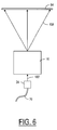
- the fourth display mode of the portable device 1 is illustrated in Figure 6 .
- the imaging optics 36 are rearranged or reconfigured to project the real image by an image-forming beam 108 to a larger screen 64 at a larger distance.
- an external light source is used to provide an intense light beam to illuminate the microdisplay 32 , 32 '.
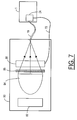
- a light guide 70 to convey an illuminating light beam from an external light source 80 ( Figure 7 ) to the portable device 1 through the connector 24 . It is possible to use additional lenses and other optical components disposed between the optical engine 16 and the screen 64 to reconfigure the NED optics.
- the light source for projection is typically a discharge lamp, such as an Ultra High Pressure (UHP) Mercury lamp.
- UHP Ultra High Pressure
- the efficiency of such a lamp is typically only about 10%, and the rest of the power is converted to heat.
- IR Infra Red
- This problem is compounded by the fact that there would not be sufficient space in the portable device to include an effective cooling system to dissipate the heat associated with the light source.
- an external light source 80 such as the one shown in Figure 7 , must be used, instead of the internal light source 20 .
- a lamp 84 with a reflector is used as a light source.
- the lamp 84 is powered by a power supply 82 .
- the light output from the lamp is filtered by an IR/UV filter 86 and focused into the light guide 70 .
- a light sequencer 88 is provided in the light path to turn the light beam to the light guide 70 into sequential colors under the control of the portable device 1 .
- an electrical cable 72 connecting the portable device 1 to the external light source 80 allows the portable device 1 to send a control signal to the light sequencer 88 according to the selected display mode.
- the portable device includes an optical engine, which is adapted to form an image according to one or more display modes.
- the portable device is designed such that the change between different display modes can be easily carried out.
Landscapes
- Physics & Mathematics (AREA)
- General Physics & Mathematics (AREA)
- Engineering & Computer Science (AREA)
- Optics & Photonics (AREA)
- Multimedia (AREA)
- Signal Processing (AREA)
- Theoretical Computer Science (AREA)
- General Engineering & Computer Science (AREA)
- Devices For Indicating Variable Information By Combining Individual Elements (AREA)
- Details Of Measuring Devices (AREA)
- Projection Apparatus (AREA)
- Liquid Crystal (AREA)
Claims (17)
- Dispositif portatif (1) capable de fournir une pluralité de modes d'affichage sélectionnables afin de fournir une image à un visionneur (150), les modes d'affichage sélectionnables comprenant :un premier mode permettant au visionneur (150) de percevoir l'image en plaçant un oeil du visionneur dans la trajectoire optique (130) ; etun deuxième mode permettant au visionneur de percevoir l'image formée sur une surface disposée dans la trajectoire optique, et ledit dispositif portatif comprenant :une source d'image (32 ; 32' ; 32") ;une unité électronique (14) fournissant des données d'image à la source d'image ;une source de lumière (20) fournissant une lumière d'éclairage à la source d'image pour fournir une lumière de sortie (104) depuis la source d'image ;un agencement optique (36) de composants optiques formant l'image à partir de la lumière de sortie produite par la source d'image le long d'une trajectoire optique (130) de l'agencement, dans lequel l'agencement optique des composants optiques est adapté pour changer de telle sorte que ladite formation d'image soit basée sur un mode sélectionné des modes d'affichage, dans lequel le premier mode est utilisé pour former une image virtuelle et dans lequel le deuxième mode est un mode de projection d'image réelle.
- Dispositif portatif selon la revendication 1, dans lequel les modes d'affichage sélectionnés comportent :un premier mode permettant au visionneur (150) de percevoir l'image en plaçant un oeil du visionneur dans la trajectoire optique (130) à proximité du dispositif portatif ; etun deuxième mode pour permettre au visionneur de percevoir l'image formée sur une surface disposée dans la trajectoire optique à proximité du dispositif portatif.
- Dispositif portatif selon la revendication 1, dans lequel les modes d'affichage sélectionnés comportent :un premier mode permettant au visionneur (150) de percevoir l'image en plaçant un oeil du visionneur dans la trajectoire optique (130) à proximité du dispositif portatif ; etun deuxième mode pour permettre au visionneur de percevoir l'image formée sur une surface disposée dans la trajectoire optique à une distance du dispositif portatif.
- Dispositif portatif selon la revendication 1, dans lequel les modes d'affichage sélectionnés comportent :un premier mode permettant au visionneur (150) de percevoir l'image en plaçant un oeil du visionneur dans la trajectoire optique (130) à une distance du dispositif portatif ; etun deuxième mode pour permettre au visionneur de percevoir l'image formée sur une surface disposée dans la trajectoire optique à proximité du dispositif portatif.
- Dispositif portatif selon la revendication 1, dans lequel les modes d'affichage sélectionnés comportent :un premier mode permettant au visionneur (150) de percevoir l'image en plaçant un oeil du visionneur dans la trajectoire optique (130) à une distance du dispositif portatif ; etun deuxième mode pour permettre au visionneur de percevoir l'image formée sur une surface disposée dans la trajectoire optique à une distance du dispositif portatif.
- Dispositif portatif selon la revendication 2, dans lequel les modes d'affichage sélectionnables comportent en outre un troisième mode permettant au visionneur (150) de percevoir l'image en plaçant l'oeil dans la trajectoire optique (130) à une distance du dispositif portatif.
- Dispositif portatif selon la revendication 2, dans lequel les modes d'affichage sélectionnables comportent en outre un troisième mode permettant au visionneur (150) de percevoir l'image formée sur une autre surface disposée dans la trajectoire optique (130) à une distance du dispositif portatif.
- Dispositif portatif selon la revendication 7, dans lequel les modes d'affichage sélectionnables comportent en outre un quatrième mode permettant au visionneur (150) de percevoir l'image en plaçant l'oeil dans la trajectoire optique (130) à une distance du dispositif portatif.
- Dispositif portatif selon l'une quelconque des revendications précédentes, dans lequel la source d'image (32 ; 32' ; 32") est un dispositif de micro-affichage du type réflectif (32).
- Dispositif portatif selon l'une quelconque des revendications 1 à 8, dans lequel la source d'image (32 ; 32' ; 32") est un dispositif de micro-affichage du type transmissif (32').
- Dispositif portatif selon l'une quelconque des revendications 1 à 8, dans lequel la source d'image (32 ; 32' ; 32") est un dispositif de micro-affichage du type émissif (32").
- Dispositif portatif selon l'une quelconque des revendications précédentes, dans lequel la source de lumière comprend :un premier dispositif d'éclairage alimenté par une ou plusieurs batteries disposées à l'intérieur du dispositif portatif, etun connecteur (24) connectant une extrémité d'un guide de lumière (70) au dispositif portatif, le guide de lumière acheminant jusqu'au dispositif portatif un faisceau de lumière produit par une source de lumière externe (84) ; et dans lequel le premier dispositif d'éclairage est utilisé pour fournir la lumière d'éclairage à la source d'image quand le mode sélectionné des modes d'affichage est le premier mode, etla source de lumière externe est utilisée pour fournir la lumière d'éclairage à la source d'image quand le mode sélectionné des modes d'affichage est le deuxième mode.
- Dispositif portatif selon la revendication 12 dépendant de la revendication 7, dans lequel la source de lumière externe est utilisée pour fournir la lumière d'éclairage à la source d'image quand le mode sélectionné des modes d'affichage est le troisième mode.
- Dispositif portatif selon la revendication 12 dépendant de la revendication 8, dans lequel le premier dispositif d'éclairage est utilisé pour fournir la lumière d'éclairage à la source d'image quand le mode sélectionné des modes d'affichage est le premier mode ou le quatrième mode, et
la source de lumière externe est utilisée pour fournir la lumière d'éclairage à la source d'image quand le mode sélectionné des modes d'affichage est le troisième mode. - Dispositif portatif selon la revendication 1, comprenant en outre un dispositif de polarisation, disposé adjacent à la source d'image, pour sélectionner un premier état de polarisation dans la lumière d'éclairage allant à la source d'image et un deuxième état de polarisation dans la lumière de sortie de la source d'image, dans lequel le premier état de polarisation est différent du deuxième état de polarisation.
- Dispositif portatif selon la revendication 9, comprenant en outre un diviseur de faisceau de polarisation, disposé adjacent à la source d'image, pour sélectionner un premier état de polarisation dans la lumière d'éclairage allant à la source d'image et un deuxième état de polarisation dans la lumière de sortie de la source d'image, dans lequel le premier état de polarisation est différent du deuxième état de polarisation.
- Système comprenant le dispositif portatif selon l'une quelconque des revendications précédentes et une source de lumière externe, dans lequel la source de lumière externe comprend un dispositif de commande capable de fonctionner
dans un premier mode opérationnel empêchant le faisceau de lumière fourni par la source de lumière externe d'être acheminé par le guide de lumière jusqu'au dispositif portatif, et
dans un deuxième mode opérationnel permettant au faisceau de lumière provenant de la source de lumière externe d'être acheminé par le guide de lumière jusqu'au dispositif portatif, et dans lequel le dispositif portatif comprend en outre un moyen, sensible aux modes d'affichage, pour envoyer un signal au dispositif de commande pour sélectionner le premier mode opérationnel quand le mode sélectionné des modes d'affichage est le premier mode, et pour sélectionner le deuxième mode opérationnel quand le mode sélectionné des modes d'affichage est le deuxième mode.
Applications Claiming Priority (3)
| Application Number | Priority Date | Filing Date | Title |
|---|---|---|---|
| US10932 | 1993-01-29 | ||
| US10/010,932 US6773114B2 (en) | 2001-12-07 | 2001-12-07 | Portable multimode display device |
| PCT/IB2002/005118 WO2003049146A2 (fr) | 2001-12-07 | 2002-12-04 | Dispositif d'affichage portatif a modes multiples |
Publications (3)
| Publication Number | Publication Date |
|---|---|
| EP1451639A2 EP1451639A2 (fr) | 2004-09-01 |
| EP1451639A4 EP1451639A4 (fr) | 2006-03-01 |
| EP1451639B1 true EP1451639B1 (fr) | 2016-11-02 |
Family
ID=21748086
Family Applications (1)
| Application Number | Title | Priority Date | Filing Date |
|---|---|---|---|
| EP02785816.6A Expired - Lifetime EP1451639B1 (fr) | 2001-12-07 | 2002-12-04 | Dispositif d'affichage portatif a modes multiples |
Country Status (8)
| Country | Link |
|---|---|
| US (1) | US6773114B2 (fr) |
| EP (1) | EP1451639B1 (fr) |
| JP (2) | JP2005512135A (fr) |
| KR (1) | KR100960056B1 (fr) |
| CN (1) | CN100412683C (fr) |
| AU (1) | AU2002351103A1 (fr) |
| IL (2) | IL161805A0 (fr) |
| WO (1) | WO2003049146A2 (fr) |
Families Citing this family (66)
| Publication number | Priority date | Publication date | Assignee | Title |
|---|---|---|---|---|
| ATE536050T1 (de) * | 2004-04-29 | 2011-12-15 | Koninkl Philips Electronics Nv | In der hand gehaltene projektionseinrichtung |
| JP2006091112A (ja) * | 2004-09-21 | 2006-04-06 | Nikon Corp | 電子機器 |
| US7413328B2 (en) * | 2004-12-30 | 2008-08-19 | Honeywell International Inc. | Remotely coupled hybrid HUD backlight |
| US20060145947A1 (en) * | 2005-01-04 | 2006-07-06 | Arneson Theodore R | Foldable electronic device with virtual image display |
| US20060146013A1 (en) * | 2005-01-04 | 2006-07-06 | Arneson Theodore R | Electronic device with virtual image display |
| US7539513B2 (en) | 2005-02-02 | 2009-05-26 | National Telephone Products, Inc. | Portable phone with ergonomic image projection system |
| TWI276906B (en) * | 2005-04-22 | 2007-03-21 | Liu-Jen Chen | Portable information product with projection equipment |
| GB0522968D0 (en) | 2005-11-11 | 2005-12-21 | Popovich Milan M | Holographic illumination device |
| US7862185B2 (en) * | 2006-03-30 | 2011-01-04 | Citizen Electronics Co., Ltd. | Mobile phone |
| GB0718706D0 (en) | 2007-09-25 | 2007-11-07 | Creative Physics Ltd | Method and apparatus for reducing laser speckle |
| TWM315847U (en) * | 2006-11-29 | 2007-07-21 | Hau-Wen Chen | Portable information product with DLP projection apparatus |
| WO2008071830A1 (fr) * | 2006-12-14 | 2008-06-19 | Nokia Corporation | Dispositif d'affichage ayant deux modes de fonctionnement |
| EP2127367B1 (fr) * | 2007-02-20 | 2017-03-29 | Daegu Gyeongbuk Institute Of Science&Technology | Lecteur multimédia affichant deux images de projection |
| US20100039518A1 (en) * | 2007-10-10 | 2010-02-18 | Hao-Wen Chen | Portable information product with laser projection |
| US11726332B2 (en) | 2009-04-27 | 2023-08-15 | Digilens Inc. | Diffractive projection apparatus |
| US9335604B2 (en) | 2013-12-11 | 2016-05-10 | Milan Momcilo Popovich | Holographic waveguide display |
| US11204540B2 (en) | 2009-10-09 | 2021-12-21 | Digilens Inc. | Diffractive waveguide providing a retinal image |
| US20120108298A1 (en) * | 2010-10-29 | 2012-05-03 | Symbol Technologies, Inc. | Portable device having a virtual display |
| KR20120067766A (ko) | 2010-12-16 | 2012-06-26 | 삼성전자주식회사 | 프로 젝터가 내장된 카메라 장치의 이중 디스플레이 장치 |
| US9274349B2 (en) | 2011-04-07 | 2016-03-01 | Digilens Inc. | Laser despeckler based on angular diversity |
| WO2016020630A2 (fr) | 2014-08-08 | 2016-02-11 | Milan Momcilo Popovich | Illuminateur laser en guide d'ondes comprenant un dispositif de déchatoiement |
| US10670876B2 (en) | 2011-08-24 | 2020-06-02 | Digilens Inc. | Waveguide laser illuminator incorporating a despeckler |
| EP2748670B1 (fr) | 2011-08-24 | 2015-11-18 | Rockwell Collins, Inc. | Affichage de données portable |
| US20150010265A1 (en) | 2012-01-06 | 2015-01-08 | Milan, Momcilo POPOVICH | Contact image sensor using switchable bragg gratings |
| CN103309039B (zh) * | 2012-03-12 | 2016-12-14 | 联想(北京)有限公司 | 手持电子设备和显示方法 |
| US9230515B2 (en) | 2012-03-12 | 2016-01-05 | Lenovo (Beijing) Co., Ltd. | Hand-held electronic device and display method |
| EP2842003B1 (fr) | 2012-04-25 | 2019-02-27 | Rockwell Collins, Inc. | Affichage grand angle holographique |
| US9456744B2 (en) | 2012-05-11 | 2016-10-04 | Digilens, Inc. | Apparatus for eye tracking |
| CN110083202B (zh) * | 2012-07-27 | 2023-09-19 | 诺基亚技术有限公司 | 与近眼显示器的多模交互 |
| US9933684B2 (en) | 2012-11-16 | 2018-04-03 | Rockwell Collins, Inc. | Transparent waveguide display providing upper and lower fields of view having a specific light output aperture configuration |
| US10209517B2 (en) | 2013-05-20 | 2019-02-19 | Digilens, Inc. | Holographic waveguide eye tracker |
| US9727772B2 (en) | 2013-07-31 | 2017-08-08 | Digilens, Inc. | Method and apparatus for contact image sensing |
| WO2016020632A1 (fr) | 2014-08-08 | 2016-02-11 | Milan Momcilo Popovich | Procédé pour gravure par pressage et réplication holographique |
| WO2016042283A1 (fr) | 2014-09-19 | 2016-03-24 | Milan Momcilo Popovich | Procédé et appareil de production d'images d'entrée pour affichages à guides d'ondes holographiques |
| EP3198192A1 (fr) | 2014-09-26 | 2017-08-02 | Milan Momcilo Popovich | Dispositif de poursuite optique à guide d'ondes holographique |
| CN105572868B (zh) * | 2014-10-13 | 2018-01-23 | 联想(北京)有限公司 | 显示设备和显示方法 |
| US10437064B2 (en) | 2015-01-12 | 2019-10-08 | Digilens Inc. | Environmentally isolated waveguide display |
| EP3245551B1 (fr) | 2015-01-12 | 2019-09-18 | DigiLens Inc. | Afficheurs à champ lumineux et à guide d'ondes |
| CN107533137A (zh) | 2015-01-20 | 2018-01-02 | 迪吉伦斯公司 | 全息波导激光雷达 |
| US9632226B2 (en) | 2015-02-12 | 2017-04-25 | Digilens Inc. | Waveguide grating device |
| WO2016146963A1 (fr) | 2015-03-16 | 2016-09-22 | Popovich, Milan, Momcilo | Dispositif de guide d'onde incorporant un conduit de lumière |
| US10591756B2 (en) | 2015-03-31 | 2020-03-17 | Digilens Inc. | Method and apparatus for contact image sensing |
| WO2017060665A1 (fr) | 2015-10-05 | 2017-04-13 | Milan Momcilo Popovich | Afficheur à guide d'ondes |
| EP3398007B1 (fr) | 2016-02-04 | 2024-09-11 | DigiLens, Inc. | Dispositif de poursuite optique de guide d'onde |
| JP6895451B2 (ja) | 2016-03-24 | 2021-06-30 | ディジレンズ インコーポレイテッド | 偏光選択ホログラフィー導波管デバイスを提供するための方法および装置 |
| EP3433658B1 (fr) | 2016-04-11 | 2023-08-09 | DigiLens, Inc. | Dispositif guide d'onde pour la projection de lumiere structuree |
| EP3548939A4 (fr) | 2016-12-02 | 2020-11-25 | DigiLens Inc. | Dispositif de guide d'ondes à éclairage de sortie uniforme |
| US10545346B2 (en) | 2017-01-05 | 2020-01-28 | Digilens Inc. | Wearable heads up displays |
| CN111386495B (zh) | 2017-10-16 | 2022-12-09 | 迪吉伦斯公司 | 用于倍增像素化显示器的图像分辨率的系统和方法 |
| JP7404243B2 (ja) | 2018-01-08 | 2023-12-25 | ディジレンズ インコーポレイテッド | 導波管セル内のホログラフィック格子の高スループット記録のためのシステムおよび方法 |
| WO2019136476A1 (fr) | 2018-01-08 | 2019-07-11 | Digilens, Inc. | Architectures de guides d'ondes et procédés de fabrication associés |
| CN114721242B (zh) | 2018-01-08 | 2025-08-15 | 迪吉伦斯公司 | 用于制造光学波导的方法 |
| JP7456929B2 (ja) | 2018-01-08 | 2024-03-27 | ディジレンズ インコーポレイテッド | 導波管セルを製造するためのシステムおよび方法 |
| US10690851B2 (en) | 2018-03-16 | 2020-06-23 | Digilens Inc. | Holographic waveguides incorporating birefringence control and methods for their fabrication |
| US11402801B2 (en) | 2018-07-25 | 2022-08-02 | Digilens Inc. | Systems and methods for fabricating a multilayer optical structure |
| WO2020149956A1 (fr) | 2019-01-14 | 2020-07-23 | Digilens Inc. | Affichage de guide d'ondes holographique avec couche de commande de lumière |
| US20200247017A1 (en) | 2019-02-05 | 2020-08-06 | Digilens Inc. | Methods for Compensating for Optical Surface Nonuniformity |
| US20220283377A1 (en) | 2019-02-15 | 2022-09-08 | Digilens Inc. | Wide Angle Waveguide Display |
| EP3924759B1 (fr) | 2019-02-15 | 2025-07-30 | Digilens Inc. | Procédés et appareils pour fournir un affichage de guide d'ondes holographique à l'aide de réseaux intégrés |
| JP2022525165A (ja) | 2019-03-12 | 2022-05-11 | ディジレンズ インコーポレイテッド | ホログラフィック導波管バックライトおよび関連する製造方法 |
| EP3980825A4 (fr) | 2019-06-07 | 2023-05-03 | Digilens Inc. | Guides d'ondes incorporant des réseaux transparents et réfléchissants et procédés de fabrication associés |
| JP2022543571A (ja) | 2019-07-29 | 2022-10-13 | ディジレンズ インコーポレイテッド | 画素化されたディスプレイの画像解像度および視野を乗算するための方法および装置 |
| JP2022546413A (ja) | 2019-08-29 | 2022-11-04 | ディジレンズ インコーポレイテッド | 真空回折格子および製造方法 |
| EP4252048A4 (fr) | 2020-12-21 | 2024-10-16 | Digilens Inc. | Suppression de la luminescence de l'oeil dans des affichages à base de guide d'ondes |
| WO2022150841A1 (fr) | 2021-01-07 | 2022-07-14 | Digilens Inc. | Structures de réseau pour guides d'ondes de couleur |
| KR20230153459A (ko) | 2021-03-05 | 2023-11-06 | 디지렌즈 인코포레이티드. | 진공 주기적 구조체 및 제조 방법 |
Citations (2)
| Publication number | Priority date | Publication date | Assignee | Title |
|---|---|---|---|---|
| EP0770896A1 (fr) * | 1995-10-23 | 1997-05-02 | Motorola, Inc. | Dispositif d'affichage d'image double avec un boîtier électro-optique intégré |
| US20010027125A1 (en) * | 2000-03-22 | 2001-10-04 | Satoshi Kiyomatsu | Virtual image display apparatus and electronic equipment using thereof |
Family Cites Families (19)
| Publication number | Priority date | Publication date | Assignee | Title |
|---|---|---|---|---|
| US2170967A (en) * | 1937-07-21 | 1939-08-29 | Zeiss Carl Fa | Projecting apparatus |
| DE3720375A1 (de) * | 1987-06-19 | 1988-12-29 | Fraunhofer Ges Forschung | Projektionsvorrichtung |
| JPH0378374A (ja) * | 1989-08-22 | 1991-04-03 | Hitachi Ltd | 映像再生方式 |
| JPH0461975U (fr) * | 1990-10-08 | 1992-05-27 | ||
| JPH04307875A (ja) * | 1991-04-05 | 1992-10-30 | Fuji Photo Film Co Ltd | 液晶ファインダ付きビデオカメラ |
| JPH0518171U (ja) * | 1991-06-12 | 1993-03-05 | 日本ビクター株式会社 | 撮像機能付き記録再生装置 |
| CN1071291A (zh) * | 1991-09-30 | 1993-04-21 | 莫托罗拉公司 | 带有小型虚像显示器的便携式通讯接收机 |
| JPH05344392A (ja) * | 1992-06-12 | 1993-12-24 | Fuji Photo Optical Co Ltd | 電子ビューファインダ |
| JP3277469B2 (ja) * | 1992-08-07 | 2002-04-22 | ソニー株式会社 | ビデオカメラ及び映像表示装置 |
| JPH06303467A (ja) * | 1993-04-13 | 1994-10-28 | Omron Corp | 画像表示装置及び撮影装置 |
| JPH07113997A (ja) * | 1993-10-14 | 1995-05-02 | Gold Star Co Ltd | 液晶プロジェクター内蔵vtr |
| US5485318A (en) * | 1994-10-03 | 1996-01-16 | Motorola, Inc. | Dual image manifestation apparatus with integrated electro-optical package |
| US5539554A (en) * | 1994-12-21 | 1996-07-23 | Motorola | Integrated electro-optic package for reflective spatial light |
| TW324818B (en) * | 1995-09-18 | 1998-01-11 | Motorola Inc | Multi-mode image manifestation apparatus |
| TW393582B (en) * | 1995-12-05 | 2000-06-11 | Matsushita Electric Industrial Co Ltd | Backlighting device and color display device |
| JP3987187B2 (ja) * | 1998-02-17 | 2007-10-03 | 株式会社リコー | 画像表示装置 |
| KR19990085242A (ko) * | 1998-05-15 | 1999-12-06 | 구자홍 | 노트북 컴퓨터 겸용 프로젝터 |
| JP2001201713A (ja) * | 2000-01-21 | 2001-07-27 | Toshiba Corp | 映像表示装置 |
| JP2001313702A (ja) * | 2000-04-28 | 2001-11-09 | Cadix Inc | 携帯通信端末 |
-
2001
- 2001-12-07 US US10/010,932 patent/US6773114B2/en not_active Expired - Lifetime
-
2002
- 2002-12-04 IL IL16180502A patent/IL161805A0/xx unknown
- 2002-12-04 KR KR1020047008293A patent/KR100960056B1/ko not_active Expired - Fee Related
- 2002-12-04 JP JP2003550251A patent/JP2005512135A/ja active Pending
- 2002-12-04 WO PCT/IB2002/005118 patent/WO2003049146A2/fr not_active Ceased
- 2002-12-04 AU AU2002351103A patent/AU2002351103A1/en not_active Abandoned
- 2002-12-04 EP EP02785816.6A patent/EP1451639B1/fr not_active Expired - Lifetime
- 2002-12-04 CN CNB028244893A patent/CN100412683C/zh not_active Expired - Fee Related
-
2004
- 2004-05-06 IL IL161805A patent/IL161805A/en not_active IP Right Cessation
-
2009
- 2009-06-01 JP JP2009132570A patent/JP2009211091A/ja active Pending
Patent Citations (2)
| Publication number | Priority date | Publication date | Assignee | Title |
|---|---|---|---|---|
| EP0770896A1 (fr) * | 1995-10-23 | 1997-05-02 | Motorola, Inc. | Dispositif d'affichage d'image double avec un boîtier électro-optique intégré |
| US20010027125A1 (en) * | 2000-03-22 | 2001-10-04 | Satoshi Kiyomatsu | Virtual image display apparatus and electronic equipment using thereof |
Also Published As
| Publication number | Publication date |
|---|---|
| US20030107883A1 (en) | 2003-06-12 |
| CN100412683C (zh) | 2008-08-20 |
| KR100960056B1 (ko) | 2010-05-31 |
| KR20050058255A (ko) | 2005-06-16 |
| IL161805A0 (en) | 2005-11-20 |
| WO2003049146A2 (fr) | 2003-06-12 |
| AU2002351103A8 (en) | 2003-06-17 |
| IL161805A (en) | 2010-12-30 |
| WO2003049146A3 (fr) | 2004-01-22 |
| AU2002351103A1 (en) | 2003-06-17 |
| JP2005512135A (ja) | 2005-04-28 |
| EP1451639A2 (fr) | 2004-09-01 |
| JP2009211091A (ja) | 2009-09-17 |
| CN1602447A (zh) | 2005-03-30 |
| EP1451639A4 (fr) | 2006-03-01 |
| US6773114B2 (en) | 2004-08-10 |
Similar Documents
| Publication | Publication Date | Title |
|---|---|---|
| EP1451639B1 (fr) | Dispositif d'affichage portatif a modes multiples | |
| US6474819B2 (en) | Combination overhead projector and electronic display device | |
| US7901084B2 (en) | Image projector with display modes | |
| US6452577B1 (en) | Microdisplay viewer | |
| TW399194B (en) | Portable communication display system | |
| EP0566000B1 (fr) | Système d'affichage d'image virtuelle | |
| US6559825B2 (en) | Display system for wireless pager | |
| TW548966B (en) | Image capturing camera and projector device | |
| US20020113912A1 (en) | Dual model near-eye and projection display system | |
| CN101082763A (zh) | 便携式电子设备 | |
| JPH10178606A (ja) | 通信端末および可視認識情報の投影装置 | |
| JP2010224015A (ja) | 投写型映像表示装置及び記載ボード及び投写映像システム | |
| US6650305B1 (en) | Wireless electronic display | |
| US6883918B2 (en) | Portable, digital projector device and a system using the same | |
| JPH10333247A (ja) | 投写型表示装置 | |
| US20020145573A1 (en) | Compact portable virtual image display | |
| US20110019057A1 (en) | Electronic Playback Apparatus with a Micro-Projector | |
| US7693316B2 (en) | Apparatus and method for displaying hologram of a mobile communication terminal | |
| JP2008165077A (ja) | 画像投影装置 | |
| JP3048667B2 (ja) | 視線一致表示装置 | |
| JPH10268228A (ja) | 頭部装着型表示装置 | |
| JP3096329B2 (ja) | 携帯用表示装置 | |
| JP2006146086A (ja) | 携帯情報端末 | |
| JP2018147210A (ja) | 表示システム、表示装置、端末装置、表示システムの制御方法、表示装置の制御プログラムおよび端末装置の制御プログラム |
Legal Events
| Date | Code | Title | Description |
|---|---|---|---|
| PUAI | Public reference made under article 153(3) epc to a published international application that has entered the european phase |
Free format text: ORIGINAL CODE: 0009012 |
|
| 17P | Request for examination filed |
Effective date: 20040511 |
|
| AK | Designated contracting states |
Kind code of ref document: A2 Designated state(s): AT BE BG CH CY CZ DE DK EE ES FI FR GB GR IE IT LI LU MC NL PT SE SI SK TR |
|
| AX | Request for extension of the european patent |
Extension state: AL LT LV MK RO |
|
| A4 | Supplementary search report drawn up and despatched |
Effective date: 20060116 |
|
| 17Q | First examination report despatched |
Effective date: 20060620 |
|
| RAP1 | Party data changed (applicant data changed or rights of an application transferred) |
Owner name: NOKIA CORPORATION |
|
| RAP1 | Party data changed (applicant data changed or rights of an application transferred) |
Owner name: NOKIA TECHNOLOGIES OY |
|
| REG | Reference to a national code |
Ref country code: DE Ref legal event code: R079 Ref document number: 60248458 Country of ref document: DE Free format text: PREVIOUS MAIN CLASS: G03B0021140000 Ipc: G02B0027010000 |
|
| GRAP | Despatch of communication of intention to grant a patent |
Free format text: ORIGINAL CODE: EPIDOSNIGR1 |
|
| RIC1 | Information provided on ipc code assigned before grant |
Ipc: H04N 9/31 20060101ALI20160503BHEP Ipc: G02B 27/01 20060101AFI20160503BHEP Ipc: H04N 5/74 20060101ALI20160503BHEP |
|
| INTG | Intention to grant announced |
Effective date: 20160523 |
|
| GRAS | Grant fee paid |
Free format text: ORIGINAL CODE: EPIDOSNIGR3 |
|
| GRAA | (expected) grant |
Free format text: ORIGINAL CODE: 0009210 |
|
| AK | Designated contracting states |
Kind code of ref document: B1 Designated state(s): AT BE BG CH CY CZ DE DK EE ES FI FR GB GR IE IT LI LU MC NL PT SE SI SK TR |
|
| REG | Reference to a national code |
Ref country code: GB Ref legal event code: FG4D |
|
| REG | Reference to a national code |
Ref country code: AT Ref legal event code: REF Ref document number: 842408 Country of ref document: AT Kind code of ref document: T Effective date: 20161115 Ref country code: CH Ref legal event code: EP |
|
| REG | Reference to a national code |
Ref country code: IE Ref legal event code: FG4D |
|
| REG | Reference to a national code |
Ref country code: DE Ref legal event code: R096 Ref document number: 60248458 Country of ref document: DE |
|
| REG | Reference to a national code |
Ref country code: NL Ref legal event code: FP |
|
| REG | Reference to a national code |
Ref country code: AT Ref legal event code: MK05 Ref document number: 842408 Country of ref document: AT Kind code of ref document: T Effective date: 20161102 |
|
| PG25 | Lapsed in a contracting state [announced via postgrant information from national office to epo] |
Ref country code: GR Free format text: LAPSE BECAUSE OF FAILURE TO SUBMIT A TRANSLATION OF THE DESCRIPTION OR TO PAY THE FEE WITHIN THE PRESCRIBED TIME-LIMIT Effective date: 20170203 Ref country code: SE Free format text: LAPSE BECAUSE OF FAILURE TO SUBMIT A TRANSLATION OF THE DESCRIPTION OR TO PAY THE FEE WITHIN THE PRESCRIBED TIME-LIMIT Effective date: 20161102 |
|
| PG25 | Lapsed in a contracting state [announced via postgrant information from national office to epo] |
Ref country code: ES Free format text: LAPSE BECAUSE OF FAILURE TO SUBMIT A TRANSLATION OF THE DESCRIPTION OR TO PAY THE FEE WITHIN THE PRESCRIBED TIME-LIMIT Effective date: 20161102 Ref country code: FI Free format text: LAPSE BECAUSE OF FAILURE TO SUBMIT A TRANSLATION OF THE DESCRIPTION OR TO PAY THE FEE WITHIN THE PRESCRIBED TIME-LIMIT Effective date: 20161102 Ref country code: PT Free format text: LAPSE BECAUSE OF FAILURE TO SUBMIT A TRANSLATION OF THE DESCRIPTION OR TO PAY THE FEE WITHIN THE PRESCRIBED TIME-LIMIT Effective date: 20170302 Ref country code: BE Free format text: LAPSE BECAUSE OF NON-PAYMENT OF DUE FEES Effective date: 20161231 Ref country code: AT Free format text: LAPSE BECAUSE OF FAILURE TO SUBMIT A TRANSLATION OF THE DESCRIPTION OR TO PAY THE FEE WITHIN THE PRESCRIBED TIME-LIMIT Effective date: 20161102 |
|
| PG25 | Lapsed in a contracting state [announced via postgrant information from national office to epo] |
Ref country code: CZ Free format text: LAPSE BECAUSE OF FAILURE TO SUBMIT A TRANSLATION OF THE DESCRIPTION OR TO PAY THE FEE WITHIN THE PRESCRIBED TIME-LIMIT Effective date: 20161102 Ref country code: SK Free format text: LAPSE BECAUSE OF FAILURE TO SUBMIT A TRANSLATION OF THE DESCRIPTION OR TO PAY THE FEE WITHIN THE PRESCRIBED TIME-LIMIT Effective date: 20161102 Ref country code: DK Free format text: LAPSE BECAUSE OF FAILURE TO SUBMIT A TRANSLATION OF THE DESCRIPTION OR TO PAY THE FEE WITHIN THE PRESCRIBED TIME-LIMIT Effective date: 20161102 Ref country code: EE Free format text: LAPSE BECAUSE OF FAILURE TO SUBMIT A TRANSLATION OF THE DESCRIPTION OR TO PAY THE FEE WITHIN THE PRESCRIBED TIME-LIMIT Effective date: 20161102 |
|
| REG | Reference to a national code |
Ref country code: CH Ref legal event code: PL |
|
| REG | Reference to a national code |
Ref country code: DE Ref legal event code: R097 Ref document number: 60248458 Country of ref document: DE |
|
| PG25 | Lapsed in a contracting state [announced via postgrant information from national office to epo] |
Ref country code: BG Free format text: LAPSE BECAUSE OF FAILURE TO SUBMIT A TRANSLATION OF THE DESCRIPTION OR TO PAY THE FEE WITHIN THE PRESCRIBED TIME-LIMIT Effective date: 20170202 Ref country code: IT Free format text: LAPSE BECAUSE OF FAILURE TO SUBMIT A TRANSLATION OF THE DESCRIPTION OR TO PAY THE FEE WITHIN THE PRESCRIBED TIME-LIMIT Effective date: 20161102 Ref country code: BE Free format text: LAPSE BECAUSE OF FAILURE TO SUBMIT A TRANSLATION OF THE DESCRIPTION OR TO PAY THE FEE WITHIN THE PRESCRIBED TIME-LIMIT Effective date: 20161102 |
|
| PLBE | No opposition filed within time limit |
Free format text: ORIGINAL CODE: 0009261 |
|
| STAA | Information on the status of an ep patent application or granted ep patent |
Free format text: STATUS: NO OPPOSITION FILED WITHIN TIME LIMIT |
|
| PG25 | Lapsed in a contracting state [announced via postgrant information from national office to epo] |
Ref country code: MC Free format text: LAPSE BECAUSE OF FAILURE TO SUBMIT A TRANSLATION OF THE DESCRIPTION OR TO PAY THE FEE WITHIN THE PRESCRIBED TIME-LIMIT Effective date: 20161102 |
|
| REG | Reference to a national code |
Ref country code: FR Ref legal event code: ST Effective date: 20170831 |
|
| REG | Reference to a national code |
Ref country code: IE Ref legal event code: MM4A |
|
| 26N | No opposition filed |
Effective date: 20170803 |
|
| GBPC | Gb: european patent ceased through non-payment of renewal fee |
Effective date: 20170202 |
|
| PG25 | Lapsed in a contracting state [announced via postgrant information from national office to epo] |
Ref country code: CH Free format text: LAPSE BECAUSE OF NON-PAYMENT OF DUE FEES Effective date: 20161231 Ref country code: FR Free format text: LAPSE BECAUSE OF NON-PAYMENT OF DUE FEES Effective date: 20170102 Ref country code: LI Free format text: LAPSE BECAUSE OF NON-PAYMENT OF DUE FEES Effective date: 20161231 Ref country code: LU Free format text: LAPSE BECAUSE OF NON-PAYMENT OF DUE FEES Effective date: 20161204 |
|
| PG25 | Lapsed in a contracting state [announced via postgrant information from national office to epo] |
Ref country code: SI Free format text: LAPSE BECAUSE OF FAILURE TO SUBMIT A TRANSLATION OF THE DESCRIPTION OR TO PAY THE FEE WITHIN THE PRESCRIBED TIME-LIMIT Effective date: 20161102 Ref country code: IE Free format text: LAPSE BECAUSE OF NON-PAYMENT OF DUE FEES Effective date: 20161204 |
|
| PG25 | Lapsed in a contracting state [announced via postgrant information from national office to epo] |
Ref country code: GB Free format text: LAPSE BECAUSE OF NON-PAYMENT OF DUE FEES Effective date: 20170202 |
|
| PG25 | Lapsed in a contracting state [announced via postgrant information from national office to epo] |
Ref country code: CY Free format text: LAPSE BECAUSE OF FAILURE TO SUBMIT A TRANSLATION OF THE DESCRIPTION OR TO PAY THE FEE WITHIN THE PRESCRIBED TIME-LIMIT Effective date: 20161102 |
|
| PG25 | Lapsed in a contracting state [announced via postgrant information from national office to epo] |
Ref country code: TR Free format text: LAPSE BECAUSE OF FAILURE TO SUBMIT A TRANSLATION OF THE DESCRIPTION OR TO PAY THE FEE WITHIN THE PRESCRIBED TIME-LIMIT Effective date: 20161102 |
|
| PGFP | Annual fee paid to national office [announced via postgrant information from national office to epo] |
Ref country code: NL Payment date: 20201113 Year of fee payment: 19 |
|
| PGFP | Annual fee paid to national office [announced via postgrant information from national office to epo] |
Ref country code: DE Payment date: 20201124 Year of fee payment: 19 |
|
| REG | Reference to a national code |
Ref country code: DE Ref legal event code: R119 Ref document number: 60248458 Country of ref document: DE |
|
| REG | Reference to a national code |
Ref country code: NL Ref legal event code: MM Effective date: 20220101 |
|
| PG25 | Lapsed in a contracting state [announced via postgrant information from national office to epo] |
Ref country code: NL Free format text: LAPSE BECAUSE OF NON-PAYMENT OF DUE FEES Effective date: 20220101 |
|
| PG25 | Lapsed in a contracting state [announced via postgrant information from national office to epo] |
Ref country code: DE Free format text: LAPSE BECAUSE OF NON-PAYMENT OF DUE FEES Effective date: 20220701 |