EP1452111B1 - Vorrichtung zum Speichern und Applizieren eines kosmetischen Produktes - Google Patents
Vorrichtung zum Speichern und Applizieren eines kosmetischen Produktes Download PDFInfo
- Publication number
- EP1452111B1 EP1452111B1 EP04290459.9A EP04290459A EP1452111B1 EP 1452111 B1 EP1452111 B1 EP 1452111B1 EP 04290459 A EP04290459 A EP 04290459A EP 1452111 B1 EP1452111 B1 EP 1452111B1
- Authority
- EP
- European Patent Office
- Prior art keywords
- applicator
- base portion
- fact
- handle portion
- axis
- Prior art date
- Legal status (The legal status is an assumption and is not a legal conclusion. Google has not performed a legal analysis and makes no representation as to the accuracy of the status listed.)
- Expired - Lifetime
Links
Images



Classifications
-
- A—HUMAN NECESSITIES
- A45—HAND OR TRAVELLING ARTICLES
- A45D—HAIRDRESSING OR SHAVING EQUIPMENT; EQUIPMENT FOR COSMETICS OR COSMETIC TREATMENTS, e.g. FOR MANICURING OR PEDICURING
- A45D40/00—Casings or accessories specially adapted for storing or handling solid or pasty toiletry or cosmetic substances, e.g. shaving soaps or lipsticks
- A45D40/26—Appliances specially adapted for applying pasty paint, e.g. using roller, using a ball
- A45D40/262—Appliances specially adapted for applying pasty paint, e.g. using roller, using a ball using a brush or the like
- A45D40/265—Appliances specially adapted for applying pasty paint, e.g. using roller, using a ball using a brush or the like connected to the cap of the container
-
- A—HUMAN NECESSITIES
- A46—BRUSHWARE
- A46B—BRUSHES
- A46B5/00—Brush bodies; Handles integral with brushware
- A46B5/002—Brush bodies; Handles integral with brushware having articulations, joints or flexible portions
- A46B5/0054—Brush bodies; Handles integral with brushware having articulations, joints or flexible portions designed to allow relative positioning of the head to body
- A46B5/0075—Brush bodies; Handles integral with brushware having articulations, joints or flexible portions designed to allow relative positioning of the head to body being adjustable and stable during use
-
- A—HUMAN NECESSITIES
- A46—BRUSHWARE
- A46B—BRUSHES
- A46B5/00—Brush bodies; Handles integral with brushware
- A46B5/002—Brush bodies; Handles integral with brushware having articulations, joints or flexible portions
- A46B5/0054—Brush bodies; Handles integral with brushware having articulations, joints or flexible portions designed to allow relative positioning of the head to body
- A46B5/0075—Brush bodies; Handles integral with brushware having articulations, joints or flexible portions designed to allow relative positioning of the head to body being adjustable and stable during use
- A46B5/0083—Mechanical joint allowing adjustment in at least one plane
-
- A—HUMAN NECESSITIES
- A46—BRUSHWARE
- A46B—BRUSHES
- A46B2200/00—Brushes characterized by their functions, uses or applications
- A46B2200/10—For human or animal care
- A46B2200/1046—Brush used for applying cosmetics
- A46B2200/1053—Cosmetics applicator specifically for mascara
Definitions
- the present invention relates to devices for packaging and applying a cosmetic product, including care.
- Requirement US 2300/0015211 discloses a mascara applicator comprising a closure cap of a fixed container with respect to the applicator member.
- Requirement FR 2753056 discloses a makeup applicator whose rod comprising the applicator element is fixed to the cap by a hinge allowing angular displacement.
- the invention thus has, according to one of its aspects, a device according to claim 1.
- the rotation and longitudinal axes may or may not intersect.
- the user can change the angle formed between the axis of the base portion and that of the gripping portion.
- the invention makes it possible to make up with different gestures depending on the desired effect, or to modify the angle of attack of the application element, in particular the angle of attack of a mascara brush, during of the application.
- the invention still makes it possible, for example, to make up the left eye or the right eye without modifying the gesture, when the application element is not symmetrical with revolution.
- the axis of the base portion is non-perpendicular to the axis of rotation.
- the base portion may, in a particular embodiment of the invention, also serve as a closure cap of the container, being for example arranged to be fixed, for example by screwing, on a neck of this container.
- the base portion may comprise fixing means on the container, for example a thread. These fixing means can be sealed.
- the base portion and the gripping portion cooperate to allow the user to immobilize the gripping portion in at least one, and preferably at least two, predefined positions relative to the base portion.
- the gripping portion and the base portion may in particular cooperate to cause the emission of an audible click and / or to generate a hard point when a predefined position is reached.
- the gripping portion and the base portion are advantageously arranged so that the user can rotate the base portion with one hand relative to the gripping portion, for example by grasping the base portion between the thumb and the index finger, the grasping part being held with the other fingers against the palm of the hand.
- At least one of the base portion and the gripping portion may have, externally, at least one relief reducing sliding, for example bosses, grooves, grooves or cells.
- At least one of the base portion and the gripping portion can also comprise a coating or be made at least partially in a material that promotes good gripping, especially in a non-slip material, for example an elastomer.
- the base portion may include a surface that is inclined relative to the axis of the base portion and against which the gripping portion bears. This surface may be substantially flat and extend perpendicular to the axis of rotation.
- the articulation between the base portion and the gripping portion can be achieved in a variety of ways.
- the hinge is arranged such that the grip portion retains the orientation that the user gives it relative to the base portion during use of the applicator.
- the contact between the base part and the gripping part can thus be carried out with sufficient friction to obtain this result.
- At least one relief such as a notch or other suitable relief is made on at least one of the surfaces facing the base portion and the gripping portion to allow the user to more easily immobilize the gripping portion in a predefined angular position relative to the base portion.
- the base and gripping parts can be assembled in various ways, including snap, hot or cold riveting, riveting, clamping.
- At least one of the base portion and the gripping portion may have an axis engaged in a housing on the other of the base portion and the gripping portion.
- This axis can be snapped, riveted, riveted or tight in said housing.
- the base portion can be made for example with the aforementioned axis, which can project on the inclined surface aforesaid. This axis can be made in several parts and in particular be split or not.
- the shaft may be provided with a recess at one end to snap through a corresponding opening of the gripping portion.
- the fact of making the axis on the base portion may allow for example to use the base portion as a closure cap of a container without compromising the sealing of the closure nor complicate the achievement of such a seal.
- the gripping portion may include an insert for snap fastening to the base portion.
- This insert can be fixed inside a part defining the outer surface of the gripping portion, this part being for example made with a single opening at one end, opening through which the insert is put in place.
- the gripping portion can also be made with a shaft arranged to attach, including snap into a corresponding opening of the base portion.
- the gripping portion can be made with grooves or recesses.
- the gripping portion may in particular be made with fins and a body to which these fins are connected, this body may comprise a housing in which is engaged an integral axis of the base portion.
- the applicator comprises a rod carrying at one end the applicator element and secured to the other end of the base part.
- the axis of the stem can be confused with that of the base part.
- the applicator element can be removably attached to the rod.
- At least one of the base portion and the gripping portion may have at least one mark, for example graduations, and the other an index, to allow the user to identify the angular position of the part. gripping relative to the base portion.
- the container may comprise a wiper member arranged to dewater the applicator element during removal of the applicator.
- the applicator according to the invention can make it possible to easily obtain a tight closure of the container and not to disturb the quality of the spin.
- the first step may allow for example to rotate the rod itself about its axis, which may be useful when the application element is constituted by a brush.
- the makeup can be done with the brush without rotating the rod on itself.
- the gripping portion and the base portion may be arranged such that when the the gripping part makes a maximum angle with the axis of the rod, the gripping portion extends on the same side as the free end of the applicator element, which can facilitate the application.
- the device 1 represented in Figures 1 to 4 comprises a container 2 of longitudinal axis X and an applicator 3 capable of being fixed in a removable manner on the container 2.
- the applicator 3 comprises a base portion 10 of Z axis and a gripping portion 20 of Y axis rotatable relative to the base portion 10 about an axis of rotation R making a non-zero angle ⁇ with the Y axis.
- the R axis is fixed relative to the base part.
- the angle ⁇ between the Z axis of the base portion and the Y axis of the gripping portion is for example always strictly less than 90 ° when the gripping portion 20 rotates about the axis of rotation R.
- the container 2 contains a product P which is, for example, mascara, in which case the applicator may comprise an elongated rod 4 along the Z axis of the base part 10, provided at its lower end 4a with a brush 5.
- a product P which is, for example, mascara
- the applicator may comprise an elongated rod 4 along the Z axis of the base part 10, provided at its lower end 4a with a brush 5.
- the latter can be arbitrary and comprise for example a conventional twisted core 6 and bristles caught between the branches of the core 6.
- the rod 4 is for example integral at its upper end 4b with an insert 7 disposed inside the base portion 10.
- the core 6 is in the example considered non-rectilinear, so that the distal end 5a of the brush 5 is non-aligned with the axis Z, but of course, it is not beyond the scope of the present invention when the 6 is rectilinear and that the distal end 5a of the brush 5 is aligned with the Z axis, as illustrated on FIG. figure 22 .
- the container 2 is provided with a neck 8, of axis X and externally threaded, inside which is fixed a wringing member 9 of elastomer, one end 9a defines a circular opening arranged to be applied on the rod 4.
- the base portion 10 comprises fastening means on the container, for example in the example described an internal thread Z axis so as to be screwed on the neck 8, the X and Z axes being then merged.
- the wiper member 9 can cover as seen in the drawing the upper edge of the neck 8 and thus contribute to obtaining a sealed closure of the container, when the insert 7 bears on it after the screwing of the base part 10 on the container 2.
- the base portion could include other means of attachment to the container without departing from the scope of the present invention.
- the base portion could for example be fixed to the container by friction, or by snapping, and include for this purpose for example a groove adapted to cooperate with a corresponding bead of the neck of the container.
- the fastening means can be sealed.
- Embossments 10a such as for example cells can be made on the outer surface of the base portion 10 to facilitate the gripping of the latter.
- the base portion 10 may be made with an elastomer coating, which may for example be overmolded.
- the base portion 10 can still be made integrally in a material ensuring a good grip, including an elastomer.
- the orientation of the rod 4 relative to the Z axis of the base portion is constant but the rod could be orientable relative to the base portion, thanks to a ball joint for example.
- the rotational mounting of the gripping portion 20 relative to the base portion 10 and the inclination of the axis of rotation R allow rotation of a half-turn of the gripping portion 20 about the axis. R from a position represented in figure 2 , in which the longitudinal axis Y of the gripping portion 20 is coaxial with the axis Z, at a position shown in FIG. figure 3 , in which the Y axis is at an angle ⁇ with the Z axis.
- the mounting of the gripping portion 20 on the base portion 10 can be effected in many ways.
- the mounting is effected by means of an axis 30 projecting on an inclined surface 31 of the base portion 10, on which is engaged the gripping portion 20.
- the latter may comprise an insert 34 provided with a circular aperture 33 , within which the axis 30 can be retained by snapping, thanks to a recess 30a formed at its end.
- the inclined surface 31 extends generally perpendicular to the axis R. The inclined surface 31 forms a junction plane between the base portion 10 and the gripping portion 20.
- lugs 37 are formed on the base portion 10, projecting from the surface 31, to cooperate with a relief 38 of the insert, to generate an audible click and a hard point when the gripping portion is in the one illustrated positions to Figures 2 and 3 .
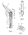
- the axis 30 may be made differently and in particular be split axially, as illustrated in FIG. figure 5 .
- the gripping portion 20 can be made with a cylindrical body of revolution about the Y axis, being provided at its lower end with a flange 39 on which the axle 30 can snap.
- the cylindrical body can be closed at its upper end by a plug, as illustrated.
- the gripping portion 20 may be made with a shaft arranged to snap into a corresponding opening in the base portion, as shown in FIG. figure 6 . It can be seen in this figure that the gripping member 20 may comprise a split shaft 40 capable of snapping into a circular opening 42 of the base portion 10.
- the gripping portion 20 can still be made with fins 45 as can be seen on the Figures 7 and 8 .
- These fins 45 may be connected to a body 46 which may comprise at its lower end a housing 47 in which the shaft 30 can be snapped, as has been shown more particularly in FIG. figure 9 .
- the fins 45 can come by their base 45a bearing against the inclined surface 31 of the base portion 10, in order to slow the rotation of the gripping portion 20 relative to the base portion 10.
- the base portion may be made with at least one boss 48 whose crossing by the fins 45 is noticeable to the user, which may facilitate the positioning if necessary by the latter of the gripping part in the desired position.
- the gripping portion can be mounted with a slight play on the base portion to facilitate the crossing of such a positioning relief.
- the gripping portion 20 can still be made, as illustrated on the figure 10 , in one piece with a housing 50 provided at one end with a flange 51 on which can snap the axis 30.
- This housing 50 can open out through an opening 52, which can be closed if necessary by a plug not shown.
- the axle 30 can be split and an immobilizing pin 54 can be engaged inside.
- the axis 30 can still be riveted, as illustrated in FIG. figure 11 .
- the gripping portion 20 and the base portion 10 can be made as shown in FIG. figure 12 with graduations 55 on one and at least one marker 56 on the other, so as to allow the user to accurately locate the angular orientation of the gripping portion 20 relative to the base portion 10.
- the gripping portion 20 may be made with other forms as well as those illustrated in the figures which have just been described and by way of example, it is shown in FIG. figure 13 a non-symmetrical gripping portion of revolution about the Y axis, having at least one concave edge 57.
- the container may be made otherwise than with a cylindrical body and by way of example is shown in FIG. figure 14 a container 2 having a generally frustoconical body, flared upwardly.
- the container 2 may be provided at its upper end with an insert 58 having a threaded neck and carrying a wiper member consisting for example of a block of a foam.
- the device for packaging and applying the Figures 1 to 4 can be used for example in the following manner.
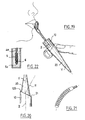
- the user can wear the eyelashes with the rod 4 substantially horizontal, as shown in FIG. figure 15 , the brush can, if necessary, be driven on itself in rotation, to facilitate the penetration of the eyelashes between the bristles of the brush and smooth the product on the eyelashes.
- the user can then make up the eyelashes with the end of the brush, in particular to separate them, after having subjected the gripping portion 20 to rotate 180 ° relative to the base portion, so that the angle ⁇ formed between the Z and Y axes is maximal.
- the user can then use the brush with the rod 4 substantially vertical, as illustrated on the figure 16 . It may be noted in this figure that the free end 5a of the brush is located on the same side as the gripping portion 20.
- the invention is not limited to the makeup of the eyelashes and eyebrows and it is possible to use an applicator according to the invention, in particular for the makeup of the eyelids, as illustrated in FIG. figure 17 , or lips as illustrated on the figures 18 and 19 .
- an applicator according to the invention in particular for the makeup of the eyelids, as illustrated in FIG. figure 17 , or lips as illustrated on the figures 18 and 19 .
- the gripping portion 20 can be made as illustrated in FIG. figure 20 so as not to come into continuity with the base portion 10, a shoulder 100 being formed at the junction of the two.
- Such an arrangement makes it possible, for example, not to have the intersecting Z and R axes at the inclined surface 31.
- the outside diameter of the base portion is greater than that of the adjacent end of the gripping portion.
- the Y and R axes may also be non-intersecting at this inclined surface 31.
- the application element may have a flocking on its surface.
- the application element could still be a comb as shown in figure 21 , a brush to non-twisted core or capillary retention applicator.
- the application element could be made of a cellular and / or elastomeric material, in particular a foam.
- the device can be arranged to place it in a microwave oven to raise the temperature of the product, if necessary.
- the base portion as well as the gripping portion, could be of non-circular section, for example oval or prismatic.
Landscapes
- Engineering & Computer Science (AREA)
- Mechanical Engineering (AREA)
- Coating Apparatus (AREA)
- Brushes (AREA)
- Containers And Packaging Bodies Having A Special Means To Remove Contents (AREA)
Claims (30)
- Vorrichtung zur Konditionierung und zur Auftragung umfassend:einen Behälter (2) und Applikator (3), der abnehmbar auf dem Behälter (2) befestigt werden kann, wobei dieser Applikator umfasst:- einen Grundteil (10), welches ein Auftragungselement (5) umfasst,- einen Greifteil (20), der um eine feste Drehachse (R) drehbeweglich auf dem Grundteil montiert ist, wobei dieser Greifteil eine Längsachse (Y) aufweist, wobei dieser Applikator dadurch gekennzeichnet ist, dass die Drehachse (R) und die Längsachse (Y) des Greifteils nicht perpendikular und nicht parallel sind, und der Grundteil des Applikators Mittel zur Befestigung auf dem Behälter aufweist
- Vorrichtung nach Anspruch 1, dadurch gekennzeichnet, dass die Drehachse (R) des Applikators und eine Längsachse (Z) des Grundteils des Applikators nicht senkrecht zueinander sind.
- Vorrichtung nach einem der vorhergehenden Ansprüche, dadurch gekennzeichnet, dass der Grundteil (10) des Applikators und der Greifteil (20) des Applikators derart miteinander zusammenwirken, dass der Benutzer in der Lage ist den Greifteil in mindestens einer relativ zum Grundteil vorbestimmten Stellung, vorzugsweise in mindestens zwei vorbestimmten Stellungen, zu blockieren
- Vorrichtung nach einem der vorhergehenden Ansprüche, dadurch gekennzeichnet, dass der Greifteil (20) des Applikators und der Grundteil (10) des Applikators derart miteinander zusammenwirken, dass sie bei Erreichen einer vorbestimmten Stellung des Greifteils relativ zum Grundteils, ein Klickgeräusch erzeugen.
- Vorrichtung nach einem der vorhergehenden Ansprüche, dadurch gekennzeichnet, dass der Grundteil (10) des Applikators auch als Verschlusskapsel des Behälters (2) dient.
- Vorrichtung nach dem vorhergehenden Anspruch, dadurch gekennzeichnet, dass der Grundteil (10) des Applikators zur Befestigung, insbesondere durch Verschrauben, an einem Hals (8) des Behälters ausgeführt ist
- Vorrichtung nach einem der Ansprüche 1 bis 6, dadurch gekennzeichnet, dass der Greifteil (20) des Applikators und der Grundteil (10) des Applikators derart ausgeführt sind, dass der Benutzer den Grundteil (10) relativ zum Greifteil (20) einhändig bewegen kann.
- Vorrichtung nach einem der vorhergehenden Ansprüche, dadurch gekennzeichnet, dass mindestens einer von dem Grundteil (10) des Applikators oder dem Greifteil des Applikators auf der Außenseite mindestens ein Relief (10a) zur Reduzierung des Gleitens aufweist.
- Vorrichtung nach einem der vorhergehenden Ansprüche, dadurch gekennzeichnet, dass mindestens einer von dem Grundteil (10) des Applikators oder dem Greifteil des Applikators zumindest teilweise aus einem Werkstoff, der ein gutes Greifen begünstigt, insbesondere aus einem gleitfesten Werkstoff wie einem Elastomer ausgeführt ist.
- Vorrichtung nach einem der vorhergehenden Ansprüche, dadurch gekennzeichnet, dass der Grundteil (10) des Applikators eine Fläche (31) aufweist, die relativ zur Achse (Z) des Grundteils (10) geneigt ist, und gegen die der Greifteil (20) des Applikators anliegt, wobei die Drehachse (R) senkrecht zu dieser geneigten Fläche ausgerichtet ist
- Vorrichtung nach einem der vorhergehenden Ansprüche, dadurch gekennzeichnet, dass wenigstens ein Relief (37, 38; 48) auf mindestens einer der dem Grundteil (10) des Applikators und dem Greifteil (20) des Applikators gegenüberliegenden Flächen ausgeführt ist, um dem Benutzer das Blockieren des Greifteils (20) in einer relativ zum Grundteil (10) vorbestimmten Winkelstellung zu erleichtern.
- Vorrichtung nach einem der vorhergehenden Ansprüche, dadurch gekennzeichnet, dass mindestens einer von dem Grundteil (10) des Applikators oder dem Greifteil (20) des Applikators eine Achse (30; 40) aufweist, die in einer Aufnahme in dem anderen von dem Grundteil (10) oder dem Greifteil (20) des Applikators eingeführt ist.
- Vorrichtung nach Anspruch 12, dadurch gekennzeichnet, dass der Grundteil (10) des Applikators mit einer Achse (30) ausgeführt ist.
- Vorrichtung nach Anspruch 13, dadurch gekennzeichnet, dass die Achse (30) des Applikators an einem Ende mit einem Absatz (30a) ausgestattet ist, um in eine entsprechende Öffnung (35) in dem Greifteil des Applikators einzugreifen.
- Vorrichtung nach einem der Ansprüche 12 bis 14, dadurch gekennzeichnet, dass die Achse (30) des Applikators gespalten ist.
- Vorrichtung nach einem der vorhergehenden Ansprüche, dadurch gekennzeichnet, dass der Greifteil des Applikators ein Einsatzstück (34) umfasst, das eine Schnappbefestigung des Greifteils (20) auf dem Grundteil (10) des Applikators erlaubt.
- Vorrichtung nach Anspruch 12, dadurch gekennzeichnet, dass der Greifteil des Applikators mit einer Achse (40) ausgeführt ist, die zum Einrasten in einer entsprechenden Öffnung (42) des Grundteils des Applikators ausgeführt ist.
- Vorrichtung nach einem der Ansprüche 12 bis 15, dadurch gekennzeichnet, dass der Greifteil des Applikators mit Flügel (45) und einem Körper (46) ausgeführt ist, an dem die Flügel angebracht sind, wobei dieser Körper eine Aufnahme (47) aufweist, in der eine mit dem Grundteil (10) des Applikators fest verbundene Achse (30) eingeführt ist.
- Vorrichtung nach einem der Ansprüche 12 bis 15, dadurch gekennzeichnet, dass der Greifteil (20) des Applikators einen zylindrischen Körper umfasst, der an einem Ende mit einem Rand (39) ausgestattet ist auf dem eine mit dem Grundteil des Applikators fest verbundene Achse (30) einrasten kann.
- Vorrichtung nach einem der vorhergehenden Ansprüche, dadurch gekennzeichnet, dass mindestens einer von dem Grundteil des Applikators oder dem Greifteil des Applikators mindestens eine Markierung, insbesondere Graduierungen (55) aufweist, und der andere Teil eine Ablesemarke (56) aufweist, die es dem Benutzer erlaubt, die Winkelstellung des Greifteils relativ zum Grundteil zu bestimmen.
- Vorrichtung nach einem der vorhergehenden Ansprüche, dadurch gekennzeichnet, dass der Applikator einen Stift (4) aufweist, der an einem Ende das Auftragangselement trägt und an dem anderen Ende mit dem Grundteil (10) fest verbunden ist.
- Vorrichtung nach einem der vorhergehenden Ansprüche, dadurch gekennzeichnet, dass das Auftragungselement eine Bürste (5) ist.
- Vorrichtung nach Anspruch 22, dadurch gekennzeichnet, dass die Bürste einen nicht geradlinigen Steg (6) aufweist.
- Vorrichtung nach einem der Ansprüche 1 bis 21, dadurch gekennzeichnet, dass das Auftragungselement ein flexibles Ansatzstück, insbesondere ein beflocktes Ansatzstück, ein Schaumstoff oder ein Kamm ist.
- Vorrichtung nach einem der vorhergehenden Ansprüche, dadurch gekennzeichnet, dass das Auftragungselement (5) abnehmbar mit dem Grundteil (10) verbunden ist
- Vorrichtung nach einem der vorhergehenden Ansprüche, dadurch gekennzeichnet, dass das Auftragungselement (5) ein freies Ende aufweist, das sich auf der gleichen Seite wie der Greifteil (20) befindet, wenn der Winkel (ß) zwischen den Achsen (Z) des Grundteils und (Y) des Greifteils maximal ist.
- Vorrichtung nach einem der vorhergehenden Ansprüche, dadurch gekennzeichnet, dass die Mittel zur Befestigung des Greifteils des Applikators auf dem Behälter eine dichte Befestigung erlauben.
- Vorrichtung nach einem der vorhergehenden Ansprüche, dadurch gekennzeichnet, dass der Behälter ein Abstreiforgan (9) aufweist, das zum Abstreifen des Auftragungselements (5) beim Abnehmen des Applikators ausgeführt ist.
- Vorrichtung nach einem der vorhergehenden Ansprüche, wobei die Befestigungsmittel ein Gewinde aufweisen oder eine Befestigung des Grundteils auf dem Behälter durch Einrasten erlauben.
- Verfahren zum Auftragen eines kosmetischen Produkts auf ein Teil des Gesichts oder des Körpers, insbesondere auf die Lippen, die Augenlider, die Wimpern, die Augenbrauen oder die Haare, wobei dieses Verfahren dadurch gekennzeichnet ist, dass es folgende Schritte umfasst:- ein Auftragungselement (5) einer Vorrichtung nach einem der vorhergehenden Ansprüche mit dem Produkt beladen,- zwischen zwei verschiedenen Auftragungsweisen die Orientierung des Grundteils (10) relativ zum Greifteil (20) verändern.
Applications Claiming Priority (2)
| Application Number | Priority Date | Filing Date | Title |
|---|---|---|---|
| FR0302253A FR2851435B1 (fr) | 2003-02-24 | 2003-02-24 | Dispositif de conditionnement et d'application d'un produit cosmetique. |
| FR0302253 | 2003-02-24 |
Publications (2)
| Publication Number | Publication Date |
|---|---|
| EP1452111A1 EP1452111A1 (de) | 2004-09-01 |
| EP1452111B1 true EP1452111B1 (de) | 2014-01-15 |
Family
ID=32749713
Family Applications (1)
| Application Number | Title | Priority Date | Filing Date |
|---|---|---|---|
| EP04290459.9A Expired - Lifetime EP1452111B1 (de) | 2003-02-24 | 2004-02-20 | Vorrichtung zum Speichern und Applizieren eines kosmetischen Produktes |
Country Status (6)
| Country | Link |
|---|---|
| US (1) | US7823593B2 (de) |
| EP (1) | EP1452111B1 (de) |
| JP (1) | JP4085069B2 (de) |
| CN (1) | CN1245124C (de) |
| ES (1) | ES2453971T3 (de) |
| FR (1) | FR2851435B1 (de) |
Families Citing this family (42)
| Publication number | Priority date | Publication date | Assignee | Title |
|---|---|---|---|---|
| FR2882506B1 (fr) | 2005-02-25 | 2007-05-18 | Oreal | Procede de maquillage au moyen d'un applicateur vibrant |
| FR2884121B1 (fr) * | 2005-04-12 | 2007-05-25 | Techpack Int Sa | Applicateur longitudinal a tige articulee |
| US8245716B2 (en) * | 2006-09-11 | 2012-08-21 | Albea Services | Flocked cosmetic applicators, methods of manufacture and dispensers including such applicators |
| US20090194127A1 (en) * | 2008-02-04 | 2009-08-06 | Zen Design Solutions Limited | Adjustable applicator |
| US8251074B2 (en) * | 2008-02-04 | 2012-08-28 | Zen Design Solutions Limited | Adjustable applicator |
| FR2929496B1 (fr) * | 2008-04-08 | 2011-01-28 | Oreal | Applicateur vibrant a orientation selective des vibrations |
| US20100132731A1 (en) | 2008-12-01 | 2010-06-03 | Matthew Waitesmith | Ergonomic Cosmetic Brush |
| FR2939619B1 (fr) * | 2008-12-15 | 2011-02-11 | Oreal | Applicateur pour appliquer un produit sur les matieres keratiniques. |
| DE102009011589B4 (de) * | 2009-03-06 | 2015-02-12 | Rusi Cosmetic Gmbh & Co. Kg | Applikator zum Auftragen einer Flüssigkeit |
| BR112012005250A2 (pt) | 2009-09-16 | 2019-09-24 | Colgate Palmolive Co | sistema de cuidado oral, dispensador de cuidado oral e escova de dentes combinados,e, métodos para aplicar um material de cuidado oral a uma superfície oral e aos dentes |
| US8606426B2 (en) | 2009-10-23 | 2013-12-10 | Academia Sinica | Alignment and anti-drift mechanism |
| FR2951918A1 (fr) * | 2009-11-05 | 2011-05-06 | Oreal | Applicateur comportant une liaison permettant d'incliner la surface d'application |
| KR101528395B1 (ko) | 2009-12-23 | 2015-06-11 | 콜게이트-파아므올리브캄파니 | 구강 관리 시스템 |
| PH12012500882A1 (en) | 2009-12-23 | 2013-01-07 | Colgate Palmolive Co | Oral care system, kit and method |
| KR101513342B1 (ko) | 2009-12-23 | 2015-04-17 | 콜게이트-파아므올리브캄파니 | 구강 관리 시스템 |
| CN102711554B (zh) | 2009-12-23 | 2014-10-29 | 高露洁-棕榄公司 | 口腔护理系统 |
| US8764329B2 (en) | 2010-07-09 | 2014-07-01 | Cosmolab, Inc. | Pivoting mechanical applicator |
| DE202010014794U1 (de) * | 2010-10-27 | 2012-01-30 | Geka Gmbh | Applikator mit Applikation von vorne |
| BR112013014928B1 (pt) | 2010-12-15 | 2020-12-15 | Colgate - Palmolive Company | Distribuidor e sistema de higiene bucal |
| FR2976166B1 (fr) * | 2011-06-08 | 2013-07-05 | Oreal | Applicateur d'eye-liner |
| JP5279886B2 (ja) * | 2011-12-06 | 2013-09-04 | 株式会社 資生堂 | マスカラ塗布具 |
| FR3004623B1 (fr) * | 2013-04-19 | 2015-05-29 | Oreal | Applicateur rotatif avec un systeme de freinage pour l'application d'un mascara |
| US9185960B2 (en) * | 2013-11-08 | 2015-11-17 | Julep Beauty, Inc. | Stylus for cosmetics, nail polish applicator and systems and kits based thereon |
| WO2015069286A1 (en) * | 2013-11-08 | 2015-05-14 | Julep, Inc. | Stylus for cosmetics, nail polish applicator and systems and kits based thereon |
| FR3028728B1 (fr) * | 2014-11-21 | 2018-01-26 | L'oreal | Dispositif de conditionnement et d'application |
| FR3028727B1 (fr) * | 2014-11-21 | 2018-01-26 | L'oreal | Applicateur pour appliquer un produit cosmetique de maquillage ou de soin |
| US10750849B2 (en) | 2015-04-03 | 2020-08-25 | Water Pik, Inc. | Skin cleansing and massaging system |
| FR3034968B1 (fr) * | 2015-04-15 | 2019-06-14 | L'oreal | Mecanisme d'articulation d'un dispositif d'application de produit cosmetique, dispositif, methode d'application et procede de fabrication associes |
| US10045603B2 (en) | 2015-07-01 | 2018-08-14 | Noxell Corporation | Cosmetic applicator assembly |
| KR101816552B1 (ko) | 2015-10-16 | 2018-01-09 | (주)아모레퍼시픽 | 롤링퍼프가 구비된 브러시용 화장도구 |
| FR3043531B1 (fr) * | 2015-11-17 | 2019-05-24 | L'oreal | Applicateur pour l'application d'un produit cosmetique |
| USD828694S1 (en) | 2016-04-04 | 2018-09-18 | Water Pik, Inc. | Handheld skin exfoliator |
| US20180140072A1 (en) * | 2016-11-23 | 2018-05-24 | Capicolor International Cosmetics Ltd. | Cosmetic Applicator |
| USD854654S1 (en) | 2017-11-13 | 2019-07-23 | Water Pik, Inc. | Bracket for a handheld cleansing device |
| USD904039S1 (en) | 2017-11-13 | 2020-12-08 | Water Pik, Inc. | Shower accessory hanger |
| USD861830S1 (en) | 2017-11-13 | 2019-10-01 | Water Pik, Inc. | Handheld cleansing device |
| USD898374S1 (en) * | 2018-07-02 | 2020-10-13 | Water Pik, Inc. | Skin cleansing brush |
| JP7817087B2 (ja) * | 2022-06-07 | 2026-02-18 | 花王株式会社 | 装着具 |
| DE202023102494U1 (de) * | 2023-05-08 | 2023-05-17 | Kuo-Yang Hsu | Haarklammer |
| CN116944933A (zh) * | 2023-07-27 | 2023-10-27 | 沈阳鸿光伟业科技有限公司 | 偏心调整锁紧机构 |
| CN220587721U (zh) * | 2023-08-28 | 2024-03-15 | 浙江卓尔雅美妆有限公司 | 360度可旋转可替换化妆刷刷柄 |
| CN222061619U (zh) * | 2024-03-11 | 2024-11-26 | 波迪卡商业制药有限公司 | 一种笔头可转的画笔 |
Family Cites Families (27)
| Publication number | Priority date | Publication date | Assignee | Title |
|---|---|---|---|---|
| US397028A (en) * | 1889-01-29 | Combination shaving utensil | ||
| US963749A (en) * | 1909-07-06 | 1910-07-12 | Philip Deats | Shaving-mug. |
| US1357679A (en) * | 1920-01-31 | 1920-11-02 | Ball Raymond Henry | Shaving kit |
| US2666222A (en) * | 1950-10-03 | 1954-01-19 | Gordon Don | Cosmetic applying brush |
| US3164856A (en) * | 1962-05-15 | 1965-01-12 | Peter J Samaras | Brush attachment for pressurized containers and discharging or ejecting devices |
| DE2701196B1 (de) | 1977-01-13 | 1978-07-06 | Uni Schrauben Gmbh | Dichtungsstreifen fuer Firstabdeckungen |
| US4370989A (en) * | 1977-08-11 | 1983-02-01 | Taylor Charles H | Applicator for liquid cosmetics |
| US4165755A (en) * | 1977-09-26 | 1979-08-28 | Cassai Gino H | Adjustable mascara wand |
| US4560101A (en) | 1983-06-16 | 1985-12-24 | Cooper Industries, Inc. | Self-locking, removeable tapered tips for soldering and de-soldering tools |
| JPS60113711A (ja) | 1983-11-22 | 1985-06-20 | Honda Motor Co Ltd | サスペンシヨンダンパ− |
| US4922575A (en) * | 1984-03-30 | 1990-05-08 | Riemann Herbert F | Three ribbed torque handle |
| US4594148A (en) | 1984-12-31 | 1986-06-10 | Sun Refining And Marketing Company | Extraction of aromatics with ethyl acetoacetate |
| US4732287A (en) * | 1986-11-17 | 1988-03-22 | R.J.S. Industries, Inc. | Container and applicator for fluids |
| US5137038A (en) * | 1990-12-27 | 1992-08-11 | Maybe Holding Co. | Adjustable curve mascara brush |
| FR2701196B1 (fr) * | 1993-02-09 | 1995-04-21 | Oreal | Applicateur de maquillage ou de produit capillaire. |
| FR2749489B1 (fr) * | 1996-06-07 | 1998-08-07 | Oreal | Brosse a profil plan-convexe |
| DE29614364U1 (de) * | 1996-08-19 | 1996-10-17 | Stange, Dirk, 42275 Wuppertal | Rasierpinsel |
| FR2753056B1 (fr) * | 1996-09-10 | 1998-10-16 | Oreal | Applicateur de maquillage ou de produit de soin |
| US5815875A (en) * | 1997-04-21 | 1998-10-06 | Yamada; Todd H. | Bi-positionable toothbrush |
| FR2771077B1 (fr) | 1997-11-14 | 2000-01-14 | Oreal | Dispositif de conditionnement et d'application comportant un recipient, un applicateur ergonomique et un organe d'essorage |
| US6073298A (en) * | 1998-09-08 | 2000-06-13 | O`Brien; Richard E. | Grout cleaning brush |
| DE19918587A1 (de) * | 1999-04-23 | 2000-11-02 | Nele Kosmetik Gmbh | Applikatoranordnung für pudrige oder halbfeste bzw. halbflüssige kosmetische Massen |
| US6237609B1 (en) * | 1999-09-24 | 2001-05-29 | The Bridgeport Metal Goods Manufacturing Company | Curved longitudinal profile mascara brush |
| JP2001161434A (ja) | 1999-12-07 | 2001-06-19 | Kose Corp | 粘性液状化粧料用容器 |
| US20020039513A1 (en) * | 2000-09-29 | 2002-04-04 | Jeff Pink | Nail polish container and applicator cap |
| US6523548B2 (en) * | 2001-07-20 | 2003-02-25 | Color Access, Inc. | Pouch container insert for a cosmetic package and package made with the same |
| US6760949B2 (en) * | 2002-09-04 | 2004-07-13 | Bruce Kaminstein | Rotating dish brush |
-
2003
- 2003-02-24 FR FR0302253A patent/FR2851435B1/fr not_active Expired - Fee Related
-
2004
- 2004-02-18 US US10/779,725 patent/US7823593B2/en not_active Expired - Fee Related
- 2004-02-20 EP EP04290459.9A patent/EP1452111B1/de not_active Expired - Lifetime
- 2004-02-20 ES ES04290459.9T patent/ES2453971T3/es not_active Expired - Lifetime
- 2004-02-24 CN CN200410005993.8A patent/CN1245124C/zh not_active Expired - Fee Related
- 2004-02-24 JP JP2004047487A patent/JP4085069B2/ja not_active Expired - Fee Related
Also Published As
| Publication number | Publication date |
|---|---|
| JP4085069B2 (ja) | 2008-04-30 |
| US20040182410A1 (en) | 2004-09-23 |
| US7823593B2 (en) | 2010-11-02 |
| FR2851435B1 (fr) | 2006-07-14 |
| EP1452111A1 (de) | 2004-09-01 |
| FR2851435A1 (fr) | 2004-08-27 |
| CN1524474A (zh) | 2004-09-01 |
| CN1245124C (zh) | 2006-03-15 |
| JP2004255185A (ja) | 2004-09-16 |
| ES2453971T3 (es) | 2014-04-09 |
Similar Documents
| Publication | Publication Date | Title |
|---|---|---|
| EP1452111B1 (de) | Vorrichtung zum Speichern und Applizieren eines kosmetischen Produktes | |
| EP3420845B1 (de) | Applikatortrichter für kosmetikprodukt, entsprechender applikator und entsprechende applikatoranordnung | |
| CA2308984C (fr) | Dispositif de conditionnement et d'application d'un produit cosmetique, notamment pour le maquillage des levres | |
| EP0916282B1 (de) | Vorrichtung zum Aufbewahren und Auftragen mit einem Behälter, einem ergonomischen Applikator und einem Abstreifer | |
| EP1917883B1 (de) | Applikator zum Auftragen eines Produkts auf Wimpern oder Augenbrauen | |
| CA2227903C (fr) | Dispositif d'application d'un produit de maquillage de fibres keratiniques, notamment des cils, et ensemble de conditionnement et d'application utilisant un tel dispositif | |
| EP1306029B1 (de) | Vorrichtung zum Aufbewahren bzw. Auftragen eines Produktes auf Wimpern bzw. Augenbrauen und Schminkverfahren | |
| EP1938709B1 (de) | Mascarabürste | |
| EP1504691B1 (de) | Auftragelement und Vorrichtung zum Aufbewahren und zum Auftragen bestehend aus einem solchen Auftragelement | |
| FR2932657A1 (fr) | Brosse a mascara. | |
| EP1935279A1 (de) | Applikator zum Auftragen eines Kosmetikprodukts auf keratinhaltige Stoffe | |
| EP1745717B1 (de) | Vorrichtung zum Aufbewahren und Auftragen eines Produktes | |
| EP2022366A1 (de) | Verpackungs- und Anwendungsvorrichtung, die ein Abstreifelement umfasst, das mit mindestens einem nicht-radialen Schlitz ausgestattet ist | |
| FR3026620A1 (fr) | Applicateur pour l'application d'un produit cosmetique | |
| FR2943227A1 (fr) | Applicateur pour appliquer un produit cosmetique sur les cils ou les sourcils | |
| FR2779041A1 (fr) | Dispositif pour le conditionnement et l'application d'une composition sur les fibres keratiniques | |
| FR2979807A1 (fr) | Applicateur pour appliquer un produit sur les cils ou les sourcils | |
| FR2971923A1 (fr) | Dispositif de conditionnement et d'application d'un produit | |
| FR3058622A1 (fr) | Applicateur pour appliquer un produit cosmetique sur les matieres keratiniques | |
| FR3001368A1 (fr) | Applicateur comportant une tige de profil tridimensionnel | |
| EP1369055B1 (de) | Applikator mit einer Stange, die mit einer Greifvorrichtung durch ein Gelenk verbunden ist | |
| EP1716777B1 (de) | Verpackung und Auftragungsvorrichtung eines kosmetischen Erzeugnisses | |
| FR3025986A1 (fr) | Applicateur de produit cosmetique ou de soin | |
| WO2014102474A2 (fr) | Dispositif d'application d'une composition cosmétique | |
| FR2980677A1 (fr) | Brosse a mascara |
Legal Events
| Date | Code | Title | Description |
|---|---|---|---|
| PUAI | Public reference made under article 153(3) epc to a published international application that has entered the european phase |
Free format text: ORIGINAL CODE: 0009012 |
|
| 17P | Request for examination filed |
Effective date: 20040302 |
|
| AK | Designated contracting states |
Kind code of ref document: A1 Designated state(s): AT BE BG CH CY CZ DE DK EE ES FI FR GB GR HU IE IT LI LU MC NL PT RO SE SI SK TR |
|
| AX | Request for extension of the european patent |
Extension state: AL LT LV MK |
|
| AKX | Designation fees paid |
Designated state(s): AT BE BG CH CY CZ DE DK EE ES FI FR GB GR HU IE IT LI LU MC NL PT RO SE SI SK TR |
|
| 17Q | First examination report despatched |
Effective date: 20071114 |
|
| RBV | Designated contracting states (corrected) |
Designated state(s): AT BE BG CH CY CZ DE DK EE ES FI FR GB GR HU IE IT LI LU MC NL PT RO SE SI SK TR |
|
| GRAP | Despatch of communication of intention to grant a patent |
Free format text: ORIGINAL CODE: EPIDOSNIGR1 |
|
| INTG | Intention to grant announced |
Effective date: 20130913 |
|
| GRAS | Grant fee paid |
Free format text: ORIGINAL CODE: EPIDOSNIGR3 |
|
| GRAA | (expected) grant |
Free format text: ORIGINAL CODE: 0009210 |
|
| AK | Designated contracting states |
Kind code of ref document: B1 Designated state(s): AT BE BG CH CY CZ DE DK EE ES FI FR GB GR HU IE IT LI LU MC NL PT RO SE SI SK TR |
|
| REG | Reference to a national code |
Ref country code: GB Ref legal event code: FG4D Free format text: NOT ENGLISH Ref country code: CH Ref legal event code: EP |
|
| REG | Reference to a national code |
Ref country code: AT Ref legal event code: REF Ref document number: 649393 Country of ref document: AT Kind code of ref document: T Effective date: 20140215 |
|
| REG | Reference to a national code |
Ref country code: IE Ref legal event code: FG4D Free format text: LANGUAGE OF EP DOCUMENT: FRENCH |
|
| REG | Reference to a national code |
Ref country code: DE Ref legal event code: R096 Ref document number: 602004044245 Country of ref document: DE Effective date: 20140227 |
|
| REG | Reference to a national code |
Ref country code: ES Ref legal event code: FG2A Ref document number: 2453971 Country of ref document: ES Kind code of ref document: T3 Effective date: 20140409 |
|
| REG | Reference to a national code |
Ref country code: NL Ref legal event code: VDEP Effective date: 20140115 |
|
| REG | Reference to a national code |
Ref country code: AT Ref legal event code: MK05 Ref document number: 649393 Country of ref document: AT Kind code of ref document: T Effective date: 20140115 |
|
| PG25 | Lapsed in a contracting state [announced via postgrant information from national office to epo] |
Ref country code: PT Free format text: LAPSE BECAUSE OF FAILURE TO SUBMIT A TRANSLATION OF THE DESCRIPTION OR TO PAY THE FEE WITHIN THE PRESCRIBED TIME-LIMIT Effective date: 20140515 Ref country code: NL Free format text: LAPSE BECAUSE OF FAILURE TO SUBMIT A TRANSLATION OF THE DESCRIPTION OR TO PAY THE FEE WITHIN THE PRESCRIBED TIME-LIMIT Effective date: 20140115 Ref country code: CY Free format text: LAPSE BECAUSE OF FAILURE TO SUBMIT A TRANSLATION OF THE DESCRIPTION OR TO PAY THE FEE WITHIN THE PRESCRIBED TIME-LIMIT Effective date: 20140115 Ref country code: FI Free format text: LAPSE BECAUSE OF FAILURE TO SUBMIT A TRANSLATION OF THE DESCRIPTION OR TO PAY THE FEE WITHIN THE PRESCRIBED TIME-LIMIT Effective date: 20140115 Ref country code: AT Free format text: LAPSE BECAUSE OF FAILURE TO SUBMIT A TRANSLATION OF THE DESCRIPTION OR TO PAY THE FEE WITHIN THE PRESCRIBED TIME-LIMIT Effective date: 20140115 Ref country code: SE Free format text: LAPSE BECAUSE OF FAILURE TO SUBMIT A TRANSLATION OF THE DESCRIPTION OR TO PAY THE FEE WITHIN THE PRESCRIBED TIME-LIMIT Effective date: 20140115 |
|
| BERE | Be: lapsed |
Owner name: L'OREAL Effective date: 20140228 |
|
| REG | Reference to a national code |
Ref country code: CH Ref legal event code: PL |
|
| REG | Reference to a national code |
Ref country code: DE Ref legal event code: R097 Ref document number: 602004044245 Country of ref document: DE |
|
| PG25 | Lapsed in a contracting state [announced via postgrant information from national office to epo] |
Ref country code: DK Free format text: LAPSE BECAUSE OF FAILURE TO SUBMIT A TRANSLATION OF THE DESCRIPTION OR TO PAY THE FEE WITHIN THE PRESCRIBED TIME-LIMIT Effective date: 20140115 Ref country code: LI Free format text: LAPSE BECAUSE OF NON-PAYMENT OF DUE FEES Effective date: 20140228 Ref country code: CH Free format text: LAPSE BECAUSE OF NON-PAYMENT OF DUE FEES Effective date: 20140228 Ref country code: RO Free format text: LAPSE BECAUSE OF FAILURE TO SUBMIT A TRANSLATION OF THE DESCRIPTION OR TO PAY THE FEE WITHIN THE PRESCRIBED TIME-LIMIT Effective date: 20140115 Ref country code: MC Free format text: LAPSE BECAUSE OF FAILURE TO SUBMIT A TRANSLATION OF THE DESCRIPTION OR TO PAY THE FEE WITHIN THE PRESCRIBED TIME-LIMIT Effective date: 20140115 Ref country code: EE Free format text: LAPSE BECAUSE OF FAILURE TO SUBMIT A TRANSLATION OF THE DESCRIPTION OR TO PAY THE FEE WITHIN THE PRESCRIBED TIME-LIMIT Effective date: 20140115 Ref country code: CZ Free format text: LAPSE BECAUSE OF FAILURE TO SUBMIT A TRANSLATION OF THE DESCRIPTION OR TO PAY THE FEE WITHIN THE PRESCRIBED TIME-LIMIT Effective date: 20140115 |
|
| PLBE | No opposition filed within time limit |
Free format text: ORIGINAL CODE: 0009261 |
|
| STAA | Information on the status of an ep patent application or granted ep patent |
Free format text: STATUS: NO OPPOSITION FILED WITHIN TIME LIMIT |
|
| PG25 | Lapsed in a contracting state [announced via postgrant information from national office to epo] |
Ref country code: SK Free format text: LAPSE BECAUSE OF FAILURE TO SUBMIT A TRANSLATION OF THE DESCRIPTION OR TO PAY THE FEE WITHIN THE PRESCRIBED TIME-LIMIT Effective date: 20140115 |
|
| REG | Reference to a national code |
Ref country code: IE Ref legal event code: MM4A |
|
| 26N | No opposition filed |
Effective date: 20141016 |
|
| PG25 | Lapsed in a contracting state [announced via postgrant information from national office to epo] |
Ref country code: BE Free format text: LAPSE BECAUSE OF NON-PAYMENT OF DUE FEES Effective date: 20140228 Ref country code: IE Free format text: LAPSE BECAUSE OF NON-PAYMENT OF DUE FEES Effective date: 20140220 |
|
| REG | Reference to a national code |
Ref country code: DE Ref legal event code: R097 Ref document number: 602004044245 Country of ref document: DE Effective date: 20141016 |
|
| PG25 | Lapsed in a contracting state [announced via postgrant information from national office to epo] |
Ref country code: SI Free format text: LAPSE BECAUSE OF FAILURE TO SUBMIT A TRANSLATION OF THE DESCRIPTION OR TO PAY THE FEE WITHIN THE PRESCRIBED TIME-LIMIT Effective date: 20140115 |
|
| REG | Reference to a national code |
Ref country code: FR Ref legal event code: PLFP Year of fee payment: 13 |
|
| PG25 | Lapsed in a contracting state [announced via postgrant information from national office to epo] |
Ref country code: BG Free format text: LAPSE BECAUSE OF FAILURE TO SUBMIT A TRANSLATION OF THE DESCRIPTION OR TO PAY THE FEE WITHIN THE PRESCRIBED TIME-LIMIT Effective date: 20140115 |
|
| PG25 | Lapsed in a contracting state [announced via postgrant information from national office to epo] |
Ref country code: GR Free format text: LAPSE BECAUSE OF FAILURE TO SUBMIT A TRANSLATION OF THE DESCRIPTION OR TO PAY THE FEE WITHIN THE PRESCRIBED TIME-LIMIT Effective date: 20140416 |
|
| PG25 | Lapsed in a contracting state [announced via postgrant information from national office to epo] |
Ref country code: LU Free format text: LAPSE BECAUSE OF NON-PAYMENT OF DUE FEES Effective date: 20140220 Ref country code: HU Free format text: LAPSE BECAUSE OF FAILURE TO SUBMIT A TRANSLATION OF THE DESCRIPTION OR TO PAY THE FEE WITHIN THE PRESCRIBED TIME-LIMIT; INVALID AB INITIO Effective date: 20040220 Ref country code: TR Free format text: LAPSE BECAUSE OF FAILURE TO SUBMIT A TRANSLATION OF THE DESCRIPTION OR TO PAY THE FEE WITHIN THE PRESCRIBED TIME-LIMIT Effective date: 20140115 |
|
| REG | Reference to a national code |
Ref country code: FR Ref legal event code: PLFP Year of fee payment: 14 |
|
| REG | Reference to a national code |
Ref country code: FR Ref legal event code: PLFP Year of fee payment: 15 |
|
| PGFP | Annual fee paid to national office [announced via postgrant information from national office to epo] |
Ref country code: DE Payment date: 20200204 Year of fee payment: 17 Ref country code: GB Payment date: 20200212 Year of fee payment: 17 Ref country code: ES Payment date: 20200302 Year of fee payment: 17 Ref country code: IT Payment date: 20200128 Year of fee payment: 17 |
|
| PGFP | Annual fee paid to national office [announced via postgrant information from national office to epo] |
Ref country code: FR Payment date: 20200113 Year of fee payment: 17 |
|
| REG | Reference to a national code |
Ref country code: DE Ref legal event code: R119 Ref document number: 602004044245 Country of ref document: DE |
|
| GBPC | Gb: european patent ceased through non-payment of renewal fee |
Effective date: 20210220 |
|
| PG25 | Lapsed in a contracting state [announced via postgrant information from national office to epo] |
Ref country code: DE Free format text: LAPSE BECAUSE OF NON-PAYMENT OF DUE FEES Effective date: 20210901 Ref country code: FR Free format text: LAPSE BECAUSE OF NON-PAYMENT OF DUE FEES Effective date: 20210228 Ref country code: GB Free format text: LAPSE BECAUSE OF NON-PAYMENT OF DUE FEES Effective date: 20210220 |
|
| PG25 | Lapsed in a contracting state [announced via postgrant information from national office to epo] |
Ref country code: IT Free format text: LAPSE BECAUSE OF NON-PAYMENT OF DUE FEES Effective date: 20210220 |
|
| REG | Reference to a national code |
Ref country code: ES Ref legal event code: FD2A Effective date: 20220513 |
|
| PG25 | Lapsed in a contracting state [announced via postgrant information from national office to epo] |
Ref country code: ES Free format text: LAPSE BECAUSE OF NON-PAYMENT OF DUE FEES Effective date: 20210221 |