EP1452143A2 - Ciseaux, notamment à usage chirurgical - Google Patents
Ciseaux, notamment à usage chirurgical Download PDFInfo
- Publication number
- EP1452143A2 EP1452143A2 EP04013571A EP04013571A EP1452143A2 EP 1452143 A2 EP1452143 A2 EP 1452143A2 EP 04013571 A EP04013571 A EP 04013571A EP 04013571 A EP04013571 A EP 04013571A EP 1452143 A2 EP1452143 A2 EP 1452143A2
- Authority
- EP
- European Patent Office
- Prior art keywords
- metal foil
- scissors according
- projections
- scissors
- cutting
- Prior art date
- Legal status (The legal status is an assumption and is not a legal conclusion. Google has not performed a legal analysis and makes no representation as to the accuracy of the status listed.)
- Granted
Links
- 239000002184 metal Substances 0.000 claims abstract description 85
- 229910052751 metal Inorganic materials 0.000 claims abstract description 85
- 238000005520 cutting process Methods 0.000 claims abstract description 43
- 239000011888 foil Substances 0.000 claims description 78
- 239000004033 plastic Substances 0.000 claims description 14
- 229920003023 plastic Polymers 0.000 claims description 14
- 239000000463 material Substances 0.000 claims description 10
- 239000000853 adhesive Substances 0.000 claims description 7
- 230000001070 adhesive effect Effects 0.000 claims description 7
- PXHVJJICTQNCMI-UHFFFAOYSA-N Nickel Chemical compound [Ni] PXHVJJICTQNCMI-UHFFFAOYSA-N 0.000 claims description 6
- 239000012790 adhesive layer Substances 0.000 claims description 4
- 238000003698 laser cutting Methods 0.000 claims description 4
- 229910000639 Spring steel Inorganic materials 0.000 claims description 3
- 230000003628 erosive effect Effects 0.000 claims description 3
- 238000005530 etching Methods 0.000 claims description 3
- 229910052759 nickel Inorganic materials 0.000 claims description 3
- 239000004831 Hot glue Substances 0.000 claims description 2
- 239000000835 fiber Substances 0.000 claims description 2
- 229920000106 Liquid crystal polymer Polymers 0.000 description 4
- 239000004977 Liquid-crystal polymers (LCPs) Substances 0.000 description 4
- 239000004696 Poly ether ether ketone Substances 0.000 description 4
- 229920002530 polyetherether ketone Polymers 0.000 description 4
- 229920000049 Carbon (fiber) Polymers 0.000 description 2
- 239000004952 Polyamide Substances 0.000 description 2
- 239000004917 carbon fiber Substances 0.000 description 2
- 238000001816 cooling Methods 0.000 description 2
- 230000002349 favourable effect Effects 0.000 description 2
- 239000003365 glass fiber Substances 0.000 description 2
- 238000000227 grinding Methods 0.000 description 2
- 238000010438 heat treatment Methods 0.000 description 2
- 238000004519 manufacturing process Methods 0.000 description 2
- 238000000034 method Methods 0.000 description 2
- 229920002647 polyamide Polymers 0.000 description 2
- 238000004080 punching Methods 0.000 description 2
- 235000011299 Brassica oleracea var botrytis Nutrition 0.000 description 1
- 240000003259 Brassica oleracea var. botrytis Species 0.000 description 1
- 0 C1CC*CC1 Chemical compound C1CC*CC1 0.000 description 1
- 239000004838 Heat curing adhesive Substances 0.000 description 1
- 238000004026 adhesive bonding Methods 0.000 description 1
- 239000002390 adhesive tape Substances 0.000 description 1
- 230000009286 beneficial effect Effects 0.000 description 1
- 230000000295 complement effect Effects 0.000 description 1
- 238000010276 construction Methods 0.000 description 1
- 230000008021 deposition Effects 0.000 description 1
- 230000000694 effects Effects 0.000 description 1
- 238000009434 installation Methods 0.000 description 1
- 230000001788 irregular Effects 0.000 description 1
- 238000005304 joining Methods 0.000 description 1
- 150000002739 metals Chemical class 0.000 description 1
- 238000012805 post-processing Methods 0.000 description 1
- 238000012545 processing Methods 0.000 description 1
- 238000009958 sewing Methods 0.000 description 1
- 238000010008 shearing Methods 0.000 description 1
- 229920001169 thermoplastic Polymers 0.000 description 1
- 239000004416 thermosoftening plastic Substances 0.000 description 1
Images


Classifications
-
- A—HUMAN NECESSITIES
- A61—MEDICAL OR VETERINARY SCIENCE; HYGIENE
- A61B—DIAGNOSIS; SURGERY; IDENTIFICATION
- A61B17/00—Surgical instruments, devices or methods
- A61B17/32—Surgical cutting instruments
- A61B17/3201—Scissors
-
- A—HUMAN NECESSITIES
- A61—MEDICAL OR VETERINARY SCIENCE; HYGIENE
- A61B—DIAGNOSIS; SURGERY; IDENTIFICATION
- A61B17/00—Surgical instruments, devices or methods
- A61B17/28—Surgical forceps
- A61B17/2812—Surgical forceps with a single pivotal connection
- A61B17/282—Jaws
- A61B2017/2825—Inserts of different material in jaws
Definitions
- the invention relates to a pair of scissors, in particular for surgical Purposes, with two mutually pivotable branches, the front end each having a cutting portion with a cutting edge and at the rear end each having a handle portion, wherein at least one of the branches in their cutting section on their the Other industry facing inner surface with a flat against her Metal foil is connected, at least on the cutting edge side End of the inner surface extends to this or slightly protruding above and at this end of the inner surface arranged edge forms the cutting edge of this inner surface.
- US-A-3052026 shows such a pair of scissors.
- Surgical scissors are widely used, for example in the surgical area for cutting tissue, drapes, of sewing threads etc., and in all cases it is important that an effective and sharp cutting edge is available. It is therefore common to grind these scissors, this operation is complex and of Success of this operation depends on whether the scissors for the purpose is usable or not.
- the metal foil has a thickness between 0.05 and 0.4 mm and that the metal foil with the inner surface the industry is glued.
- the metal foil can be made of different metals, Particularly advantageous is the use of a metal foil made of spring steel.
- the metal foil made of a metal a high hardness, for example, a hardness of at least HRC60.
- the metal foil can be made in various ways, for example, the metal foil may be a stamped part or a laser cutting part or a wire EDM part. In all cases, the metal foil from a worked out larger flat metal foil and can then after this working out, for example, by punching, laser cutting or wire eroding can be used directly, a post-processing is no longer necessary.
- metal foil can be between metal foil and inner surface of a thermally polymerizable adhesive disposed his or a hot melt adhesive.
- a double-sided adhesive surface is arranged, for example a double sided tape, as used for fixing brake discs used in the automotive industry.
- the metal foil in another way with the inner surface of the industry too connect, for example, the metal foil welded to the industry or soldered, when using plastic as Material of the industry, the metal foil can also injected into the plastic be.
- the film surface on the the inner surface facing side is structured so that in this Area a particularly intimate connection between the material of Industry and the metal foil is achieved.
- the metal foil on its the inner surface of the industry facing side projections that carry in the material of the Immerse industry preferably, the projections to undercuts on.
- the structure of the projections may be cauliflower-like be, while the projections over the metal foil are distributed irregularly and form spherical or approximately spherical projections, the connected via stalk-like connections with the metal foil.
- Such projections can, for example, by an electrolytic be formed on the film applied adhesive layer.
- the projections exist made of nickel.
- metal foil and the inner surface the industry are connected by hot stamping.
- hot stamping will undermine the metal foil and the industry Pressure and possibly additional heating pressed against each other, while the projections penetrate into the plastic material of the Industry, and this plastic material can flow around the projections, so that after cooling a toothed connection between metal foil and industry results.
- the cutting edge of the metal foil may be smooth, according to However, a preferred embodiment is provided that the Cutting edge of the metal foil forming edge adjacent Has projections and recesses, in particular tooth-shaped front and Recesses. This results in a similar effect as in a serration, the sliding of the between the cutting edges arranged and to be cut part is prevented.
- the inner surface towards the opposite branch carries raised projections which engage in cutouts of the metal foil and thereby position them on the inner surface.
- a projection may, for example, at the opposite of the cutting edge Be arranged edge of the inner surface, it is there advantageous when the projection is parallel to the edge of the inner surface extends over part of the length of this edge.
- the cutting sections an entanglement exhibit.
- the Cutting sections slightly pivoted about their longitudinal axis against each other, so that they enclose a small angle with each other, As a result, the inner surfaces are not flat against each other, but generate a kind of clearance angle, as in conventional scissors through a certain grinding of the cutting edges can be achieved.
- scissors at Industries are used with different materials, so also with metal shears, such a configuration is particularly advantageous but with a pair of scissors whose branches are made of plastic.
- scissors can be produced as Industry material Use plastics that are not suitable ones Form cutting edges, by laying the described
- metal foils on the inner surfaces it is possible to produce scissors, which consist almost entirely of plastic and still outstanding Have cutting properties.
- plastics for example Polyamides (PA, PPA), polyetheretherketone (PEEK) or Liquid crystal polymers (LCP) are used, it is beneficial when the plastic is reinforced with fibers, for example glass fibers or with carbon fibers.
- PPA Polyamides
- PEEK polyetheretherketone
- LCP Liquid crystal polymers
- the inner surfaces of the branches with the metal foil can move in the direction on their grip sections to over the pivotal connection of the branches extend, in particular, the pivotal connection in the middle part the inner surfaces provided with the metal foil, so that the pivotal connection press the two inner surfaces resiliently against each other can.
- the scissors 1 shown in the drawing comprises two branches 2, 3, which are pivotally connected to each other at a pivot bearing 4 are.
- This pivot bearing is in the illustrated embodiment formed by a bearing pin 5 passing through an industry 2, which moves from this industry 2 towards the other industry 3.
- the other industry 3 has a bearing opening in this area 6, in which the bearing pin 5 engages.
- a laterally projecting Lappets 7 arranged, which overlaps the industry 3, if both branches 2, 3 parallel to each other in the closed position, as it is in Figure 1 is shown in solid lines.
- the Bearing pin 5 formed as a separate component, but it can also be in one piece be trained with the industry 2.
- Each of the two branches 2, 3 has a cutting section 8, the is arranged at the front end of the branches 2, 3, a handle portion 9 with finger lugs 10 at the opposite end and one Connecting portion 11 between cutting section 8 and handle portion 9th
- the pivot bearing 4 is located approximately in the middle of the longitudinal extent of these inner surfaces 12, and the cutting sections 8 of the two branches 2, 3 are through the pivot bearing 4 and the flap 7 elastically pressed against each other, so that thereby the width of the slot 13 is reduced.
- the two branches 2 and 3 are each integrally formed and made made of plastic, for example polyamide (PA, PPA) made of polyetheretherketone (PEEK) or a liquid crystal polymer (LCP), preferably is this plastic by embedding fibrous Reinforced materials, such as glass fibers or carbon fibers.
- PPA polyamide
- PEEK polyetheretherketone
- LCP liquid crystal polymer
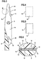
- a metal foil 14 is placed flat, this metal foil 14 is glued to the inner surface 12, for example by interposition of a double-sided adhesive tape 15th ( Figure 6), which with a heat-curing adhesive can be coated.
- the metal foil 14 is made of a metal of high hardness, in particular with a hardness of at least HRC60, it is favorable as a metal one Spring steel to use.
- the thickness of the metal foil 14 is between 0.05 and 0.4 mm.
- the shape of the metal foil 14 corresponds to the Shape of the inner surface 12, the metal foil is aligned with the side edge the inner surface 12 or is at most slightly above it, being that when opening the branches 2, 3 together sliding edges of the metal foils 14, the cutting edges 16 of the scissors Train 1.
- the metal foils 14 are machined from a larger metal foil, for example, by punching, by wire erosion or by Laser cutting, and can be applied to the inner surfaces without further processing 12 are placed and connected with these by gluing.
- the metal foils 14 In order to achieve a good positioning of the metal foils 14, have the inner surfaces 12 raised projections 17, 18, which in the direction projecting on the inner surface of the opposite branch and in the complementary recesses 19 and 20 of the metal foil 14 intervene.
- a projection 17 runs at the cutting edge 16 opposite Edge of the inner surface 12 along and extends over a part of the length of this edge, the other projection 18 is on arranged on the handle portion end of the inner surface 12 and in Direction to the front end of the scissors 1 wedge-shaped, so that when laying the metal foil 14 on the inner surface 12 already by the projections 17 and 18 an exact alignment of the metal foil relative to the inner surface 12 results. In this situation can then the Bonding done.
- the formed by the metal foil 14 cutting edge 16 can be smooth be formed ( Figure 4) or in a modified embodiment tooth-shaped ( Figure 5), so that thereby the to be cut Well held between the cutting edges 16 and against slipping is secured.
- the bonding of the metal foil 14 with the inner surface 12 is effected by means of an adhesive which is activated by heat, This is the case for industries made of thermoplastic be made possible, the bonding in the manufacturing process industries or immediately thereafter, with the Educational heat of industries used to activate the adhesive becomes.
- connection between metal foil and the inner surface of the industry can be further improved by the metal foil 14 on her the inner surface 12 of the branches 2, 3 side facing projections 21 carries, which preferably have undercuts 22. It is about usually a microstructure shown in FIGS. 7 and 8 is shown very enlarged.
- the projections can be completely irregular be distributed over the surface of the metal foil 14, for example, the structure may be cauliflower, i. the projections 21 have a spherical or generally convex outer surface 21 and are connected via a stalk-like connection 24 with the metal foil 14.
- This surface structure can be achieved, for example, by an etching process be produced or particularly advantageous by an electrolytic Deposition of an adhesive layer on the metal foil, in particular a Adhesive layer of nickel.
Landscapes
- Health & Medical Sciences (AREA)
- Surgery (AREA)
- Life Sciences & Earth Sciences (AREA)
- Medical Informatics (AREA)
- Animal Behavior & Ethology (AREA)
- Engineering & Computer Science (AREA)
- Biomedical Technology (AREA)
- Heart & Thoracic Surgery (AREA)
- Pathology (AREA)
- Molecular Biology (AREA)
- Nuclear Medicine, Radiotherapy & Molecular Imaging (AREA)
- General Health & Medical Sciences (AREA)
- Public Health (AREA)
- Veterinary Medicine (AREA)
- Scissors And Nippers (AREA)
- Surgical Instruments (AREA)
- Acyclic And Carbocyclic Compounds In Medicinal Compositions (AREA)
- Laminated Bodies (AREA)
Applications Claiming Priority (3)
| Application Number | Priority Date | Filing Date | Title |
|---|---|---|---|
| DE10138356 | 2001-08-04 | ||
| DE10138356A DE10138356A1 (de) | 2001-08-04 | 2001-08-04 | Schere, insbesondere für chirurgische Zwecke |
| EP20020753086 EP1411843B1 (fr) | 2001-08-04 | 2002-07-27 | Ciseaux, notamment a usage chirurgical |
Related Parent Applications (1)
| Application Number | Title | Priority Date | Filing Date |
|---|---|---|---|
| EP02753086.4 Division | 2002-07-27 |
Publications (3)
| Publication Number | Publication Date |
|---|---|
| EP1452143A2 true EP1452143A2 (fr) | 2004-09-01 |
| EP1452143A3 EP1452143A3 (fr) | 2004-09-29 |
| EP1452143B1 EP1452143B1 (fr) | 2005-09-21 |
Family
ID=7694420
Family Applications (2)
| Application Number | Title | Priority Date | Filing Date |
|---|---|---|---|
| EP04013571A Expired - Lifetime EP1452143B1 (fr) | 2001-08-04 | 2002-07-27 | Ciseaux, notamment à usage chirurgical |
| EP20020753086 Expired - Lifetime EP1411843B1 (fr) | 2001-08-04 | 2002-07-27 | Ciseaux, notamment a usage chirurgical |
Family Applications After (1)
| Application Number | Title | Priority Date | Filing Date |
|---|---|---|---|
| EP20020753086 Expired - Lifetime EP1411843B1 (fr) | 2001-08-04 | 2002-07-27 | Ciseaux, notamment a usage chirurgical |
Country Status (6)
| Country | Link |
|---|---|
| US (1) | US20040193200A1 (fr) |
| EP (2) | EP1452143B1 (fr) |
| AT (2) | ATE304816T1 (fr) |
| DE (3) | DE10138356A1 (fr) |
| ES (2) | ES2249748T3 (fr) |
| WO (1) | WO2003013376A1 (fr) |
Cited By (1)
| Publication number | Priority date | Publication date | Assignee | Title |
|---|---|---|---|---|
| US10342598B2 (en) | 2012-08-15 | 2019-07-09 | Ethicon Llc | Electrosurgical system for delivering a biphasic waveform |
Families Citing this family (60)
| Publication number | Priority date | Publication date | Assignee | Title |
|---|---|---|---|---|
| DE10328512A1 (de) | 2003-06-20 | 2005-01-13 | Aesculap Ag & Co. Kg | Chirurgisches Instrument |
| DE102004052515B4 (de) * | 2004-10-22 | 2019-01-03 | Aesculap Ag | Chirurgische Schere und Verfahren zum Herstellen einer chirurgischen Schere |
| US20070012319A1 (en) * | 2005-03-14 | 2007-01-18 | Sandra Frascati | Jaw exerciser |
| US7655004B2 (en) | 2007-02-15 | 2010-02-02 | Ethicon Endo-Surgery, Inc. | Electroporation ablation apparatus, system, and method |
| US7815662B2 (en) | 2007-03-08 | 2010-10-19 | Ethicon Endo-Surgery, Inc. | Surgical suture anchors and deployment device |
| US8075572B2 (en) | 2007-04-26 | 2011-12-13 | Ethicon Endo-Surgery, Inc. | Surgical suturing apparatus |
| US8100922B2 (en) | 2007-04-27 | 2012-01-24 | Ethicon Endo-Surgery, Inc. | Curved needle suturing tool |
| US8579897B2 (en) | 2007-11-21 | 2013-11-12 | Ethicon Endo-Surgery, Inc. | Bipolar forceps |
| US8568410B2 (en) | 2007-08-31 | 2013-10-29 | Ethicon Endo-Surgery, Inc. | Electrical ablation surgical instruments |
| US8262655B2 (en) | 2007-11-21 | 2012-09-11 | Ethicon Endo-Surgery, Inc. | Bipolar forceps |
| US20090112059A1 (en) | 2007-10-31 | 2009-04-30 | Nobis Rudolph H | Apparatus and methods for closing a gastrotomy |
| US8480657B2 (en) | 2007-10-31 | 2013-07-09 | Ethicon Endo-Surgery, Inc. | Detachable distal overtube section and methods for forming a sealable opening in the wall of an organ |
| US8262680B2 (en) | 2008-03-10 | 2012-09-11 | Ethicon Endo-Surgery, Inc. | Anastomotic device |
| US8114072B2 (en) | 2008-05-30 | 2012-02-14 | Ethicon Endo-Surgery, Inc. | Electrical ablation device |
| US8679003B2 (en) | 2008-05-30 | 2014-03-25 | Ethicon Endo-Surgery, Inc. | Surgical device and endoscope including same |
| US8070759B2 (en) | 2008-05-30 | 2011-12-06 | Ethicon Endo-Surgery, Inc. | Surgical fastening device |
| US8652150B2 (en) | 2008-05-30 | 2014-02-18 | Ethicon Endo-Surgery, Inc. | Multifunction surgical device |
| US8317806B2 (en) | 2008-05-30 | 2012-11-27 | Ethicon Endo-Surgery, Inc. | Endoscopic suturing tension controlling and indication devices |
| US8771260B2 (en) | 2008-05-30 | 2014-07-08 | Ethicon Endo-Surgery, Inc. | Actuating and articulating surgical device |
| US8906035B2 (en) | 2008-06-04 | 2014-12-09 | Ethicon Endo-Surgery, Inc. | Endoscopic drop off bag |
| US8403926B2 (en) | 2008-06-05 | 2013-03-26 | Ethicon Endo-Surgery, Inc. | Manually articulating devices |
| US8361112B2 (en) | 2008-06-27 | 2013-01-29 | Ethicon Endo-Surgery, Inc. | Surgical suture arrangement |
| US8888792B2 (en) | 2008-07-14 | 2014-11-18 | Ethicon Endo-Surgery, Inc. | Tissue apposition clip application devices and methods |
| US8262563B2 (en) | 2008-07-14 | 2012-09-11 | Ethicon Endo-Surgery, Inc. | Endoscopic translumenal articulatable steerable overtube |
| US8211125B2 (en) | 2008-08-15 | 2012-07-03 | Ethicon Endo-Surgery, Inc. | Sterile appliance delivery device for endoscopic procedures |
| US8529563B2 (en) | 2008-08-25 | 2013-09-10 | Ethicon Endo-Surgery, Inc. | Electrical ablation devices |
| US8241204B2 (en) | 2008-08-29 | 2012-08-14 | Ethicon Endo-Surgery, Inc. | Articulating end cap |
| US8480689B2 (en) | 2008-09-02 | 2013-07-09 | Ethicon Endo-Surgery, Inc. | Suturing device |
| US8409200B2 (en) | 2008-09-03 | 2013-04-02 | Ethicon Endo-Surgery, Inc. | Surgical grasping device |
| US8114119B2 (en) | 2008-09-09 | 2012-02-14 | Ethicon Endo-Surgery, Inc. | Surgical grasping device |
| US8337394B2 (en) | 2008-10-01 | 2012-12-25 | Ethicon Endo-Surgery, Inc. | Overtube with expandable tip |
| US8157834B2 (en) | 2008-11-25 | 2012-04-17 | Ethicon Endo-Surgery, Inc. | Rotational coupling device for surgical instrument with flexible actuators |
| US8172772B2 (en) | 2008-12-11 | 2012-05-08 | Ethicon Endo-Surgery, Inc. | Specimen retrieval device |
| US8361066B2 (en) | 2009-01-12 | 2013-01-29 | Ethicon Endo-Surgery, Inc. | Electrical ablation devices |
| US8828031B2 (en) | 2009-01-12 | 2014-09-09 | Ethicon Endo-Surgery, Inc. | Apparatus for forming an anastomosis |
| US9226772B2 (en) | 2009-01-30 | 2016-01-05 | Ethicon Endo-Surgery, Inc. | Surgical device |
| US8252057B2 (en) | 2009-01-30 | 2012-08-28 | Ethicon Endo-Surgery, Inc. | Surgical access device |
| US8037591B2 (en) | 2009-02-02 | 2011-10-18 | Ethicon Endo-Surgery, Inc. | Surgical scissors |
| US20110098704A1 (en) | 2009-10-28 | 2011-04-28 | Ethicon Endo-Surgery, Inc. | Electrical ablation devices |
| US8608652B2 (en) | 2009-11-05 | 2013-12-17 | Ethicon Endo-Surgery, Inc. | Vaginal entry surgical devices, kit, system, and method |
| US8353487B2 (en) | 2009-12-17 | 2013-01-15 | Ethicon Endo-Surgery, Inc. | User interface support devices for endoscopic surgical instruments |
| US8496574B2 (en) | 2009-12-17 | 2013-07-30 | Ethicon Endo-Surgery, Inc. | Selectively positionable camera for surgical guide tube assembly |
| US8506564B2 (en) | 2009-12-18 | 2013-08-13 | Ethicon Endo-Surgery, Inc. | Surgical instrument comprising an electrode |
| US9028483B2 (en) | 2009-12-18 | 2015-05-12 | Ethicon Endo-Surgery, Inc. | Surgical instrument comprising an electrode |
| US9005198B2 (en) | 2010-01-29 | 2015-04-14 | Ethicon Endo-Surgery, Inc. | Surgical instrument comprising an electrode |
| US10092291B2 (en) | 2011-01-25 | 2018-10-09 | Ethicon Endo-Surgery, Inc. | Surgical instrument with selectively rigidizable features |
| US9233241B2 (en) | 2011-02-28 | 2016-01-12 | Ethicon Endo-Surgery, Inc. | Electrical ablation devices and methods |
| US9314620B2 (en) | 2011-02-28 | 2016-04-19 | Ethicon Endo-Surgery, Inc. | Electrical ablation devices and methods |
| US9254169B2 (en) | 2011-02-28 | 2016-02-09 | Ethicon Endo-Surgery, Inc. | Electrical ablation devices and methods |
| US9049987B2 (en) | 2011-03-17 | 2015-06-09 | Ethicon Endo-Surgery, Inc. | Hand held surgical device for manipulating an internal magnet assembly within a patient |
| US8986199B2 (en) | 2012-02-17 | 2015-03-24 | Ethicon Endo-Surgery, Inc. | Apparatus and methods for cleaning the lens of an endoscope |
| US9427255B2 (en) | 2012-05-14 | 2016-08-30 | Ethicon Endo-Surgery, Inc. | Apparatus for introducing a steerable camera assembly into a patient |
| US9078662B2 (en) | 2012-07-03 | 2015-07-14 | Ethicon Endo-Surgery, Inc. | Endoscopic cap electrode and method for using the same |
| US9545290B2 (en) | 2012-07-30 | 2017-01-17 | Ethicon Endo-Surgery, Inc. | Needle probe guide |
| US9572623B2 (en) | 2012-08-02 | 2017-02-21 | Ethicon Endo-Surgery, Inc. | Reusable electrode and disposable sheath |
| US10314649B2 (en) | 2012-08-02 | 2019-06-11 | Ethicon Endo-Surgery, Inc. | Flexible expandable electrode and method of intraluminal delivery of pulsed power |
| US10098527B2 (en) | 2013-02-27 | 2018-10-16 | Ethidcon Endo-Surgery, Inc. | System for performing a minimally invasive surgical procedure |
| USD1123543S1 (en) * | 2024-03-01 | 2026-04-28 | Fiskars Finland Oy Ab | Plant snips |
| USD1123542S1 (en) * | 2024-03-01 | 2026-04-28 | Fiskars Finland Oy Ab | Plant snips |
| USD1123544S1 (en) * | 2024-03-01 | 2026-04-28 | Fiskars Finland Oy Ab | Plant snips |
Family Cites Families (12)
| Publication number | Priority date | Publication date | Assignee | Title |
|---|---|---|---|---|
| DE848165C (de) * | 1943-11-09 | 1952-09-01 | Erwin Krusius | Schere |
| US2511187A (en) * | 1946-10-16 | 1950-06-13 | Philbeck Corp | Shears |
| US2627656A (en) * | 1947-02-06 | 1953-02-10 | Richartz Paul | Scissors with twist in each blade |
| US3052026A (en) * | 1960-09-29 | 1962-09-04 | Richards Bros & Sons Ltd | Scissors, shears and like implements |
| US4048721A (en) * | 1976-09-10 | 1977-09-20 | Russell (Shears) Limited | Scissors |
| IT7722375U1 (it) * | 1977-09-27 | 1979-03-27 | Marin Sergio | Forbice o simile utensile da taglio con bracci in materiale plastico |
| DE3219260A1 (de) * | 1982-05-21 | 1983-11-24 | Lawton GmbH & Co KG, 7200 Tuttlingen | Verfahren zum einbringen eines harten materials in den ausgesparten beanspruchungsbereich des grundkoerpers eines chirurgischen instruments und chirurgisches instrument |
| WO1998016355A1 (fr) * | 1996-10-16 | 1998-04-23 | Steffen Homann | Instrument de coupe chauffant, notamment une paire de ciseaux, un couteau, une tondeuse a cheveux ou equivalent |
| US5891140A (en) * | 1996-12-23 | 1999-04-06 | Cardiothoracic Systems, Inc. | Electrosurgical device for harvesting a vessel especially the internal mammary artery for coronary artery bypass grafting |
| DE19733035A1 (de) * | 1997-07-31 | 1999-02-18 | Aesculap Ag & Co Kg | Schere für medizinische Zwecke |
| DE29713631U1 (de) * | 1997-07-31 | 1997-10-02 | Aesculap AG & Co. KG, 78532 Tuttlingen | Chirurgisches Instrument |
| DE19908367C1 (de) * | 1999-02-26 | 2000-03-30 | Wella Ag | Schere und Verfahren zum Schleifen der Schere |
-
2001
- 2001-08-04 DE DE10138356A patent/DE10138356A1/de not_active Withdrawn
-
2002
- 2002-07-27 DE DE50201419T patent/DE50201419D1/de not_active Expired - Lifetime
- 2002-07-27 DE DE50204347T patent/DE50204347D1/de not_active Expired - Lifetime
- 2002-07-27 AT AT04013571T patent/ATE304816T1/de not_active IP Right Cessation
- 2002-07-27 WO PCT/EP2002/008389 patent/WO2003013376A1/fr not_active Ceased
- 2002-07-27 EP EP04013571A patent/EP1452143B1/fr not_active Expired - Lifetime
- 2002-07-27 ES ES04013571T patent/ES2249748T3/es not_active Expired - Lifetime
- 2002-07-27 EP EP20020753086 patent/EP1411843B1/fr not_active Expired - Lifetime
- 2002-07-27 ES ES02753086T patent/ES2230509T3/es not_active Expired - Lifetime
- 2002-07-27 AT AT02753086T patent/ATE280538T1/de not_active IP Right Cessation
-
2004
- 2004-01-22 US US10/763,941 patent/US20040193200A1/en not_active Abandoned
Cited By (1)
| Publication number | Priority date | Publication date | Assignee | Title |
|---|---|---|---|---|
| US10342598B2 (en) | 2012-08-15 | 2019-07-09 | Ethicon Llc | Electrosurgical system for delivering a biphasic waveform |
Also Published As
| Publication number | Publication date |
|---|---|
| ATE280538T1 (de) | 2004-11-15 |
| EP1452143B1 (fr) | 2005-09-21 |
| US20040193200A1 (en) | 2004-09-30 |
| WO2003013376A1 (fr) | 2003-02-20 |
| ES2230509T3 (es) | 2005-05-01 |
| ATE304816T1 (de) | 2005-10-15 |
| DE50204347D1 (de) | 2005-10-27 |
| EP1452143A3 (fr) | 2004-09-29 |
| DE50201419D1 (de) | 2004-12-02 |
| ES2249748T3 (es) | 2006-04-01 |
| EP1411843A1 (fr) | 2004-04-28 |
| DE10138356A1 (de) | 2003-02-27 |
| EP1411843B1 (fr) | 2004-10-27 |
Similar Documents
| Publication | Publication Date | Title |
|---|---|---|
| EP1411843B1 (fr) | Ciseaux, notamment a usage chirurgical | |
| EP4234094B1 (fr) | Buse d'application | |
| DE3139488A1 (de) | "aneurysma-clip" | |
| EP2078892A1 (fr) | Soupape à vide dotée d'une bague d'étanchéité | |
| WO2011101196A1 (fr) | Dispositif pour exercer une pression sur un élément de transmission | |
| EP1902811A1 (fr) | Assemblage d'un élément de fixation en acier ayant un revêtement galvanique d'aluminium et d'un composant plat en aluminium | |
| DE20313727U1 (de) | Piezoaktor | |
| EP3392007A1 (fr) | Élément de coupe d'une scie à chaîne, scie à chaîne comprenant un élément de coupe et lime destinée à limer la dent de coupe d'une scie à chaîne | |
| DE4108663A1 (de) | Dreiteilig ausgebildete fuehrungsschiene fuer motorkettensaegen | |
| EP2546124A2 (fr) | Module de composants avec différents coefficients de dilatation thermique et leur procédé de liaison | |
| DE102014108607A1 (de) | Gegenschneide | |
| DE10101425B4 (de) | Chirurgisches Instrument | |
| EP3034276A1 (fr) | Composant ayant une connexion par liaison de matière et procédé de jointure | |
| EP1936151A2 (fr) | Procédé destiné à fabriquer un dispositif de commande du débit d'un milieu gazeux ou liquide | |
| DE69519631T2 (de) | Kontrollscheibe einer hydraulischen maschine | |
| EP2737220A1 (fr) | Dispositif de liaison pour relier temporairement deux pièces de préférence en forme de plaque ainsi qu'aiguille pour un tel dispositif de liaison | |
| DE102018107847A1 (de) | Befestigen eines Teils an einem Gegenstand in einer eingestellten Position | |
| DE20113021U1 (de) | Schere, insbesondere für chirurgische Zwecke | |
| EP2833007A1 (fr) | Liaison rotative | |
| EP4320549A1 (fr) | Corps de puce destiné à une carte à puce, carte à puce et procédé de production d'un corps de puce | |
| DE102011010053A1 (de) | Verbindungsbereich zweier Bauteile | |
| DE102008036605A1 (de) | Verfahren zum Zusammenfügen eines Schloßschalengehäuses | |
| DE102016106724A1 (de) | Ventilkörper und Verfahren zum Herstellen des Ventilkörpers | |
| EP3461435B1 (fr) | Pince chirurgicale en matériau plastique renforcé par des fibres en carbone | |
| DE3238266A1 (de) | Verfahren und vorrichtung zum verbinden der enden eines faserverstaerkten kunststoffriemens |
Legal Events
| Date | Code | Title | Description |
|---|---|---|---|
| PUAI | Public reference made under article 153(3) epc to a published international application that has entered the european phase |
Free format text: ORIGINAL CODE: 0009012 |
|
| PUAL | Search report despatched |
Free format text: ORIGINAL CODE: 0009013 |
|
| AC | Divisional application: reference to earlier application |
Ref document number: 1411843 Country of ref document: EP Kind code of ref document: P |
|
| AK | Designated contracting states |
Kind code of ref document: A2 Designated state(s): AT BE BG CH CY CZ DE DK EE ES FI FR GB GR IE IT LI LU MC NL PT SE SK TR |
|
| AX | Request for extension of the european patent |
Extension state: AL LT LV MK |
|
| AK | Designated contracting states |
Kind code of ref document: A3 Designated state(s): AT BE BG CH CY CZ DE DK EE ES FI FR GB GR IE IT LI LU MC NL PT SE SK TR |
|
| AX | Request for extension of the european patent |
Extension state: AL LT LV MK |
|
| RIN1 | Information on inventor provided before grant (corrected) |
Inventor name: DWORSCHAK, MANFRED Inventor name: MORALES, PEDRO Inventor name: LUTZE, THEODOR Inventor name: WEISSHAUPT, DIETER |
|
| 17P | Request for examination filed |
Effective date: 20041009 |
|
| GRAP | Despatch of communication of intention to grant a patent |
Free format text: ORIGINAL CODE: EPIDOSNIGR1 |
|
| AKX | Designation fees paid |
Designated state(s): AT BE BG CH CY CZ DE DK EE ES FI FR GB GR IE IT LI LU MC NL PT SE SK TR |
|
| GRAS | Grant fee paid |
Free format text: ORIGINAL CODE: EPIDOSNIGR3 |
|
| GRAA | (expected) grant |
Free format text: ORIGINAL CODE: 0009210 |
|
| AC | Divisional application: reference to earlier application |
Ref document number: 1411843 Country of ref document: EP Kind code of ref document: P |
|
| AK | Designated contracting states |
Kind code of ref document: B1 Designated state(s): AT BE BG CH CY CZ DE DK EE ES FI FR GB GR IE IT LI LU MC NL PT SE SK TR |
|
| PG25 | Lapsed in a contracting state [announced via postgrant information from national office to epo] |
Ref country code: SK Free format text: LAPSE BECAUSE OF FAILURE TO SUBMIT A TRANSLATION OF THE DESCRIPTION OR TO PAY THE FEE WITHIN THE PRESCRIBED TIME-LIMIT Effective date: 20050921 Ref country code: FI Free format text: LAPSE BECAUSE OF FAILURE TO SUBMIT A TRANSLATION OF THE DESCRIPTION OR TO PAY THE FEE WITHIN THE PRESCRIBED TIME-LIMIT Effective date: 20050921 Ref country code: NL Free format text: LAPSE BECAUSE OF FAILURE TO SUBMIT A TRANSLATION OF THE DESCRIPTION OR TO PAY THE FEE WITHIN THE PRESCRIBED TIME-LIMIT Effective date: 20050921 Ref country code: IE Free format text: LAPSE BECAUSE OF FAILURE TO SUBMIT A TRANSLATION OF THE DESCRIPTION OR TO PAY THE FEE WITHIN THE PRESCRIBED TIME-LIMIT Effective date: 20050921 Ref country code: CZ Free format text: LAPSE BECAUSE OF FAILURE TO SUBMIT A TRANSLATION OF THE DESCRIPTION OR TO PAY THE FEE WITHIN THE PRESCRIBED TIME-LIMIT Effective date: 20050921 |
|
| REG | Reference to a national code |
Ref country code: GB Ref legal event code: FG4D Free format text: NOT ENGLISH |
|
| REG | Reference to a national code |
Ref country code: CH Ref legal event code: EP |
|
| REG | Reference to a national code |
Ref country code: IE Ref legal event code: FG4D Free format text: LANGUAGE OF EP DOCUMENT: GERMAN |
|
| REF | Corresponds to: |
Ref document number: 50204347 Country of ref document: DE Date of ref document: 20051027 Kind code of ref document: P |
|
| PG25 | Lapsed in a contracting state [announced via postgrant information from national office to epo] |
Ref country code: BG Free format text: LAPSE BECAUSE OF FAILURE TO SUBMIT A TRANSLATION OF THE DESCRIPTION OR TO PAY THE FEE WITHIN THE PRESCRIBED TIME-LIMIT Effective date: 20051221 Ref country code: DK Free format text: LAPSE BECAUSE OF FAILURE TO SUBMIT A TRANSLATION OF THE DESCRIPTION OR TO PAY THE FEE WITHIN THE PRESCRIBED TIME-LIMIT Effective date: 20051221 Ref country code: GR Free format text: LAPSE BECAUSE OF FAILURE TO SUBMIT A TRANSLATION OF THE DESCRIPTION OR TO PAY THE FEE WITHIN THE PRESCRIBED TIME-LIMIT Effective date: 20051221 Ref country code: SE Free format text: LAPSE BECAUSE OF FAILURE TO SUBMIT A TRANSLATION OF THE DESCRIPTION OR TO PAY THE FEE WITHIN THE PRESCRIBED TIME-LIMIT Effective date: 20051221 |
|
| GBT | Gb: translation of ep patent filed (gb section 77(6)(a)/1977) |
Effective date: 20060105 |
|
| PG25 | Lapsed in a contracting state [announced via postgrant information from national office to epo] |
Ref country code: PT Free format text: LAPSE BECAUSE OF FAILURE TO SUBMIT A TRANSLATION OF THE DESCRIPTION OR TO PAY THE FEE WITHIN THE PRESCRIBED TIME-LIMIT Effective date: 20060221 |
|
| NLV1 | Nl: lapsed or annulled due to failure to fulfill the requirements of art. 29p and 29m of the patents act | ||
| REG | Reference to a national code |
Ref country code: ES Ref legal event code: FG2A Ref document number: 2249748 Country of ref document: ES Kind code of ref document: T3 |
|
| REG | Reference to a national code |
Ref country code: IE Ref legal event code: FD4D |
|
| ET | Fr: translation filed | ||
| PLBE | No opposition filed within time limit |
Free format text: ORIGINAL CODE: 0009261 |
|
| STAA | Information on the status of an ep patent application or granted ep patent |
Free format text: STATUS: NO OPPOSITION FILED WITHIN TIME LIMIT |
|
| PG25 | Lapsed in a contracting state [announced via postgrant information from national office to epo] |
Ref country code: LI Free format text: LAPSE BECAUSE OF NON-PAYMENT OF DUE FEES Effective date: 20060731 Ref country code: CH Free format text: LAPSE BECAUSE OF NON-PAYMENT OF DUE FEES Effective date: 20060731 Ref country code: MC Free format text: LAPSE BECAUSE OF NON-PAYMENT OF DUE FEES Effective date: 20060731 Ref country code: BE Free format text: LAPSE BECAUSE OF NON-PAYMENT OF DUE FEES Effective date: 20060731 |
|
| 26N | No opposition filed |
Effective date: 20060622 |
|
| REG | Reference to a national code |
Ref country code: CH Ref legal event code: PL |
|
| PG25 | Lapsed in a contracting state [announced via postgrant information from national office to epo] |
Ref country code: AT Free format text: LAPSE BECAUSE OF NON-PAYMENT OF DUE FEES Effective date: 20060727 |
|
| BERE | Be: lapsed |
Owner name: AESCULAP A.G. & CO. KG Effective date: 20060731 |
|
| PG25 | Lapsed in a contracting state [announced via postgrant information from national office to epo] |
Ref country code: EE Free format text: LAPSE BECAUSE OF FAILURE TO SUBMIT A TRANSLATION OF THE DESCRIPTION OR TO PAY THE FEE WITHIN THE PRESCRIBED TIME-LIMIT Effective date: 20050921 |
|
| PG25 | Lapsed in a contracting state [announced via postgrant information from national office to epo] |
Ref country code: LU Free format text: LAPSE BECAUSE OF NON-PAYMENT OF DUE FEES Effective date: 20060727 Ref country code: TR Free format text: LAPSE BECAUSE OF FAILURE TO SUBMIT A TRANSLATION OF THE DESCRIPTION OR TO PAY THE FEE WITHIN THE PRESCRIBED TIME-LIMIT Effective date: 20050921 |
|
| PG25 | Lapsed in a contracting state [announced via postgrant information from national office to epo] |
Ref country code: CY Free format text: LAPSE BECAUSE OF FAILURE TO SUBMIT A TRANSLATION OF THE DESCRIPTION OR TO PAY THE FEE WITHIN THE PRESCRIBED TIME-LIMIT Effective date: 20050921 |
|
| PGFP | Annual fee paid to national office [announced via postgrant information from national office to epo] |
Ref country code: IT Payment date: 20140728 Year of fee payment: 13 |
|
| REG | Reference to a national code |
Ref country code: DE Ref legal event code: R082 Ref document number: 50204347 Country of ref document: DE Representative=s name: HOEGER, STELLRECHT & PARTNER PATENTANWAELTE MB, DE |
|
| PG25 | Lapsed in a contracting state [announced via postgrant information from national office to epo] |
Ref country code: IT Free format text: LAPSE BECAUSE OF NON-PAYMENT OF DUE FEES Effective date: 20150727 |
|
| REG | Reference to a national code |
Ref country code: FR Ref legal event code: PLFP Year of fee payment: 15 |
|
| REG | Reference to a national code |
Ref country code: FR Ref legal event code: PLFP Year of fee payment: 16 |
|
| REG | Reference to a national code |
Ref country code: FR Ref legal event code: PLFP Year of fee payment: 17 |
|
| REG | Reference to a national code |
Ref country code: DE Ref legal event code: R082 Ref document number: 50204347 Country of ref document: DE Representative=s name: HOEGER, STELLRECHT & PARTNER PATENTANWAELTE MB, DE |
|
| PGFP | Annual fee paid to national office [announced via postgrant information from national office to epo] |
Ref country code: FR Payment date: 20190724 Year of fee payment: 18 Ref country code: ES Payment date: 20190822 Year of fee payment: 18 |
|
| PGFP | Annual fee paid to national office [announced via postgrant information from national office to epo] |
Ref country code: GB Payment date: 20190725 Year of fee payment: 18 |
|
| PGFP | Annual fee paid to national office [announced via postgrant information from national office to epo] |
Ref country code: DE Payment date: 20200723 Year of fee payment: 19 |
|
| GBPC | Gb: european patent ceased through non-payment of renewal fee |
Effective date: 20200727 |
|
| PG25 | Lapsed in a contracting state [announced via postgrant information from national office to epo] |
Ref country code: GB Free format text: LAPSE BECAUSE OF NON-PAYMENT OF DUE FEES Effective date: 20200727 Ref country code: FR Free format text: LAPSE BECAUSE OF NON-PAYMENT OF DUE FEES Effective date: 20200731 |
|
| REG | Reference to a national code |
Ref country code: ES Ref legal event code: FD2A Effective date: 20211203 |
|
| PG25 | Lapsed in a contracting state [announced via postgrant information from national office to epo] |
Ref country code: ES Free format text: LAPSE BECAUSE OF NON-PAYMENT OF DUE FEES Effective date: 20200728 |
|
| REG | Reference to a national code |
Ref country code: DE Ref legal event code: R119 Ref document number: 50204347 Country of ref document: DE |
|
| PG25 | Lapsed in a contracting state [announced via postgrant information from national office to epo] |
Ref country code: DE Free format text: LAPSE BECAUSE OF NON-PAYMENT OF DUE FEES Effective date: 20220201 |