EP1452235A2 - Glockenteller und Rotationszerstäuber - Google Patents
Glockenteller und Rotationszerstäuber Download PDFInfo
- Publication number
- EP1452235A2 EP1452235A2 EP04003653A EP04003653A EP1452235A2 EP 1452235 A2 EP1452235 A2 EP 1452235A2 EP 04003653 A EP04003653 A EP 04003653A EP 04003653 A EP04003653 A EP 04003653A EP 1452235 A2 EP1452235 A2 EP 1452235A2
- Authority
- EP
- European Patent Office
- Prior art keywords
- channel
- detergent
- bell
- bell plate
- coating agent
- Prior art date
- Legal status (The legal status is an assumption and is not a legal conclusion. Google has not performed a legal analysis and makes no representation as to the accuracy of the status listed.)
- Granted
Links
Images



Classifications
-
- B—PERFORMING OPERATIONS; TRANSPORTING
- B05—SPRAYING OR ATOMISING IN GENERAL; APPLYING FLUENT MATERIALS TO SURFACES, IN GENERAL
- B05B—SPRAYING APPARATUS; ATOMISING APPARATUS; NOZZLES
- B05B5/00—Electrostatic spraying apparatus; Spraying apparatus with means for charging the spray electrically; Apparatus for spraying liquids or other fluent materials by other electric means
- B05B5/025—Discharge apparatus, e.g. electrostatic spray guns
- B05B5/04—Discharge apparatus, e.g. electrostatic spray guns characterised by having rotary outlet or deflecting elements, i.e. spraying being also effected by centrifugal forces
- B05B5/0403—Discharge apparatus, e.g. electrostatic spray guns characterised by having rotary outlet or deflecting elements, i.e. spraying being also effected by centrifugal forces characterised by the rotating member
-
- B—PERFORMING OPERATIONS; TRANSPORTING
- B05—SPRAYING OR ATOMISING IN GENERAL; APPLYING FLUENT MATERIALS TO SURFACES, IN GENERAL
- B05B—SPRAYING APPARATUS; ATOMISING APPARATUS; NOZZLES
- B05B15/00—Details of spraying plant or spraying apparatus not otherwise provided for; Accessories
- B05B15/50—Arrangements for cleaning; Arrangements for preventing deposits, drying-out or blockage; Arrangements for detecting improper discharge caused by the presence of foreign matter
- B05B15/55—Arrangements for cleaning; Arrangements for preventing deposits, drying-out or blockage; Arrangements for detecting improper discharge caused by the presence of foreign matter using cleaning fluids
-
- B—PERFORMING OPERATIONS; TRANSPORTING
- B05—SPRAYING OR ATOMISING IN GENERAL; APPLYING FLUENT MATERIALS TO SURFACES, IN GENERAL
- B05B—SPRAYING APPARATUS; ATOMISING APPARATUS; NOZZLES
- B05B3/00—Spraying or sprinkling apparatus with moving outlet elements or moving deflecting elements
- B05B3/02—Spraying or sprinkling apparatus with moving outlet elements or moving deflecting elements with rotating elements
- B05B3/10—Spraying or sprinkling apparatus with moving outlet elements or moving deflecting elements with rotating elements discharging over substantially the whole periphery of the rotating member
- B05B3/1035—Driving means; Parts thereof, e.g. turbine, shaft, bearings
- B05B3/1042—Means for connecting, e.g. reversibly, the rotating spray member to its driving shaft
-
- B—PERFORMING OPERATIONS; TRANSPORTING
- B05—SPRAYING OR ATOMISING IN GENERAL; APPLYING FLUENT MATERIALS TO SURFACES, IN GENERAL
- B05B—SPRAYING APPARATUS; ATOMISING APPARATUS; NOZZLES
- B05B3/00—Spraying or sprinkling apparatus with moving outlet elements or moving deflecting elements
- B05B3/02—Spraying or sprinkling apparatus with moving outlet elements or moving deflecting elements with rotating elements
- B05B3/10—Spraying or sprinkling apparatus with moving outlet elements or moving deflecting elements with rotating elements discharging over substantially the whole periphery of the rotating member
- B05B3/1064—Spraying or sprinkling apparatus with moving outlet elements or moving deflecting elements with rotating elements discharging over substantially the whole periphery of the rotating member the liquid or other fluent material to be sprayed being axially supplied to the rotating member through a hollow rotating shaft
-
- B—PERFORMING OPERATIONS; TRANSPORTING
- B05—SPRAYING OR ATOMISING IN GENERAL; APPLYING FLUENT MATERIALS TO SURFACES, IN GENERAL
- B05B—SPRAYING APPARATUS; ATOMISING APPARATUS; NOZZLES
- B05B5/00—Electrostatic spraying apparatus; Spraying apparatus with means for charging the spray electrically; Apparatus for spraying liquids or other fluent materials by other electric means
- B05B5/025—Discharge apparatus, e.g. electrostatic spray guns
- B05B5/04—Discharge apparatus, e.g. electrostatic spray guns characterised by having rotary outlet or deflecting elements, i.e. spraying being also effected by centrifugal forces
- B05B5/0403—Discharge apparatus, e.g. electrostatic spray guns characterised by having rotary outlet or deflecting elements, i.e. spraying being also effected by centrifugal forces characterised by the rotating member
- B05B5/0407—Discharge apparatus, e.g. electrostatic spray guns characterised by having rotary outlet or deflecting elements, i.e. spraying being also effected by centrifugal forces characterised by the rotating member with a spraying edge, e.g. like a cup or a bell
-
- B—PERFORMING OPERATIONS; TRANSPORTING
- B05—SPRAYING OR ATOMISING IN GENERAL; APPLYING FLUENT MATERIALS TO SURFACES, IN GENERAL
- B05B—SPRAYING APPARATUS; ATOMISING APPARATUS; NOZZLES
- B05B5/00—Electrostatic spraying apparatus; Spraying apparatus with means for charging the spray electrically; Apparatus for spraying liquids or other fluent materials by other electric means
- B05B5/025—Discharge apparatus, e.g. electrostatic spray guns
- B05B5/04—Discharge apparatus, e.g. electrostatic spray guns characterised by having rotary outlet or deflecting elements, i.e. spraying being also effected by centrifugal forces
- B05B5/0418—Discharge apparatus, e.g. electrostatic spray guns characterised by having rotary outlet or deflecting elements, i.e. spraying being also effected by centrifugal forces designed for spraying particulate material
-
- B—PERFORMING OPERATIONS; TRANSPORTING
- B05—SPRAYING OR ATOMISING IN GENERAL; APPLYING FLUENT MATERIALS TO SURFACES, IN GENERAL
- B05B—SPRAYING APPARATUS; ATOMISING APPARATUS; NOZZLES
- B05B3/00—Spraying or sprinkling apparatus with moving outlet elements or moving deflecting elements
- B05B3/02—Spraying or sprinkling apparatus with moving outlet elements or moving deflecting elements with rotating elements
- B05B3/10—Spraying or sprinkling apparatus with moving outlet elements or moving deflecting elements with rotating elements discharging over substantially the whole periphery of the rotating member
- B05B3/1092—Means for supplying shaping gas
-
- B—PERFORMING OPERATIONS; TRANSPORTING
- B05—SPRAYING OR ATOMISING IN GENERAL; APPLYING FLUENT MATERIALS TO SURFACES, IN GENERAL
- B05B—SPRAYING APPARATUS; ATOMISING APPARATUS; NOZZLES
- B05B5/00—Electrostatic spraying apparatus; Spraying apparatus with means for charging the spray electrically; Apparatus for spraying liquids or other fluent materials by other electric means
- B05B5/025—Discharge apparatus, e.g. electrostatic spray guns
- B05B5/04—Discharge apparatus, e.g. electrostatic spray guns characterised by having rotary outlet or deflecting elements, i.e. spraying being also effected by centrifugal forces
- B05B5/0426—Means for supplying shaping gas
Definitions
- the invention relates to a bell cup for a rotary atomizer for coating workpieces, in particular for Powder coating according to the preamble of claim 1, as well a matching rotary atomizer according to the generic term of claim 11.
- EP 1 238 710 A1 describes a powder atomizer for series coating known of workpieces in which the atomization of the powder used as coating agent through a bell plate takes place, which is rotatable on a in the powder atomizer Stored bell cup shaft is mounted and with a high speed rotates.
- the bell plate is a Gap channel that extends in the axial direction to the free end of the Bell plates expanded conically, in the gap channel due to a powder / air mixture during the coating operation the rotational forces to the outer edge of the bell cup flows where it is atomized when exiting outdoors.
- a disadvantage of this known powder atomizer is the fact that the bell plate is only rinsed during processing breaks is possible if there is no powder-air mixture in the gap channel is promoted.
- Bell plates are also known from DE 195 06 969 A1 and US 6 341 734 B1 known in addition to the coating agent channel have a detergent channel.
- the additional detergent channel however, it only serves to flush the bell plate outside, by flushing detergent out of the bell plate through the Dishwasher channel conveyed to the outer surface of the bell cup becomes.
- the invention is therefore based on the object at the outset to improve the known powder atomizer described, that even during the coating operation, a rinse the bell plate is possible.
- the invention encompasses the general technical teaching in which Bell plate in addition to the coating agent channel separate detergent channel to provide the detergent independently can be promoted by the coating agent, so that a flushing of the Bell plate is made possible to remove this from adhering coating agent residues to clean.
- the term used in the context of the invention is one of the coating agent channel separate detergent channel is in the preferred embodiment of the invention to that effect understand that between the coating agent channel and the Detergent channel in the bell plate there is no connection, so there is a rinse during the coating operation not to mix detergent and coating agent can come.
- the coating agent channel and the detergent channel So in the preferred embodiment fed separately with detergent or coating agent.
- the detergent channel and the coating agent channel preferably spatially and / or fluidically separate feed openings or entrance openings.
- the rotary atomizer according to the invention has one Coating agent channel and a separate detergent channel on, wherein the outlet opening of the detergent channel from the Outlet opening of the coating agent channel is separated in order the detergent separated from the coating agent channel to the To be able to direct bell plates.
- the outlet openings the detergent channel and the coating agent channel are therefore preferably fluidly and / or spatially separated.
- the invention is not for use in the above Powder atomizer limited when used as a coating agent a powder is used. It is rather theoretical also conceivable that the invention in a rotary atomizer and a correspondingly adapted bell plate for liquid coating agent is used.
- the separation of the coating agent channel according to the invention is particularly advantageous from the detergent channel in bell plates, which have a high voltage electrode, because such High voltage electrode during the coating operation can be covered by sprayed coating agent, whereby the effect of the high voltage electrode increases with increasing Duration of the coating operation deteriorated.
- the in detergent channel arranged on the bell plate therefore preferably has an outlet opening on the high voltage electrode is directed to during the coating operation contamination of the high-voltage electrode by spraying To prevent coating agents. This flushing of the high voltage electrode prevented during the coating operation advantageous deposition of coating agent on the high-voltage electrode, so that even with a long-lasting coating operation no interruptions are required to to clean the high voltage electrode.
- the High-voltage electrode on an electrode needle the flushing agent flow essentially jacket-shaped and coaxial to the Electrode needle runs.
- the electrode needle is thereby during of the coating company always from a protective detergent layer surrounded, causing deposits of coating agent can be prevented on the electrode needle.
- the coating agent channel runs like that Known powder atomizer described at the beginning between a Inner part and an outer part of the bell plate, the inner part by at least one hollow connecting bolt with the External part is connected, while the detergent channel through the hollow connecting bolt runs through.
- the connecting bolt thus serves on the one hand for mechanical fixation of the Inner part of the bell plate on the outer part of the bell plate and also forms part of the detergent channel.
- the connecting bolts between the inner part of the bell plate and the outer part of the bell plate run through the Coating agent channel and are therefore in operation exposed to the coating agent. This can be particularly the case with Use of powder as a coating agent for sintering of the powder on the connecting bolts.
- the detergent channel running in the connecting bolt at least has an outlet opening into the coating agent channel empties.
- the connecting bolt therefore preferably points in its wall has at least one outlet opening through which the washing-up liquid emerges outwards into the coating agent channel, which prevents buildup on the connecting bolts become.
- To achieve an optimal protective effect for the Connection bolts against buildup of coating agents are preferably a plurality of outlet openings in the wall of the Connecting bolt arranged to cover the entire outer surface the connecting bolt in the area of the coating agent channel To prevent buildup.
- the connecting bolt is therefore on the one hand through the plastic sleeve and on the other due to the escaping washing-up liquid before the build-up of coating agents protected.
- the fixation of the connecting part in the inner part of the bell plate is preferably done by a fastening screw, the head of this fastening screw preferably supported on the inner part of the bell plate while the thread of the fastening screw engages in an internal thread, which is attached to the inner wall of the hollow connecting bolt is.
- the fastening screw preferably has an axially continuous bore for the passage of the detergent on so that the hollow connecting bolt through the mounting screw is not closed.
- the detergent channel arranged in the bell plate preferably runs when rotating the bell plate with the bell plate um, being sufficient in the bell plate to achieve a large detergent flow, preferably several detergent channels are arranged, for example, over the circumference of the bell plate distributed at regular angular intervals could be.
- the detergent is preferably fed to the bell plate by the rotary atomizer, which has a separate one Has flushing agent channel, that of the coating agent channel of the rotary atomizer is separated. It is important here also that the outlet opening of the flushing agent channel of the rotary atomizer from the outlet opening of the coating agent channel of the rotary atomizer is separated so that the rotary atomizer detergent separated from the bell plate the coating agent also during the coating operation can feed.
- the supply of the Detergent is not done by the rotary atomizer, but instead through the bell plate according to the invention itself.
- the bell cup has a turbine on, which rotates with the bell cup, the turbine ambient air sucked in and arranged in the bell plate Promotes detergent channel.
- This variant of the invention Bell plates also allows using a conventional rotary atomizer without a separate detergent channel of the bell plate during the coating operation.
- the inlet opening is in the bell plate arranged detergent channel then with a small gap the outlet opening of the arranged in the rotary atomizer Detergent channel, which creates a dynamic seal becomes.
- the detergent channel arranged in the rotary atomizer opens in the rotary atomizer, preferably in an annular channel, which is arranged coaxially with the bell-shaped shaft and one with respect to the bell-shaped shaft, circular outlet opening having. In this way it is independent of the Rotary position of the bell plate always a supply of detergent guaranteed from the rotary atomizer to the bell cup.
- the detergent channel is in the rotary atomizer according to the invention preferably fixed, but it is theoretical also possible that the detergent channel in the rotary atomizer rotates with the bell cup shaft.
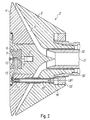
- FIG. 1 shows a rotary atomizer 1 for powder coating workpieces and one accordingly adapted bell plate according to the invention 2.
- the rotary atomizer 1 is suitable in connection with the bell plate 2 in particular for powder coating of motor vehicle body parts in series production, but also the coating other workpieces possible.
- the bell plate 2 essentially consists of an outer part 3 and an inner part coaxial to it, axially spaced from it 4, being between the outer part 3 and the inner part annular gap-shaped coating agent channel 5 that extends inside the bell plate 2 as shown over the entire
- the circumference of the bell plate 2 extends and extends axially Direction towards the free end of the bell plate 2 expanded conically.
- Those formed by the outer part 3 and the inner part 4 Boundary surfaces of the coating channel 5 run here not exactly parallel, but approach the mouth opening of the coating channel 5 towards, so that the cross section of the Coating agent channel 5 decreases towards its mouth opening, resulting in an acceleration of the coating agent flow leads in the coating agent channel 5.
- the inner part 4 of the bell plate 2 is a central part in the middle 6 used that on the right in the drawing Side blends seamlessly into the inner part and has a tip, which face the rotary atomizer 1 Side of the bell plate 2 tapers conically.
- a cup-shaped cylindrical Well in which an insert body 7 is inserted, wherein the insert body 7 has an axially continuous bore, through which a centrally arranged electrode needle 8 a High-voltage electrode 9 protrudes axially outwards.
- the High voltage electrode 9 stands during the coating operation under high voltage and serves to electrically charge the from the bell plate 2 dispensed powder-air mixture and for ionization of the air space between the rotary atomizer 1 and the workpiece to be coated.
- the mechanical connection of the inner part 3 to the outer part 4 is done by several axially extending hollow connecting bolts 10, which is distributed over the circumference of the bell plate 2 uniform angular distances are arranged.
- the fixing bolt 10 is fixed in the inner part here by a fastening screw 11, the head of which is in supports the inner part 4, the fastening screw 11 Has external thread, which in the assembled state in an internal thread engages in the hollow connecting pin 10.
- the bell plate 2 is a rinse Electrode needle 8 with purge air
- the purge air flow Electrode needle 8 flows axially and jacket-shaped, as from the Drawing can be seen.
- the purge air is supplied successfully here in the bell plate 2 through a purge air channel, wherein the purge air channel starting from the electrode needle 8 initially by a radially extending one arranged in the insert body 7 Stitch bore 12 is formed, which in the middle part 6 in a corresponding connection bore 13 passes over.
- the Detergent channel in the bell plate 2 then through a hole formed axially through the mounting screw 11 goes and the inside of the hollow connecting bolt 10 with the connection hole 13 connects, so that the inside of the connecting bolt 10 forms part of the detergent channel.
- the supply of the detergent to the detergent channel of the Bell plate 2 takes place here by the rotary atomizer 1, which also has a detergent channel for this purpose a housing 14 of the rotary atomizer 1, wherein the Detergent channel of the rotary atomizer 1 through several lines 15 - 18 is formed, which finally in an annular channel 19th open, which has an annular circumferential outlet opening, the outlet opening of the ring channel 19 at the free Front side of the rotary atomizer 1 is and when mounted Bell plate 2 with a small gap in front of the mouth opening of the hollow connecting pin 10, so that independently always purging air from the rotary position of the bell plate 2 enter the ring channel 19 into the flushing channel of the bell cup 2 can.
- the rotary atomizer 1 has a rotatably mounted one Bell plate shaft 20, which has an internal thread at its free end wearing.
- the outer part 3 of the bell plate 2 has a correspondingly adapted Male thread on, so that the bell plate 2 in the assembled Condition is screwed onto the bell cup shaft 20.
- the rotary atomizer 1 has a coating agent channel 21 on the inside of a centrally located Powder tube 22 is formed.
- the coating agent channel is in the rotary atomizer 1 according to the invention 21 So from the detergent channel 15-19 separated, with the outlet openings of the coating agent channel 21 and the detergent channel 15 - 19 separated from each other are an independent supply of detergent and To enable coating agents.
- the coating agent channel 5 is also in the Bell plate 2 from the detergent channel 12, 13 in the bell plate 2 separated so that the flushing of the electrode needle 8 can take place during the actual coating operation.
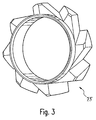
- a special feature of the bell plate 2 ' is that the , Supply of the purge air to the bell plate 2 'not through the 1 is also shown in FIG. 1, but by a turbine 23 ', which is detailed in FIG 3 is shown and rotates with the bell plate 2 '. While of the coating company with the bell plate rotating 2 'sucks the turbine 23' in ambient air and conveys it into the inside of the connecting bolt 10 'and thus into the detergent channel of the bell plate 2 '.
- a special feature of the bell plate 2 '' is first of all that in the middle part 6 "of the inner part 4" of Bell plate 2 '' no electrode needle is located.
- the bell plate 2 '' it is within the scope of the invention also possible with the bell plate 2 '' to provide an electrode needle, as is the case with the bell cup 2 is the case in Figure 1.
- Another special feature of the bell plate 2 ′′ is that the connecting bolts 10 ′′ between the inner part 4 ′′ and the outer part 3 ′′ of the bell plate 2 ′′ are protected against buildup of coating agents.
- outlet openings 24 ′′ are arranged in the wall of the connecting bolt 10 ′′, through which flushing agent can escape from the connecting bolt 10 ′′ to the outside into the coating agent channel 5 ′′, thereby preventing coating agent from adhering to the connecting bolt 10 ′′.
- the outlet openings 24 ′′ are in this case made on the inside and outside with respect to the axis of rotation of the bell plate 2 ′′, so that there is protection on the entire circumferential surface of the connecting bolts 10 ′′ against buildup of coating agents.
- the connecting bolts 10 '' are made of a plastic sleeve 25 '', which also the connecting bolts 10 '' protects against buildup of coating agents.
- the Plastic sleeves 25 '' are air-permeable, so that from the connecting bolts 10 '' through the outlet openings 24 '' detergent escaping through the plastic sleeve 25 "is not stopped.
Landscapes
- Nozzles (AREA)
- Electrostatic Spraying Apparatus (AREA)
- Vaporization, Distillation, Condensation, Sublimation, And Cold Traps (AREA)
- Agricultural Chemicals And Associated Chemicals (AREA)
- Application Of Or Painting With Fluid Materials (AREA)
Abstract
Description
- Figur 1
- eine Querschnittsansicht eines erfindungsgemäßen Rotationszerstäubers mit einem erfindungsgemäßen Glockenteller,
- Figur 2
- ein alternatives Ausführungsbeispiel eines erfindungsgemäßen Glockentellers mit einer Turbine zur Förderung von Spülmittel,
- Figur 3
- die Turbine des Glockentellers aus Figur 2 in einer perspektivischen Darstellung,
- Figur 4
- ein weiteres alternatives Ausführungsbeispiel eines erfindungsgemäßen Glockentellers sowie
- Figur 5
- einen vergrößerten Ausschnitt "X" des Glockentellers aus Figur 4 im Bereich eines Verbindungsbolzens.
Hierzu sind in der Wandung des Verbindungsbolzens 10'' Austrittsöffnungen 24'' angeordnet, durch die Spülmittel aus den Verbindungsbolzen 10'' nach außen in den Beschichtungsmittelkanal 5" austreten kann, wodurch Anhaftungen von Beschichtungsmittel an den Verbindungsbolzen 10" verhindert wird. Die Austrittsöffnungen 24'' sind hierbei bezüglich der Rotationsachse des Glockentellers 2'' innen und außen angebracht, so dass an der gesamten Umfangsfläche der Verbindungsbolzen 10'' ein Schutz vor Anhaftungen von Beschichtungsmitteln besteht.
Claims (16)
- Glockenteller (2, 2', 2") für einen Rotationszerstäuber (1) zur Beschichtung von Werkstücken, insbesondere zur Pulverbeschichtung, mit einem Beschichtungsmittelkanal (5, 5', 5") zur Zuführung eines Beschichtungsmittels für die Beschichtung der Werkstücke, dadurch gekennzeichnet, dass zur Zuführung eines Spülmittels zur Reinigung des Glockentellers (2, 2', 2") von anhaftenden Beschichtungsmittelresten ein Spülmittelkanal (12, 12', 13, 13') vorgesehen ist, wobei der Spülmittelkanal (12, 12', 13, 13') von dem Beschichtungsmittelkanal (5, 5', 5") getrennt ist, um eine Verunreinigung des Spülmittels durch das Beschichtungsmittel zu verhindern und während des Beschichtungsbetriebs eine Spülung zu ermöglichen.
- Glockenteller (2, 2') nach Anspruch 1, dadurch gekennzeichnet, dass zur elektrischen Aufladung des abgegebenen Beschichtungsmittels eine Hochspannungselektrode (9, 9') vorgesehen ist und der Spülmittelkanal (12, 12', 13, 13') eine Austrittsöffnung aufweist, die auf die Hochspannungselektrode (9, 9') gerichtet ist, um während des Beschichtungsbetriebs eine Verunreinigung der Hochspannungselektrode (9, 9') zu verhindern.
- Glockenteller (2, 2', 2") nach Anspruch 2, dadurch gekennzeichnet, dass die Hochspannungselektrode (9, 9') eine Elektrodennadel (8, 8') aufweist, wobei der Spülmittelstrom im wesentlichen mantelförmig und koaxial zu der Elektrodennadel (8, 8') verläuft.
- Glockenteller (2, 2', 2") nach mindestens einem der vorhergehenden Ansprüche, dadurch gekennzeichnet, dass der Beschichtungsmittelkanal (5, 5', 5") zwischen einem Innenteil (4, 4', 4") und einem Außenteil (3, 3', 3") verläuft, wobei das Innenteil (4, 4', 4") durch mindestens einen hohlen Verbindungsbolzen (10, 10', 10") mit dem Außenteil (3, 3', 3") verbunden ist, während der Spülmittelkanal durch den Verbindungsbolzen (10, 10', 10") hindurch verläuft.
- Glockenteller (2, 2') nach Anspruch 4, dadurch gekennzeichnet, dass zur Fixierung des Verbindungsbolzens (10, 10') in dem Innenteil (4, 4') eine Befestigungsschraube (11, 11') vorgesehen ist, wobei die Befestigungsschraube (11, 11') eine axial durchgehende Bohrung zur Durchleitung des Spülmittels aufweist.
- Glockenteller (2") nach Anspruch 4 oder 5, dadurch gekennzeichnet, dass der in dem Verbindungsbolzen (10") verlaufende Spülmittelkanal mindestens eine Austrittsöffnung (24") aufweist, die in den Beschichtungsmittelkanal (5") mündet.
- Glockenteller nach Anspruch 6, dadurch gekennzeichnet, dass der Verbindungsbolzen (10") zumindest im Bereich des Beschichtungsmittelkanals (5") von einer Kunststoffhülse (25") umgeben ist, wobei die Kunststoffhülse (25") mindestens teilweise luftdurchlässig ist.
- Glockenteller (2, 2', 2") nach mindestens einem der vorhergehenden Ansprüche, dadurch gekennzeichnet, dass der Spülmittelkanal (12, 12', 13, 13') mit dem Glockenteller (2, 2', 2") umläuft.
- Glockenteller (2, 2', 2") nach mindestens einem der vorhergehenden Ansprüche, dadurch gekennzeichnet, dass zur Zuführung des Spülmittels eine mit dem Glockenteller (2, 2', 2") umlaufende Turbine (23') vorgesehen ist, die Umgebungsluft ansaugt und als Spülmittel in den Spülmittelkanal (12', 13') fördert.
- Glockenteller (2, 2', 2") nach mindestens einem der vorhergehenden Ansprüche, dadurch gekennzeichnet, dass der Spülmittelkanal zur Zuführung des Spülmittels von dem Rotationszerstäuber (1) eine Eintrittsöffnung aufweist, deren Querschnittsfläche rechtwinklig zu der Drehachse des Glockentellers (2, 2', 2") verläuft.
- Rotationszerstäuber (1) zur Beschichtung von Werkstücken, insbesondere zur Pulverbeschichtung, mit einer drehbar gelagerten Glockentellerwelle (20, 20') zum Antrieb eines Glockentellers (2, 2', 2"), einem Beschichtungsmittelkanal (21, 21') zur Zuführung eines Beschichtungsmittels zu dem Glockenteller (2, 2', 2") und einem Spülmittelkanal (15-19) zur Zuführung eines Spülmittels zur Reinigung des Glockentellers (2, 2', 2"), dadurch gekennzeichnet, dass der Spülmittelkanal (15-19) und der Beschichtungsmittelkanal (21) zu dem Glockenteller (2, 2', 2") hin voneinander getrennte Austrittsöffnungen aufweisen, um eine getrennte Zuführung des Beschichtungsmittels und des Spülmittels zu dem Glockenteller (2, 2', 2") zu ermöglichen.
- Rotationszerstäuber (1) nach Anspruch 11, dadurch gekennzeichnet, dass der Spülmittelkanal (15-18) in einen Ringkanal (19) mündet, der zu der Glockentellerwelle koaxial angeordnet ist und eine bezüglich der Glockentellerwelle ringförmig umlaufende Austrittsöffnung aufweist.
- Rotationszerstäuber (1) nach Anspruch 11 oder 12, dadurch gekennzeichnet, dass die Austrittsöffnung des Spülmittelkanals (15-19) eine rechtwinklig zu der Glockentellerwelle (20, 20') verlaufende Querschnittsfläche aufweist.
- Rotationszerstäuber (1) nach mindestens einem der Ansprüche 11 bis 13, dadurch gekennzeichnet, dass der Spülmittelkanal (15-19) feststehend ist.
- Rotationszerstäuber (1) nach mindestens einem der Ansprüche 11 bis 14, dadurch gekennzeichnet, dass auf der Glockentellerwelle (20, 20') ein Glockenteller (2, 2', 2") nach mindestens einem der Ansprüche 1 bis 10 angebracht ist.
- Rotationszerstäuber (1) nach Anspruch 15, dadurch gekennzeichnet, dass am Übergang zu dem Spülmittelkanal des Glockentellers (2, 2', 2") eine dynamische Dichtung vorgesehen ist.
Applications Claiming Priority (4)
| Application Number | Priority Date | Filing Date | Title |
|---|---|---|---|
| DE20314234U | 2003-02-27 | ||
| DE20314234 | 2003-02-27 | ||
| DE10342188 | 2003-09-12 | ||
| DE10342188A DE10342188A1 (de) | 2003-02-27 | 2003-09-12 | Glockenteller und Rotationszerstäuber |
Publications (3)
| Publication Number | Publication Date |
|---|---|
| EP1452235A2 true EP1452235A2 (de) | 2004-09-01 |
| EP1452235A3 EP1452235A3 (de) | 2006-04-19 |
| EP1452235B1 EP1452235B1 (de) | 2009-01-14 |
Family
ID=32773185
Family Applications (1)
| Application Number | Title | Priority Date | Filing Date |
|---|---|---|---|
| EP04003653A Expired - Lifetime EP1452235B1 (de) | 2003-02-27 | 2004-02-18 | Glockenteller und Rotationszerstäuber |
Country Status (4)
| Country | Link |
|---|---|
| EP (1) | EP1452235B1 (de) |
| AT (1) | ATE420730T1 (de) |
| DE (2) | DE10342188A1 (de) |
| ES (1) | ES2320879T3 (de) |
Families Citing this family (1)
| Publication number | Priority date | Publication date | Assignee | Title |
|---|---|---|---|---|
| DE102009018294B4 (de) * | 2009-04-21 | 2018-08-09 | Bayerische Motoren Werke Aktiengesellschaft | Mischvorrichtung |
Family Cites Families (15)
| Publication number | Priority date | Publication date | Assignee | Title |
|---|---|---|---|---|
| US4896834A (en) * | 1984-08-30 | 1990-01-30 | The Devilbiss Company | Rotary atomizer apparatus |
| US4887770A (en) * | 1986-04-18 | 1989-12-19 | Nordson Corporation | Electrostatic rotary atomizing liquid spray coating apparatus |
| GB2190606B (en) * | 1986-05-19 | 1990-02-14 | Graco Inc | A rotary spray atomizer |
| ES2004334B3 (es) * | 1987-03-23 | 1992-01-16 | Behr Ind Gmbh & Co | Procedimiento para el recubrimiento electrostatico de pieza de trabajo |
| DE3720200A1 (de) * | 1987-06-16 | 1988-12-29 | Ransburg Gmbh | Spruehbeschichtungseinrichtung mit einem rotationsspruehorgan |
| DE3912700C1 (en) * | 1989-04-18 | 1990-10-11 | Ransburg-Gema Gmbh, 6056 Heusenstamm, De | Rotary spray coater - has atomiser ring with solvent channels, and includes annular air inlets |
| FR2652518B1 (fr) * | 1989-10-03 | 1994-04-08 | Sames Sa | Dispositif de projection de produit de revetement a organe rotatif de pulverisation. |
| FR2661115B1 (fr) * | 1990-04-24 | 1992-07-31 | Sames Sa | Dispositif de pulverisation centrifuge d'un produit de revetement, notamment pour application par projection electrostatique. |
| CA2061069C (en) * | 1991-02-27 | 1999-06-29 | Toshio Kubota | Method of electrostatically spray-coating a workpiece with paint |
| DE19506968A1 (de) * | 1995-02-13 | 1996-08-14 | Ind Lackieranlagen Schmidt Gmb | Hochrotationszerstäuber |
| US6105886A (en) * | 1995-05-19 | 2000-08-22 | Nordson Corporation | Powder spray gun with rotary distributor |
| DE19542863A1 (de) * | 1995-11-17 | 1997-05-22 | Abb Research Ltd | Pulversprüheinrichtung |
| US6578779B2 (en) * | 2000-10-18 | 2003-06-17 | Behr Systems, Inc. | Rotary atomizer with bell element |
| US6341734B1 (en) * | 2000-10-19 | 2002-01-29 | Efc Systems, Inc. | Rotary atomizer and bell cup and methods thereof |
| US6569258B2 (en) * | 2001-05-16 | 2003-05-27 | Fanuc Robotics North America, Inc. | Method and apparatus for cleaning a bell atomizer spray head |
-
2003
- 2003-09-12 DE DE10342188A patent/DE10342188A1/de not_active Ceased
-
2004
- 2004-02-18 DE DE502004008850T patent/DE502004008850D1/de not_active Expired - Lifetime
- 2004-02-18 ES ES04003653T patent/ES2320879T3/es not_active Expired - Lifetime
- 2004-02-18 EP EP04003653A patent/EP1452235B1/de not_active Expired - Lifetime
- 2004-02-18 AT AT04003653T patent/ATE420730T1/de not_active IP Right Cessation
Also Published As
| Publication number | Publication date |
|---|---|
| ES2320879T3 (es) | 2009-05-29 |
| DE502004008850D1 (de) | 2009-03-05 |
| EP1452235B1 (de) | 2009-01-14 |
| ATE420730T1 (de) | 2009-01-15 |
| DE10342188A1 (de) | 2004-09-16 |
| EP1452235A3 (de) | 2006-04-19 |
Similar Documents
| Publication | Publication Date | Title |
|---|---|---|
| EP0715896B1 (de) | Rotationszerstäuber mit einem Glockenkörper | |
| EP2643096B1 (de) | Reinigungsgerät und reinigungsbürste für einen zerstäuber und entsprechendes reinigungsverfahren | |
| EP2099570B1 (de) | Lenkluftring mit einer ringmulde und entsprechender glockenteller | |
| DE69717416T2 (de) | Rotationszerstäubungskopf | |
| EP0294606B1 (de) | Einrichtung zum Vernebeln flüssiger Farbe | |
| DE3912700C1 (en) | Rotary spray coater - has atomiser ring with solvent channels, and includes annular air inlets | |
| EP2485848B1 (de) | Düsenanordnung | |
| EP1634651B1 (de) | Verfahren, Beschichtungsanlage und Rotationszerstäuber zur Serienbeschichtung von Werkstücken | |
| DE112020006287T5 (de) | Mischvorrichtung für beschichtungsflüssigkeiten und verfahren zum mischen von beschichtungsflüssigkeiten | |
| DE60224152T2 (de) | Verfahren und Vorrichtung zur Reduzierung von Farbablagerungen auf der Zufuhrleitung eines Rotationszerstäubers | |
| DE102010011064A1 (de) | Ventileinheit für eine Beschichtungsanlage | |
| EP3887057B1 (de) | Rotationszerstäuber | |
| EP2620226B1 (de) | Behälterreinigungsvorrichtung | |
| DE3151929A1 (de) | Vorrichtung zum aufeinanderfolgenden auftragen verschiedener ueberzugsfluessigkeiten | |
| DE102010030761B4 (de) | Strahlfangdüse für einen Pulverförderinjektor sowie Pulverförderinjektor | |
| EP1452235B1 (de) | Glockenteller und Rotationszerstäuber | |
| DE19506968A1 (de) | Hochrotationszerstäuber | |
| EP1367302A2 (de) | Dichtungsanordnung | |
| DE3720200A1 (de) | Spruehbeschichtungseinrichtung mit einem rotationsspruehorgan | |
| DE202005021573U1 (de) | Behälterreinigungsvorrichtung | |
| EP0827781B1 (de) | Rotationszerstäuber | |
| DE10308630A1 (de) | Glockenteller und Rotationszerstäuber | |
| DE3816417C2 (de) | ||
| EP4377016A1 (de) | Glockenteller, rotationszerstäuber mit dem glockenteller, lackieranlage und entsprechendes lackierverfahren | |
| EP1481733B1 (de) | Glockenteller für Rotationzerstäuber |
Legal Events
| Date | Code | Title | Description |
|---|---|---|---|
| PUAI | Public reference made under article 153(3) epc to a published international application that has entered the european phase |
Free format text: ORIGINAL CODE: 0009012 |
|
| AK | Designated contracting states |
Kind code of ref document: A2 Designated state(s): AT BE BG CH CY CZ DE DK EE ES FI FR GB GR HU IE IT LI LU MC NL PT RO SE SI SK TR |
|
| AX | Request for extension of the european patent |
Extension state: AL LT LV MK |
|
| PUAL | Search report despatched |
Free format text: ORIGINAL CODE: 0009013 |
|
| AK | Designated contracting states |
Kind code of ref document: A3 Designated state(s): AT BE BG CH CY CZ DE DK EE ES FI FR GB GR HU IE IT LI LU MC NL PT RO SE SI SK TR |
|
| AX | Request for extension of the european patent |
Extension state: AL LT LV MK |
|
| 17P | Request for examination filed |
Effective date: 20060424 |
|
| AKX | Designation fees paid |
Designated state(s): AT BE BG CH CY CZ DE DK EE ES FI FR GB GR HU IE IT LI LU MC NL PT RO SE SI SK TR |
|
| 17Q | First examination report despatched |
Effective date: 20070411 |
|
| REG | Reference to a national code |
Ref country code: SE Ref legal event code: TRGR |
|
| GRAP | Despatch of communication of intention to grant a patent |
Free format text: ORIGINAL CODE: EPIDOSNIGR1 |
|
| GRAS | Grant fee paid |
Free format text: ORIGINAL CODE: EPIDOSNIGR3 |
|
| GRAA | (expected) grant |
Free format text: ORIGINAL CODE: 0009210 |
|
| AK | Designated contracting states |
Kind code of ref document: B1 Designated state(s): AT BE BG CH CY CZ DE DK EE ES FI FR GB GR HU IE IT LI LU MC NL PT RO SE SI SK TR |
|
| REG | Reference to a national code |
Ref country code: GB Ref legal event code: FG4D Free format text: NOT ENGLISH |
|
| REG | Reference to a national code |
Ref country code: CH Ref legal event code: EP |
|
| REG | Reference to a national code |
Ref country code: IE Ref legal event code: FG4D Free format text: LANGUAGE OF EP DOCUMENT: GERMAN |
|
| REF | Corresponds to: |
Ref document number: 502004008850 Country of ref document: DE Date of ref document: 20090305 Kind code of ref document: P |
|
| REG | Reference to a national code |
Ref country code: DE Ref legal event code: R096 Ref document number: 502004008850 Country of ref document: DE Effective date: 20090305 |
|
| REG | Reference to a national code |
Ref country code: ES Ref legal event code: FG2A Ref document number: 2320879 Country of ref document: ES Kind code of ref document: T3 |
|
| PG25 | Lapsed in a contracting state [announced via postgrant information from national office to epo] |
Ref country code: FI Free format text: LAPSE BECAUSE OF FAILURE TO SUBMIT A TRANSLATION OF THE DESCRIPTION OR TO PAY THE FEE WITHIN THE PRESCRIBED TIME-LIMIT Effective date: 20090114 Ref country code: SI Free format text: LAPSE BECAUSE OF FAILURE TO SUBMIT A TRANSLATION OF THE DESCRIPTION OR TO PAY THE FEE WITHIN THE PRESCRIBED TIME-LIMIT Effective date: 20090114 |
|
| REG | Reference to a national code |
Ref country code: IE Ref legal event code: FD4D |
|
| PG25 | Lapsed in a contracting state [announced via postgrant information from national office to epo] |
Ref country code: PT Free format text: LAPSE BECAUSE OF FAILURE TO SUBMIT A TRANSLATION OF THE DESCRIPTION OR TO PAY THE FEE WITHIN THE PRESCRIBED TIME-LIMIT Effective date: 20090615 |
|
| PG25 | Lapsed in a contracting state [announced via postgrant information from national office to epo] |
Ref country code: MC Free format text: LAPSE BECAUSE OF NON-PAYMENT OF DUE FEES Effective date: 20090228 |
|
| REG | Reference to a national code |
Ref country code: CH Ref legal event code: PL |
|
| PG25 | Lapsed in a contracting state [announced via postgrant information from national office to epo] |
Ref country code: IE Free format text: LAPSE BECAUSE OF FAILURE TO SUBMIT A TRANSLATION OF THE DESCRIPTION OR TO PAY THE FEE WITHIN THE PRESCRIBED TIME-LIMIT Effective date: 20090114 Ref country code: EE Free format text: LAPSE BECAUSE OF FAILURE TO SUBMIT A TRANSLATION OF THE DESCRIPTION OR TO PAY THE FEE WITHIN THE PRESCRIBED TIME-LIMIT Effective date: 20090114 Ref country code: LI Free format text: LAPSE BECAUSE OF NON-PAYMENT OF DUE FEES Effective date: 20090228 Ref country code: CZ Free format text: LAPSE BECAUSE OF FAILURE TO SUBMIT A TRANSLATION OF THE DESCRIPTION OR TO PAY THE FEE WITHIN THE PRESCRIBED TIME-LIMIT Effective date: 20090114 Ref country code: DK Free format text: LAPSE BECAUSE OF FAILURE TO SUBMIT A TRANSLATION OF THE DESCRIPTION OR TO PAY THE FEE WITHIN THE PRESCRIBED TIME-LIMIT Effective date: 20090114 Ref country code: CH Free format text: LAPSE BECAUSE OF NON-PAYMENT OF DUE FEES Effective date: 20090228 |
|
| PLBE | No opposition filed within time limit |
Free format text: ORIGINAL CODE: 0009261 |
|
| STAA | Information on the status of an ep patent application or granted ep patent |
Free format text: STATUS: NO OPPOSITION FILED WITHIN TIME LIMIT |
|
| PG25 | Lapsed in a contracting state [announced via postgrant information from national office to epo] |
Ref country code: RO Free format text: LAPSE BECAUSE OF FAILURE TO SUBMIT A TRANSLATION OF THE DESCRIPTION OR TO PAY THE FEE WITHIN THE PRESCRIBED TIME-LIMIT Effective date: 20090114 Ref country code: SK Free format text: LAPSE BECAUSE OF FAILURE TO SUBMIT A TRANSLATION OF THE DESCRIPTION OR TO PAY THE FEE WITHIN THE PRESCRIBED TIME-LIMIT Effective date: 20090114 |
|
| 26N | No opposition filed |
Effective date: 20091015 |
|
| PG25 | Lapsed in a contracting state [announced via postgrant information from national office to epo] |
Ref country code: BG Free format text: LAPSE BECAUSE OF FAILURE TO SUBMIT A TRANSLATION OF THE DESCRIPTION OR TO PAY THE FEE WITHIN THE PRESCRIBED TIME-LIMIT Effective date: 20090414 |
|
| REG | Reference to a national code |
Ref country code: DE Ref legal event code: R097 Ref document number: 502004008850 Country of ref document: DE Effective date: 20091015 |
|
| REG | Reference to a national code |
Ref country code: DE Ref legal event code: R081 Ref document number: 502004008850 Country of ref document: DE Owner name: DUERR SYSTEMS AG, DE Free format text: FORMER OWNER: DUERR SYSTEMS GMBH, 70435 STUTTGART, DE Effective date: 20100115 |
|
| PG25 | Lapsed in a contracting state [announced via postgrant information from national office to epo] |
Ref country code: AT Free format text: LAPSE BECAUSE OF NON-PAYMENT OF DUE FEES Effective date: 20090218 |
|
| PG25 | Lapsed in a contracting state [announced via postgrant information from national office to epo] |
Ref country code: GR Free format text: LAPSE BECAUSE OF FAILURE TO SUBMIT A TRANSLATION OF THE DESCRIPTION OR TO PAY THE FEE WITHIN THE PRESCRIBED TIME-LIMIT Effective date: 20090415 |
|
| PG25 | Lapsed in a contracting state [announced via postgrant information from national office to epo] |
Ref country code: LU Free format text: LAPSE BECAUSE OF NON-PAYMENT OF DUE FEES Effective date: 20090218 |
|
| PG25 | Lapsed in a contracting state [announced via postgrant information from national office to epo] |
Ref country code: HU Free format text: LAPSE BECAUSE OF FAILURE TO SUBMIT A TRANSLATION OF THE DESCRIPTION OR TO PAY THE FEE WITHIN THE PRESCRIBED TIME-LIMIT Effective date: 20090715 |
|
| PG25 | Lapsed in a contracting state [announced via postgrant information from national office to epo] |
Ref country code: TR Free format text: LAPSE BECAUSE OF FAILURE TO SUBMIT A TRANSLATION OF THE DESCRIPTION OR TO PAY THE FEE WITHIN THE PRESCRIBED TIME-LIMIT Effective date: 20090114 |
|
| PG25 | Lapsed in a contracting state [announced via postgrant information from national office to epo] |
Ref country code: CY Free format text: LAPSE BECAUSE OF FAILURE TO SUBMIT A TRANSLATION OF THE DESCRIPTION OR TO PAY THE FEE WITHIN THE PRESCRIBED TIME-LIMIT Effective date: 20090114 |
|
| REG | Reference to a national code |
Ref country code: FR Ref legal event code: PLFP Year of fee payment: 12 |
|
| PGFP | Annual fee paid to national office [announced via postgrant information from national office to epo] |
Ref country code: NL Payment date: 20150218 Year of fee payment: 12 |
|
| PGFP | Annual fee paid to national office [announced via postgrant information from national office to epo] |
Ref country code: IT Payment date: 20150226 Year of fee payment: 12 Ref country code: ES Payment date: 20150225 Year of fee payment: 12 Ref country code: DE Payment date: 20150219 Year of fee payment: 12 |
|
| PGFP | Annual fee paid to national office [announced via postgrant information from national office to epo] |
Ref country code: SE Payment date: 20150218 Year of fee payment: 12 Ref country code: FR Payment date: 20150219 Year of fee payment: 12 Ref country code: GB Payment date: 20150218 Year of fee payment: 12 |
|
| PGFP | Annual fee paid to national office [announced via postgrant information from national office to epo] |
Ref country code: BE Payment date: 20150218 Year of fee payment: 12 |
|
| PG25 | Lapsed in a contracting state [announced via postgrant information from national office to epo] |
Ref country code: BE Free format text: LAPSE BECAUSE OF NON-PAYMENT OF DUE FEES Effective date: 20160229 |
|
| REG | Reference to a national code |
Ref country code: DE Ref legal event code: R119 Ref document number: 502004008850 Country of ref document: DE |
|
| REG | Reference to a national code |
Ref country code: DE Ref legal event code: R082 Ref document number: 502004008850 Country of ref document: DE Representative=s name: V. BEZOLD & PARTNER PATENTANWAELTE - PARTG MBB, DE Ref country code: DE Ref legal event code: R081 Ref document number: 502004008850 Country of ref document: DE Owner name: DUERR SYSTEMS AG, DE Free format text: FORMER OWNER: DUERR SYSTEMS GMBH, 74321 BIETIGHEIM-BISSINGEN, DE |
|
| REG | Reference to a national code |
Ref country code: SE Ref legal event code: EUG |
|
| GBPC | Gb: european patent ceased through non-payment of renewal fee |
Effective date: 20160218 |
|
| REG | Reference to a national code |
Ref country code: NL Ref legal event code: MM Effective date: 20160301 |
|
| REG | Reference to a national code |
Ref country code: FR Ref legal event code: ST Effective date: 20161028 |
|
| PG25 | Lapsed in a contracting state [announced via postgrant information from national office to epo] |
Ref country code: SE Free format text: LAPSE BECAUSE OF NON-PAYMENT OF DUE FEES Effective date: 20160219 |
|
| PG25 | Lapsed in a contracting state [announced via postgrant information from national office to epo] |
Ref country code: IT Free format text: LAPSE BECAUSE OF NON-PAYMENT OF DUE FEES Effective date: 20160218 |
|
| PG25 | Lapsed in a contracting state [announced via postgrant information from national office to epo] |
Ref country code: GB Free format text: LAPSE BECAUSE OF NON-PAYMENT OF DUE FEES Effective date: 20160218 Ref country code: FR Free format text: LAPSE BECAUSE OF NON-PAYMENT OF DUE FEES Effective date: 20160229 Ref country code: NL Free format text: LAPSE BECAUSE OF NON-PAYMENT OF DUE FEES Effective date: 20160301 Ref country code: DE Free format text: LAPSE BECAUSE OF NON-PAYMENT OF DUE FEES Effective date: 20160901 |
|
| PG25 | Lapsed in a contracting state [announced via postgrant information from national office to epo] |
Ref country code: ES Free format text: LAPSE BECAUSE OF NON-PAYMENT OF DUE FEES Effective date: 20160219 |
|
| REG | Reference to a national code |
Ref country code: ES Ref legal event code: FD2A Effective date: 20181205 |
|
| P01 | Opt-out of the competence of the unified patent court (upc) registered |
Effective date: 20230512 |