EP1452276B1 - Dispositif de support pour éléments de fixation - Google Patents
Dispositif de support pour éléments de fixation Download PDFInfo
- Publication number
- EP1452276B1 EP1452276B1 EP04100747A EP04100747A EP1452276B1 EP 1452276 B1 EP1452276 B1 EP 1452276B1 EP 04100747 A EP04100747 A EP 04100747A EP 04100747 A EP04100747 A EP 04100747A EP 1452276 B1 EP1452276 B1 EP 1452276B1
- Authority
- EP
- European Patent Office
- Prior art keywords
- holding device
- gripping
- gripping elements
- guide
- fastener
- Prior art date
- Legal status (The legal status is an assumption and is not a legal conclusion. Google has not performed a legal analysis and makes no representation as to the accuracy of the status listed.)
- Expired - Lifetime
Links
Images


Classifications
-
- B—PERFORMING OPERATIONS; TRANSPORTING
- B25—HAND TOOLS; PORTABLE POWER-DRIVEN TOOLS; MANIPULATORS
- B25B—TOOLS OR BENCH DEVICES NOT OTHERWISE PROVIDED FOR, FOR FASTENING, CONNECTING, DISENGAGING, OR HOLDING
- B25B23/00—Details of, or accessories for, spanners, wrenches, screwdrivers
- B25B23/02—Arrangements for handling screws or nuts
- B25B23/08—Arrangements for handling screws or nuts for holding or positioning screw or nut prior to or during its rotation
- B25B23/10—Arrangements for handling screws or nuts for holding or positioning screw or nut prior to or during its rotation using mechanical gripping means
-
- B—PERFORMING OPERATIONS; TRANSPORTING
- B23—MACHINE TOOLS; METAL-WORKING NOT OTHERWISE PROVIDED FOR
- B23P—METAL-WORKING NOT OTHERWISE PROVIDED FOR; COMBINED OPERATIONS; UNIVERSAL MACHINE TOOLS
- B23P19/00—Machines for simply fitting together or separating metal parts or objects, or metal and non-metal parts, whether or not involving some deformation; Tools or devices therefor so far as not provided for in other classes
- B23P19/001—Article feeders for assembling machines
- B23P19/006—Holding or positioning the article in front of the applying tool
Definitions
- the invention relates to a holding device for holding fasteners, such as screws, which can be fixed to a screwdriver and with a Swissfardes a fastening means, which can be used, for example, from a front side of the screwing ago in a tool bit, is additionally supported, wherein the holding device at least two gripping elements which can be applied in a support position on a shaft of the fastening means and which can be laid by a force application in a release position in which they are spaced from the shaft.
- fasteners such as screws
- a fastening means which can be used, for example, from a front side of the screwing ago in a tool bit
- Such holding devices allow an automatic holding of the fastening means on the screwdriver and thereby facilitate the screwing considerably.
- such holding devices are very advantageous because they support the screws radially and thereby wobble the screws and resulting damage avoid on the surfaces.
- a time-consuming predrilling can be dispensed with in many cases. Overall, the screwing process is thus simplified by the holding devices and damage to the assembly workpieces avoided.
- a screwdriver with a screw holding means which has two claws respectively arranged at the end of a pivoting arm for temporarily holding a screw.
- the pivot arms are mounted on a sleeve, which in turn is mounted on an inner further sleeve. If a screw is screwed into a workpiece with the screwdriver, then this is first held over the two claws. With progressive screwing in the screw, the inner sleeve presses with the located at its end facing the screw from the inside against the pivot arms and spreads them, the screw is released.
- DE 40 37 547 shows a device for mounting screws, which is fixed via a sleeve-shaped component to a screwdriver.
- a likewise sleeve-shaped support member is guided telescopically on the component and carries two, each rotatable about a pin gripping elements in the form of holding jaws which protrude in the rest position approximately perpendicular to the inner wall of the support member inwardly while supporting the shank of a screw with their free ends.
- the front side of the supporting part which is in the working direction, comes into contact with the workpiece into which the screw is driven.
- the support member is moved by the back pressure of the workpiece relative to the component and with respect to the screw. This is the screw head in contact with the holding jaws, which pivots out of the drive path of the screw in the direction of the workpiece.
- the holding jaws To ensure that the screw can be driven into the workpiece as far as it will go, it is necessary here for the holding jaws to be moved completely behind the end face of the tool bit in the driving direction.
- the known approach has the disadvantage that, among other things, the entire length of the holding jaws must be kept as a shift length of the support member relative to the component. As a consequence, it is necessary to connect the spindle of the screwdriver via a special extension with the tool bit or to use a specially shaped, long tool bit. This will incur additional costs.
- the present invention has for its object to provide a holding device for screws, which avoids the aforementioned disadvantages and has a simple construction of short length.
- the gripping elements come into contact with the workpiece, in which the fastener is driven.
- the force is applied to the laying of the gripping elements in the release position directly through the workpiece.
- the length of the holding device can be shortened with a simple design.
- a secure and timely actuation of the gripping elements is ensured by the direct loading of the gripping elements by the workpiece.
- the at least one contact region is formed by at least one roller.
- rollers on the one hand a low-friction radial movement of the gripping elements on the workpiece surface in relation to Eintreibachse allows, which reduces the force required in the operation of the gripping device.
- scratch marks or other damage to the workpiece can be avoided, especially if the rollers have at least on their lateral surface a soft material such as rubber or soft plastic.
- the roller is spherically shaped. This avoids that the rollers, especially in an oblique placement of the holding device on a workpiece surface, cause Eindschreibspuren by roller edges.
- the gripping elements are formed by gripping arms, which are held on the one hand via a pivot bearing, which is axially displaceable relative to a transmission part of the screwing in the driving direction.
- the storage of the gripping arms takes place via a link guide.
- Both the axial and the radial path component is performed by a uniform movement of the gripping elements, whereby the overall structure of the holding device can be greatly simplified.
- a relatively filigree structure can be achieved by the use of gripping arms, which ensures a low weight of the holding device and a good inspection of the fastener to be driven.
- the link guide has at least one curved guide recess, for example in the form of an elongated hole or a groove, on the respective gripper element.
- this guide recess protrudes a guide element which is connected immovably to the transmission part.
- the guide recess is most curved toward a first end on which the guide element is placed when the gripping elements are in the support position.
- the first end is formed by a straight end portion and this end portion is aligned in the support position of the holding device substantially parallel to the driving direction.
- the gripping elements are kept securely closed during the screwing, as long as the contact area has not yet come to the respective workpiece in plant.
- an accidental opening of the holding device for example, due to vibrations that occur during the screwing avoided.
- the guide recess has a straight section towards a second end, on which the guide element is placed, when the gripping elements are in the release position.
- lateral forces are avoided within the gripping elements, whereby a slimmer shape of the gripping elements is possible.
- the holding device has a latching device.
- the gripping elements can be locked in a predetermined locking position.
- a small additional force is required in the form of additional pressure between the contact region of the gripping elements and the workpiece. This makes it possible to predetermine an exact position of the gripping elements in the support position. In addition, the risk of accidental opening of the gripping device is reduced.
- the predetermined locking position of the latching device is adjustable. This makes it possible to adjust the position of the gripping elements in the support position to different shaft diameter of the fasteners to be driven.
- the locking device is formed by a relative to the transmission part in different positions fixable locking receiving element on which a sliding element is guided along, which carries the pivot bearing of the gripping elements and against the transmission part is axially displaceable.
- the latch receiving element has a recess. In this recess engages in the supporting position of the gripping elements a locking element which is displaceably held on the sliding element and biased in the direction of the locking receiving element.
- the gripping elements are biased in the release position.
- the gripping elements are guided josststieri in the release position and thus the contact area of the gripping elements are moved in the driving direction behind the bit end face of the tool bits as soon as the locking device is released from the support position.
- unnecessary contact between the gripping elements and the workpiece and thereby possible damage such as scratches on the workpiece is avoided.
- the bias is effected by a helical spring which sits on the detent element and is arranged between the sliding element and the gear part, or a component fixed thereto.
- the locking receiving element is additionally used as a guide for the biasing spring, whereby additional components can be saved.
- a gripping jaw is arranged on at least one gripping element in a region which can be placed against the shank of the fastening means.
- the gripping element also has a resilient region, for example in the form of an integrated leaf spring. Due to the resilient region, when the holding device is brought into the supporting position, an automatic adaptation of the gripping arms to the respective shaft diameter takes place. On a manual adjustment of the locking device can thus be dispensed with.
- the spring portion is formed so that it in conjunction with the straight end portion of an additional or own locking function in the support position takes over. In this way, if necessary, can be dispensed with the locking device.
- the jaw is releasably connected to the rest of the gripping element. This makes it possible to replace a gripping jaw, which shows signs of wear, without having to replace the entire gripping element.
- the jaw on a wedge-shaped recess ensures that each gripping element bears on the shaft of the fastener to be driven in via two contact lines, regardless of the diameter of the shank. In this way, a secure guidance of the shaft can be ensured by the gripping elements.
- a tool bit which has a clamping device.
- this clamping device egg n friction engagement between the tool bit and the head of the fastener is generated when inserting a fastener in the holding device.
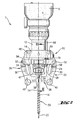
- a transmission part 4 which has a transmission housing 6.
- the transmission part 4 has an attachment end 8 (see Fig. 3 ), on which a holding device 10 is mounted via a carrier sleeve 12.
- a sliding element 14 is slidably mounted along a driving axis 16.
- two pivot bearings 18 are carried out, via which in each case a gripping arm formed as a gripping member 20 is rotatably mounted with its rear in the driving direction 22 opposite the sliding element 14 and the transmission part 4.
- each have a guide recess 24 is formed in the form of a curved elongated hole.
- the guide recess 24 is strongly curved towards a first end 26.
- the guide recess 24 has a straight section 30.
- a guide element 32 in the form of a pin.
- Both guide elements are arranged on a support member 34 which is fixedly mounted on a front in the driving direction 22 of the support sleeve 12. Both guide recesses 24 form in this way with the respective guide element 32 a slotted guide.
- both gripping elements 20 On the side facing away from the pivot bearing 18 respective end of both gripping elements 20, these each have a jaw receptacle 36 in which a gripping jaw 38 is releasably attached.
- both gripping elements 20 in the extension of the straight portion 30 of the guide recess 24 each have a roller 40 which is rotatably mounted on the respective gripping element 20.
- a spindle end 42 of the screwdriver 2 out.
- a bit holder 44 is formed, in which a tool bit 46 is used.
- a depth stop 47 is screwed into the carrier sleeve 12, which can also be removed as needed.
- the tool bit 46 again has a hexagonal receptacle 48 in the drive-in direction 22, to which a fastening means 50 in the form of a screw is inserted.
- a spring-loaded ball 52 is made on the tool bit 46, which is pressed into the hexagonal receptacle 48 through a lateral opening.
- the ball 52 presses against a hexagonal head 54 of the fastener 50, which is positioned in the inserted state of the fastener 50 in the hexagonal receptacle 48, and clamped in this way the fastener 50 to the tool bit 46.
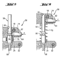
- a detent device 56 shown in more detail, having a detent receiving element 58 in the form of a pin which is clamped on the support member 34 and projects into a guide hole 60 or passes through this, which is formed on the sliding element 14.
- a receiving bore 62 Transverse to the guide bore 60, a receiving bore 62 is formed, which is open to the guide bore 60 back.
- a locking element 64 is arranged, which is biased in the direction of the guide bore 60 by a spring force F shown only schematically.
- Fig. 5 shows the latching device 56 in a latching position, which corresponds to the supporting position of the gripping elements 20.
- the latching element 64 protrudes into a recess 66 in the form of a constriction, which is formed on the latch receiving element 58.
- the sliding element 14 is held with respect to the support member 34 at a predetermined distance.
- a set screw 68 is provided on the support member 34 facing the end of the locking receiving element 58.
- a set screw 68 is provided on the support member 34 facing the end of the locking receiving element 58.
- a coil spring 70 is guided on the latch receiving element 58, which pushes the sliding element 14 away from the support element 34.
- the release position ( Fig. 6 ) occupies, in which the gripping elements 20 are opened.
- a fastener 50 with its hexagonal head 54 can be freely inserted from the front of the screwdriver 2 in the tool bit 46.
- the spring-loaded ball 52 prevents unwanted falling out of the fastener 50 from the tool bit 46th
- the operator therefore has both hands free, on the one hand to hold the screwdriver 2 and on the other hand push the sliding element 14 against the spring force of the coil spring 70 in the direction of the support member 34 until the locking element 64 as in Fig. 5 shown engages in the recess 66.
- the holding device 10 now takes in the Fig. 2 and 4 shown support position in which the coil spring 70 is biased.
- the jaws 38 of the gripping elements 20 are below the hexagonal head 54 and a sealing washer 72 on a shaft 74 of the fastener 50 at.
- the gripping jaws 38 are prism-shaped with a triangular in cross-section recess 39 and are characterized in each case via two lines of contact on the shaft 74 at.
- the distance between the two jaws 38 in the support position on the adjusting screw 68 of the latching device 56 can be accurately adjusted .
- the operator sets the distance between the sliding element 14 and the support element 34 and thus also the contact point of the guide element 32 on the guide recess 24 in the support position via the adjusting screw 68.
- the distance between the gripping jaws 38 is determined, which serves as a guide region for the shaft 74 in the support position. The operator will usually choose this distance so that the gripping jaws 38 rest in the support position just without play on the shaft 74.
- gripping jaws 38 are also possible optionally to use gripping jaws 38 with different shapes. For example, instead of the illustrated gripping jaws 38 with a triangular recess, gripping jaws with a round recess could also be selected in order to achieve improved guidance of the shaft 74.
- the screwdriver 2 is turned on and driven the fastener 50 in driving direction 22 in the workpiece, not shown.
- the gripping elements 20 support the shaft 74 in the radial direction and thus ensure safe guidance even with a large length of the fastening means 50.
- the fastening means 50 can therefore be driven without pre-drilling tumble-free in the workpiece.
- the strongly curved part of the guide recesses 24 of the gripper elements 20 is moved along the guide element 32.
- This ensures simultaneously with the axial movement of the gripping elements 20 along the driving axis 16 for a rapid pivoting of the gripping elements 20 about the respective pivot bearing 18 and thus for a pronounced radial spacing of the gripping jaws 38 from each other.
- these are displaced along the straight section 30 substantially parallel to the drive-in axis 16 and thus by the shortest path to the rear.
- the distance between the jaws 38 is already so large that they can be moved against the driving direction 22 on the sealing disc 72 and placed next to the depth stop 47 and the tool bit 46.
- the frictional engagement between the spring-loaded ball 52 and the hexagonal head 54 of the fastening means 50 is overcome by slight pulling on the screwdriver 2 against the driving-in direction 22 and the screwdriver 2 is separated from the fastening means 50.
- the coil spring 70 holds the holding device 10 in the release position according to Fig. 1 ,
- a new fastener 50 can be inserted from the considered in relation to the driving direction 22 front of the screwdriver 2 with the hexagon head 54 in the tool bit 46.
- the gripping jaws 38 for guiding the new fastening means 50 can then be applied to its shaft 74 as described above.
- Fig. 7 shows an alternative embodiment of the holding device 10, in which the gripping elements 20 have a spring portion 80, over which the jaws 38 and the jaw seats 36 relative to the remaining part of the gripping elements 20, on which the guide recess 24 is formed, in the radial direction to the driving axis 16 resilient are held.
- the spring portion 80 is formed as an integrated leaf spring in the designed as an injection molded part gripping elements 20.
- rollers 40 and the support member 34 are shown only partially.
- the guide recess 24 is applied in the end portion 82 to the guide member 32.
- the gripping jaws 38 as soon as they have come into contact with the shank 74, depending on the diameter of the shank 74, are pivoted differently with respect to the remaining gripping element 20.
- the holding device 10 is independently on the respective diameter of the shaft 74 when moving into the support position.
- the spring-loaded gripping jaws 38 compensate for radial movements of the shaft 74, which may occur as a result of eccentricities, for example on the fastener tip or along the shaft 74.
- the arrangement of the guide element 32 in the axially aligned end portion 82 also ensures that the gripping elements 20 are not accidentally released from the support position. The fastening means 50 is thus always guided safely during the screwing.
- the gripping elements 20 can be easily moved from the release position into the support position. The relocation of the gripping elements 20 back into the release position is then no longer automatically, but by pressing the rollers 40 against the workpiece during the screwing. As a result, the rollers 40 also remain in loose contact with the workpiece during the entire screwing process.
Landscapes
- Engineering & Computer Science (AREA)
- Mechanical Engineering (AREA)
- Details Of Spanners, Wrenches, And Screw Drivers And Accessories (AREA)
- Manipulator (AREA)
- Jigs For Machine Tools (AREA)
Claims (18)
- Dispositif de retenue (10) pour un élément de fixation (50) qui peut être immobilisé sur un appareil de vissage (2) et qui permet de supporter un élément de fixation (50) pouvant être inséré dans un embout d'outil (46), le dispositif de retenue (10) comportant au moins deux éléments de saisie (20) qui, dans une position de support, peuvent porter sur une tige (74) de l'élément de fixation (50) et qui, par l'application d'une force, peuvent être amenés dans une position de libération dans laquelle ils sont à distance de la tige (74), caractérisé en ce que les éléments de saisie (20) comportent au moins une zone de contact qui forme pour une pièce, au moins dans la position de support, la butée la plus en avant du dispositif de retenue (10) dans une direction d'enfoncement (22) de l'appareil de vissage (2), dans lequel, dans la position de libération, une force peut être appliquée aux éléments de saisie (20) par l'intermédiaire de la pièce pour le déplacement des éléments de saisie (20).
- Dispositif de retenue selon la revendication 1, caractérisé en ce que la au moins une zone de contact est formée par au moins un rouleau (40).
- Dispositif de retenue selon la revendication 2, caractérisé en ce que le rouleau (40) a une forme bombée.
- Dispositif de retenue selon l'une quelconque des revendications 1 à 3, caractérisé en ce que les éléments de saisie (20) sont formés par des bras de saisie qui sont respectivement supportés par un palier rotatif (18) pouvant être axialement déplacé par rapport à une partie d'engrenage (4) de l'appareil de vissage (2), ainsi que par un guide de coulisse.
- Dispositif de retenue selon la revendication 4, caractérisé en ce que le guide de coulisse comporte au moins un évidement de guidage incurvé (24) sur l'élément de saisie respectif (20), évidement dans lequel fait saillie un élément de guidage (32) qui est relié à la partie d'engrenage (4) sans possibilité de mouvement.
- Dispositif de retenue selon la revendication 5, caractérisé en ce que l'évidement de guidage (24) présente la plus grande courbure vers une première extrémité (26) au niveau de laquelle l'élément de guidage (32) est agencé dans la position de support des éléments de saisie (20).
- Dispositif de retenue selon la revendication 6, caractérisé en ce que la première extrémité (26) est formée par une portion d'extrémité rectiligne (82) qui est agencée sensiblement parallèle à la direction d'enfoncement (22) dans la position de support.
- Dispositif de retenue selon l'une quelconque des revendications 5 à 7, caractérisé en ce que l'évidement de guidage (24) comporte une portion rectiligne (30) vers une seconde extrémité (28) au niveau de laquelle l'élément de guidage (32) est agencé dans la position de libération des éléments de saisie (20).
- Dispositif de retenue selon la revendication 8, caractérisé en ce que la au moins une zone de contact des éléments de saisie (20) est agencée dans une direction longitudinale de la portion rectiligne.
- Dispositif de retenue selon l'une quelconque des revendications 1 à 9, caractérisé en ce que le dispositif de support (10) comporte un dispositif d'arrêt (56) par l'intermédiaire duquel les éléments de saisie (20) peuvent s'arrêter dans une position d'arrêt prédéterminée qui correspond à la position de support des éléments de saisie (20), et qui peuvent être libérés en appliquant une force supplémentaire sur la zone de contact.
- Dispositif de retenue selon la revendication 10, caractérisé en ce que la position d'arrêt prédéterminée est réglable.
- Dispositif de retenue selon la revendication 11, caractérisé en ce que le dispositif d'arrêt (56) est formé par un élément à encoche d'arrêt (58) pouvant être immobilisé dans différentes positions par rapport à la partie d'engrenage (4), le long duquel un élément de déplacement (14) est guidé, ledit élément étant couplé aux paliers rotatifs (18) pouvant être déplacés axialement des éléments de saisie (20) et comportant un évidement (66) dans lequel un élément d'arrêt (64), qui est supporté de manière mobile par l'élément de déplacement (14) et est préchargé contre l'élément à encoche d'arrêt (58), vient en prise dans la position de support des éléments de saisie (20).
- Dispositif de retenue selon l'une quelconque des revendications 1 à 12, caractérisé en ce que les éléments de saisie (20) sont préchargés dans la position de libération.
- Dispositif de retenue selon la revendication 12, caractérisé en ce que les éléments de saisie sont préchargés dans la position de libération, et en ce que la précharge est réalisée par un ressort hélicoïdal (70) qui est poussé sur l'élément à encoche d'arrêt (58) et qui est supporté d'un côté par l'élément de déplacement (14) et de l'autre côté par la partie d'engrenage (4).
- Dispositif de retenue selon l'une quelconque des revendications 5 à 14, caractérisé en ce qu'au moins un élément de saisie (20) comporte une mâchoire de saisie (38) dans une zone qui peut porter sur la tige (74) de l'élément fixation (50), l'élément de saisie (20) comportant une zone élastique (80) entre la mâchoire de saisie (38) et l'évidement de guidage (24).
- Dispositif de retenue selon la revendication 15, caractérisé en ce que la mâchoire de saisie a une liaison amovible avec l'élément de saisie restant (20).
- Dispositif de retenue selon la revendication 16, caractérisé en ce que la mâchoire de saisie (38) comporte un évidement en forme de coin (39).
- Dispositif de retenue selon l'une quelconque des revendications 1 à 17, caractérisé en ce que l'embout d'outil (46) comporte un dispositif de serrage qui crée un assemblage par friction avec une tête (54) enfichée dans l'embout d'outil (46) de l'élément de fixation (50).
Applications Claiming Priority (2)
| Application Number | Priority Date | Filing Date | Title |
|---|---|---|---|
| DE10309133A DE10309133A1 (de) | 2003-02-28 | 2003-02-28 | Haltevorrichtung für Befestigungsmittel |
| DE10309133 | 2003-02-28 |
Publications (3)
| Publication Number | Publication Date |
|---|---|
| EP1452276A2 EP1452276A2 (fr) | 2004-09-01 |
| EP1452276A3 EP1452276A3 (fr) | 2007-01-31 |
| EP1452276B1 true EP1452276B1 (fr) | 2010-12-29 |
Family
ID=32748144
Family Applications (1)
| Application Number | Title | Priority Date | Filing Date |
|---|---|---|---|
| EP04100747A Expired - Lifetime EP1452276B1 (fr) | 2003-02-28 | 2004-02-26 | Dispositif de support pour éléments de fixation |
Country Status (3)
| Country | Link |
|---|---|
| US (1) | US7234376B2 (fr) |
| EP (1) | EP1452276B1 (fr) |
| DE (2) | DE10309133A1 (fr) |
Cited By (1)
| Publication number | Priority date | Publication date | Assignee | Title |
|---|---|---|---|---|
| EP4650106A1 (fr) * | 2024-05-14 | 2025-11-19 | The Boeing Company | Système de pose d'élements de fixation doté d'un dispositif d'insertion |
Families Citing this family (26)
| Publication number | Priority date | Publication date | Assignee | Title |
|---|---|---|---|---|
| FI115202B (fi) * | 2003-09-23 | 2005-03-31 | Jukka Jokinen | Leikkausrengasliittimen esiasennuslaite |
| EP1773545A2 (fr) * | 2004-07-23 | 2007-04-18 | Gavin Beales | Cloueuse |
| US7566061B2 (en) * | 2006-03-21 | 2009-07-28 | Smw Autoblok Corporation | Workpiece gripping apparatus |
| DE102009000264A1 (de) | 2009-01-16 | 2010-07-22 | Hilti Aktiengesellschaft | Haltevorrichtung für Befestigungsmittel |
| DE202011000093U1 (de) * | 2010-01-15 | 2011-06-01 | Chervon Ltd., Hong Kong | Schnellspannmechanismus für elektrischen Hammer |
| US8893594B2 (en) * | 2010-07-06 | 2014-11-25 | Walter Heinrich Nagel, Iii | Fastener extraction device |
| US8893586B2 (en) * | 2010-07-06 | 2014-11-25 | Walter Heinrich Nagel, Iii | Fastener extraction device |
| CN201760868U (zh) * | 2010-07-12 | 2011-03-16 | 南京德朔实业有限公司 | 电动榔头 |
| CN102950568B (zh) * | 2011-08-20 | 2015-03-11 | 苏州宝时得电动工具有限公司 | 螺钉扶持装置及装配该螺钉扶持装置的螺钉工具 |
| WO2013026262A1 (fr) * | 2011-08-20 | 2013-02-28 | 苏州宝时得电动工具有限公司 | Dispositif de support de vis et outil de vissage |
| DE102012009810A1 (de) * | 2012-05-18 | 2013-11-21 | Swg Schraubenwerk Gaisbach Gmbh | Einschraubvorsatz |
| CN103831771B (zh) * | 2012-11-23 | 2016-05-18 | 苏州宝时得电动工具有限公司 | 螺钉扶持装置及螺钉工具 |
| CN103876433B (zh) * | 2012-12-19 | 2016-04-06 | 苏州宝时得电动工具有限公司 | 螺钉保持装置及螺丝批工作组合装置 |
| CN104108086B (zh) * | 2013-04-16 | 2016-02-17 | 苏州宝时得电动工具有限公司 | 螺钉夹持装置及螺钉工具 |
| US9925066B2 (en) * | 2013-08-13 | 2018-03-27 | Arthrex, Inc. | Surgical impactor/extractor assembly and method of use |
| CN104369145B (zh) * | 2013-08-16 | 2016-08-24 | 苏州宝时得电动工具有限公司 | 螺钉夹持装置 |
| CN104690696B (zh) * | 2013-12-05 | 2017-05-03 | 苏州宝时得电动工具有限公司 | 扶持装置及设置有该扶持装置的动力工具 |
| JP2016203334A (ja) * | 2015-04-27 | 2016-12-08 | トヨタ自動車株式会社 | ボルト回収装置 |
| US9764452B2 (en) | 2015-06-27 | 2017-09-19 | Kevin Scott Koch | Device and method for fastener element retention and installation |
| EP3159111A1 (fr) * | 2015-10-19 | 2017-04-26 | Mijy-Land Industrial Co., Ltd. | Mâchoire de serrage de vis à lévitation magnétique pour tournevis automatique |
| CN105479404A (zh) * | 2015-12-22 | 2016-04-13 | 上海三擎机电科技发展有限公司 | 一种用手枪钻快速安装羊眼钉、开口羊眼钉(灯钩)和异形羊眼钉的夹具 |
| CN108058122B (zh) * | 2016-11-09 | 2023-11-07 | 苏州宝时得电动工具有限公司 | 一种螺钉夹持装置及螺钉工具 |
| CN106425956B (zh) * | 2016-11-25 | 2018-05-08 | 中国核动力研究设计院 | 螺栓水下拆装工具 |
| ZA201801777B (en) * | 2017-03-17 | 2019-01-30 | Milton Robert Debono | Clamp assembly |
| US10987795B2 (en) | 2017-03-28 | 2021-04-27 | Black & Decker Inc. | Drill with screw holder |
| JP7012771B2 (ja) * | 2020-03-31 | 2022-01-28 | 本田技研工業株式会社 | 締付装置 |
Family Cites Families (18)
| Publication number | Priority date | Publication date | Assignee | Title |
|---|---|---|---|---|
| US307252A (en) * | 1884-10-28 | Bit-holder | ||
| US1424703A (en) * | 1921-11-12 | 1922-08-01 | Joseph V Work | Screw-driver attachment |
| US1575149A (en) * | 1925-02-11 | 1926-03-02 | James L Craig | Screw holder and driver |
| US1623379A (en) * | 1925-04-08 | 1927-04-05 | Beaver Byron Reece | Wrench |
| US2205167A (en) * | 1938-03-08 | 1940-06-18 | Lambert L Greterman | Screw driver |
| GB589025A (en) * | 1943-02-23 | 1947-06-10 | John Howard Goode | Improvements in tools for running screws and the like |
| US2704003A (en) * | 1953-04-23 | 1955-03-15 | Clarence E Stevens | Screw actuated pivoted jaw wrench |
| US3547169A (en) * | 1968-11-29 | 1970-12-15 | Ingersoll Rand Co | Jaw lock for automatic screwdriver |
| US4060114A (en) * | 1974-07-03 | 1977-11-29 | Ryuzo Matsushima | Tightening device for threaded screw part |
| US3965950A (en) * | 1975-03-20 | 1976-06-29 | Macdonald Murdo A | Fastener driver and fastener holding nosepiece |
| US4003417A (en) * | 1975-07-28 | 1977-01-18 | Leroy Cornwell | Self locking and unlocking clamp for automatic fastener driving tools |
| US3998467A (en) * | 1975-08-19 | 1976-12-21 | Tony Petkovich | Tool chuck for a drill press |
| FR2712521B1 (fr) * | 1993-11-19 | 1996-01-05 | Medinov Sa | Dispositif préhenseur adaptable à l'extrémité de manÓoeuvre d'un tourne vis notamment. |
| US5733089A (en) * | 1995-10-05 | 1998-03-31 | Air Way Automation, Inc. | Nosepiece/receiver for automated fastener system |
| US6062574A (en) * | 1998-08-05 | 2000-05-16 | Yorde; Rick | Tool bit holder |
| US6305697B1 (en) * | 1998-11-23 | 2001-10-23 | Joseph John Tebbe | Clamping jaw device |
| DE19950706C2 (de) * | 1999-10-21 | 2002-10-02 | Smw Autoblok Spannsysteme Gmbh | Aufspanneinrichtung |
| GB2411373A (en) * | 2004-02-27 | 2005-08-31 | Adam Seedhouse | Fastner retaining device |
-
2003
- 2003-02-28 DE DE10309133A patent/DE10309133A1/de not_active Ceased
-
2004
- 2004-02-26 DE DE502004012039T patent/DE502004012039D1/de not_active Expired - Lifetime
- 2004-02-26 EP EP04100747A patent/EP1452276B1/fr not_active Expired - Lifetime
- 2004-02-27 US US10/789,120 patent/US7234376B2/en not_active Expired - Fee Related
Cited By (2)
| Publication number | Priority date | Publication date | Assignee | Title |
|---|---|---|---|---|
| EP4650106A1 (fr) * | 2024-05-14 | 2025-11-19 | The Boeing Company | Système de pose d'élements de fixation doté d'un dispositif d'insertion |
| US12485473B2 (en) | 2024-05-14 | 2025-12-02 | The Boeing Company | Fastener delivery system having an insertion device |
Also Published As
| Publication number | Publication date |
|---|---|
| US7234376B2 (en) | 2007-06-26 |
| DE502004012039D1 (de) | 2011-02-10 |
| EP1452276A2 (fr) | 2004-09-01 |
| DE10309133A1 (de) | 2004-09-09 |
| US20040226410A1 (en) | 2004-11-18 |
| EP1452276A3 (fr) | 2007-01-31 |
Similar Documents
| Publication | Publication Date | Title |
|---|---|---|
| EP1452276B1 (fr) | Dispositif de support pour éléments de fixation | |
| DE2641828C3 (de) | Eintreibgerät für zu einem Streifen verbundene Schrauben o.dgl. | |
| DE69829512T2 (de) | Pneumatische Nagelmaschine für Feinarbeiten | |
| DE1627012C3 (de) | Bohrkopf o.dgl. Werkzeughalter | |
| EP2895302B1 (fr) | Support de serrage universel destiné à retenir tout type d'objet | |
| EP2208566B1 (fr) | Outil de coupe avec couteau de coupe par enlèvement et méthode pour attacher le couteau de coupe à l'outil de coupe | |
| WO1998042480A1 (fr) | Element de vissage | |
| DE3330486A1 (de) | Spannfutter fuer werkzeug-einsatzstuecke, insbesondere schraubendreherbits | |
| DE60305144T2 (de) | Einheit zur Spannkraftverstärkung für einen Schraubstock | |
| DE2652401A1 (de) | Rohr-baugruppe fuer ein werkzeug zum eintreiben von befestigungsmitteln | |
| DE2433207C3 (de) | Handnietzange | |
| EP1447573B1 (fr) | Dispositif d'attache | |
| EP0193020B1 (fr) | Dispositif d'outillage avec tête interchangeable | |
| EP0003714B1 (fr) | Machine pour visser des moyens de fixation | |
| EP0572607A1 (fr) | Dispositif d'insertion et de pose de rivets aveugles tirants autoforeurs. | |
| EP2476518B1 (fr) | Unité d'insertion d'un élément de fixation | |
| DE29800235U1 (de) | Abzieher | |
| EP0248101B1 (fr) | Mécanisme d'alimentation des éléments de fixation montés sur une bande à un outil de pose de tels éléments | |
| EP2062690A1 (fr) | Dispositif de vissage pour un dispositif de vissage mécanique | |
| EP1642686A2 (fr) | Support de perçage | |
| DE3815814C2 (fr) | ||
| DE19612752C2 (de) | Selbstklemmender Spannschlüssel | |
| DE8815530U1 (de) | Schraubenzieher | |
| DE4407155A1 (de) | Vorrichtung zum Beschicken eines Schraubendrehers mit Schrauben | |
| EP0547638A1 (fr) | Outil de vissage |
Legal Events
| Date | Code | Title | Description |
|---|---|---|---|
| PUAI | Public reference made under article 153(3) epc to a published international application that has entered the european phase |
Free format text: ORIGINAL CODE: 0009012 |
|
| AK | Designated contracting states |
Kind code of ref document: A2 Designated state(s): AT BE BG CH CY CZ DE DK EE ES FI FR GB GR HU IE IT LI LU MC NL PT RO SE SI SK TR |
|
| AX | Request for extension of the european patent |
Extension state: AL LT LV MK |
|
| PUAL | Search report despatched |
Free format text: ORIGINAL CODE: 0009013 |
|
| AK | Designated contracting states |
Kind code of ref document: A3 Designated state(s): AT BE BG CH CY CZ DE DK EE ES FI FR GB GR HU IE IT LI LU MC NL PT RO SE SI SK TR |
|
| AX | Request for extension of the european patent |
Extension state: AL LT LV MK |
|
| 17P | Request for examination filed |
Effective date: 20070731 |
|
| AKX | Designation fees paid |
Designated state(s): CH DE FR GB LI |
|
| 17Q | First examination report despatched |
Effective date: 20070907 |
|
| GRAP | Despatch of communication of intention to grant a patent |
Free format text: ORIGINAL CODE: EPIDOSNIGR1 |
|
| GRAS | Grant fee paid |
Free format text: ORIGINAL CODE: EPIDOSNIGR3 |
|
| GRAA | (expected) grant |
Free format text: ORIGINAL CODE: 0009210 |
|
| AK | Designated contracting states |
Kind code of ref document: B1 Designated state(s): CH DE FR GB LI |
|
| REG | Reference to a national code |
Ref country code: GB Ref legal event code: FG4D Free format text: NOT ENGLISH |
|
| REG | Reference to a national code |
Ref country code: CH Ref legal event code: EP |
|
| REF | Corresponds to: |
Ref document number: 502004012039 Country of ref document: DE Date of ref document: 20110210 Kind code of ref document: P |
|
| REG | Reference to a national code |
Ref country code: DE Ref legal event code: R096 Ref document number: 502004012039 Country of ref document: DE Effective date: 20110210 |
|
| PLBE | No opposition filed within time limit |
Free format text: ORIGINAL CODE: 0009261 |
|
| STAA | Information on the status of an ep patent application or granted ep patent |
Free format text: STATUS: NO OPPOSITION FILED WITHIN TIME LIMIT |
|
| 26N | No opposition filed |
Effective date: 20110930 |
|
| REG | Reference to a national code |
Ref country code: DE Ref legal event code: R097 Ref document number: 502004012039 Country of ref document: DE Effective date: 20110930 |
|
| PGFP | Annual fee paid to national office [announced via postgrant information from national office to epo] |
Ref country code: DE Payment date: 20140219 Year of fee payment: 11 Ref country code: CH Payment date: 20140212 Year of fee payment: 11 |
|
| PGFP | Annual fee paid to national office [announced via postgrant information from national office to epo] |
Ref country code: FR Payment date: 20140211 Year of fee payment: 11 |
|
| PGFP | Annual fee paid to national office [announced via postgrant information from national office to epo] |
Ref country code: GB Payment date: 20140226 Year of fee payment: 11 |
|
| REG | Reference to a national code |
Ref country code: DE Ref legal event code: R119 Ref document number: 502004012039 Country of ref document: DE |
|
| REG | Reference to a national code |
Ref country code: CH Ref legal event code: PL |
|
| GBPC | Gb: european patent ceased through non-payment of renewal fee |
Effective date: 20150226 |
|
| PG25 | Lapsed in a contracting state [announced via postgrant information from national office to epo] |
Ref country code: CH Free format text: LAPSE BECAUSE OF NON-PAYMENT OF DUE FEES Effective date: 20150228 Ref country code: LI Free format text: LAPSE BECAUSE OF NON-PAYMENT OF DUE FEES Effective date: 20150228 |
|
| REG | Reference to a national code |
Ref country code: FR Ref legal event code: ST Effective date: 20151030 |
|
| PG25 | Lapsed in a contracting state [announced via postgrant information from national office to epo] |
Ref country code: DE Free format text: LAPSE BECAUSE OF NON-PAYMENT OF DUE FEES Effective date: 20150901 Ref country code: GB Free format text: LAPSE BECAUSE OF NON-PAYMENT OF DUE FEES Effective date: 20150226 |
|
| PG25 | Lapsed in a contracting state [announced via postgrant information from national office to epo] |
Ref country code: FR Free format text: LAPSE BECAUSE OF NON-PAYMENT OF DUE FEES Effective date: 20150302 |