EP1452277A2 - Dispositif de pose pour tige d'ancrage filetée collée - Google Patents
Dispositif de pose pour tige d'ancrage filetée collée Download PDFInfo
- Publication number
- EP1452277A2 EP1452277A2 EP04290440A EP04290440A EP1452277A2 EP 1452277 A2 EP1452277 A2 EP 1452277A2 EP 04290440 A EP04290440 A EP 04290440A EP 04290440 A EP04290440 A EP 04290440A EP 1452277 A2 EP1452277 A2 EP 1452277A2
- Authority
- EP
- European Patent Office
- Prior art keywords
- threaded rod
- setting tool
- shaped housing
- substantially cup
- end portion
- Prior art date
- Legal status (The legal status is an assumption and is not a legal conclusion. Google has not performed a legal analysis and makes no representation as to the accuracy of the status listed.)
- Withdrawn
Links
Images

Classifications
-
- B—PERFORMING OPERATIONS; TRANSPORTING
- B25—HAND TOOLS; PORTABLE POWER-DRIVEN TOOLS; MANIPULATORS
- B25B—TOOLS OR BENCH DEVICES NOT OTHERWISE PROVIDED FOR, FOR FASTENING, CONNECTING, DISENGAGING, OR HOLDING
- B25B23/00—Details of, or accessories for, spanners, wrenches, screwdrivers
- B25B23/14—Arrangement of torque limiters or torque indicators in wrenches or screwdrivers
- B25B23/1415—Break members; Arrangements specially adapted for break-bolts
-
- B—PERFORMING OPERATIONS; TRANSPORTING
- B25—HAND TOOLS; PORTABLE POWER-DRIVEN TOOLS; MANIPULATORS
- B25B—TOOLS OR BENCH DEVICES NOT OTHERWISE PROVIDED FOR, FOR FASTENING, CONNECTING, DISENGAGING, OR HOLDING
- B25B31/00—Hand tools for applying fasteners
Definitions
- the present invention relates generally to tools, and more particularly to a new and improved setting tool which is especially adapted for use in connection with the insertion and fixation of threaded rods within, for example, blind bores formed within concrete, masonry, rock, and similar substrates or underlying substructures, wherein a suitable adhesive or other similar bonding material is disposed within the blind bores for fixedly securing the threaded rods therewithin when the adhesive bonding material cures and sets.
- Threaded rods, studs, or anchors are extensively utilized within, for example, the construction industry in order to mount various components upon concrete, masonry, rock, and similar substrates or underlying foundations. Normally, the substrate or underlying foundation is provided with a blind bore within which the threaded rod, stud, or anchor is to be fixedly secured by means of, for example, a suitable adhesive bonding material upon curing and setting of the same.
- One exemplary threaded stud or anchor system is disclosed within United States Patent 4,404,875 which issued to Sadanandan et al. on September 20, 1983.
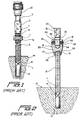
- FIGURE 1 which substantially corresponds to FIGURE 1 of the noted patent, a blind bore 10 has been drilled within a concrete, masonry, rock, or similar foundation 14, and in order to fixedly secure a threaded stud 5 within the drilled bore 10, a capsule or ampule 8 containing adhesive resin materials is disposed within the bottom of the bore or hole 10.
- a drive unit 1 comprises an upper end portion 3 which is adapted to be mounted within a chuck mechanism 12 of a rotary drill, not shown, and a lower end portion 4 which is externally threaded in a manner similar to that of the threaded stud 5.
- An internally threaded nut member 6 is adapted to join the lower externally threaded end portion 4 of the drive unit 1 to the upper end portion of the threaded stud 5 as a result of the convexly shaped end portion 11 of the drive unit 1 being disposed in abutment with the upper planar end portion of the threaded stud 5.
- the threaded stud 5 When the threaded stud 5 is to be fixedly secured within the bore or hole 10 of the foundation or substrate 14, the lower chamfered or tapered end portion 7 of the threaded stud 5 is forced downwardly against the capsule or ampule 8 so as to fracture the same, and upon actuation of the drill tool, not shown, the threaded stud 5 is driven downwardly to the bottom end portion of the bore or hole 10 so as to not only be seated within the lowermost depth portion thereof but to also agitate and fully mix the adhesive resin materials or components together.
- FIGURE 2 which corresponds substantially to FIGURE 1 of this particular patent, a drilled hole 11 is formed within a concrete foundation member 10, and a breakable capsule 12, containing a suitable chemical adhesive material, is disposed within the bottom of the bore 11.
- An externally threaded stud or anchor 13 is adapted have its conically shaped or pointed lower end portion 14 inserted within the drilled bore 11, while the upper end portion of the threaded stud or anchor 13 is adapted to be disposed within a driver 18.
- the lower end portion of the driver 18 is provided with an internally threaded bore 26, and the axially inner end portion of the bore or hole 26 is undercut or radially enlarged as at 27, while the transversely extending end wall of the bore or hole 26 has an axially tapered face 28.
- An adaptor 30 is releasably attached to the upper end portion of the driver 18 by means of a transversely oriented retainer pin 38 and is provided for operatively connecting the driver 18 to a rotary drive means, such as, for example, an electric drill, not shown.
- the adaptor 30 comprises an upper shank portion 31 which is adapted to be disposed within the chuck portion of the drill, and a lower shaft portion 34 which is adapted to be seated within an axial bore 35 formed within the upper body portion 19 of the driver 18.
- the transversely extending pin 38 extends through a transverse bore 40 formed within the upper body portion 19 of the driver 18, as well as through a transverse bore 39 formed within the adaptor shaft portion 34, and is retained in position by means of an O-ring 41 disposed within a peripheral groove 42. It is noted that when the upper end portion of the threaded stud or anchor 13 is disposed within the internally threaded bore or hole portion 26 of the driver 18, the axially tapered face 28 comprising the transversely extending end wall of the bore or hole 26 will be disposed in pressed contact with the convexly shaped upper end portion 15 of the threaded stud or anchor 13.
- Another object of the present invention is to provide a new and improved setting tool which is to be used in connection with the driving insertion and fixation of adhesively bonded threaded rods, studs, anchors, or the like, within concrete, masonry, rock, or similar foundations or underlying substrates, and which effectively overcomes the various operational drawbacks and disadvantages characteristic of PRIOR ART setting tools or driving devices.
- An additional object of the present invention is to provide a new and improved setting tool which is to be used in connection with the driving insertion and fixation of adhesively bonded threaded rods, studs, anchors, or the like, within concrete, masonry, rock, or similar foundations or underlying substrates, and which is relatively simple in structure and comprises a small number of component parts.
- a further object of the present invention is to provide a new and improved setting tool which is to be used in connection with the driving insertion and fixation of adhesively bonded threaded rods, studs, anchors, or the like, within concrete, masonry, rock, or similar foundations or underlying substrates, and which is able to properly engage the threaded stud or anchor so as to operatively drive the same without causing scarring or frictional binding of the same.
- a last object of the present invention is to provide a new and improved setting tool which is to be used in connection with the driving insertion and fixation of adhesively bonded threaded rods, studs, anchors, or the like, within concrete, masonry, rock, or similar foundations or underlying substrates, and which is alternatively capable of being removed from the threaded rod, stud, or anchor fixedly secured within the drilled blind bore pre-formed within the concrete, masonry, rock, or similar foundation or underlying substrate so as to be reuseable in connection with the driving insertion and fixation of other threaded rods, studs, anchors, or the like, within pre-drilled blind bores formed within other concrete, masonry, rock, or similar foundations or underlying substrates, or which is capable of being separated, along a pre-defined line of frangibility, from a nut member portion of the setting tool such that the nut member remaining upon the threaded rod, stud, or anchor is capable of fixing various components to the foundation or underlying substrate.
- a new and improved setting tool which is to be used in connection with the driving insertion and fixation of adhesively bonded threaded rods, studs, anchors, or the like, within concrete, masonry, rock, or similar foundations or underlying substrates, and which effectively comprises a cap having a cup-shaped configuration.
- the cup-shaped cap is internally threaded upon the interior peripheral wall portion thereof, and an axially extending button projects into the cup-shaped member from the closed end wall portion thereof for engaging the free end portion of the threaded rod so as to drivingly insert the threaded rod into the blind bore defined within the underlying substrate or foundation.
- the external periphery of the cup-shaped member has a hexagonal configuration so as to be capable of being driven by means of a hex socket drive, or alternatively, the head portion of the cup-shaped cap member may have a suitable axially extending, geometrically configured socket formed therein for receiving a suitable driving tool having a correspondingly shaped configuration.
- the external peripheral wall portion of the cup-shaped cap member may have an annular recess or notch formed therein so as to effectively provide the peripheral wall portion with predetermined weakened properties along a line of frangibility.
- the new and improved setting tool 110 of the present invention comprises a cap that is adapted to be threadedly mounted upon a free end portion of a threaded rod, anchor, or stud which may have a planar or non-planar surface configuration and which is adapted to be adhesively bonded within a pre-drilled blind bore or hole formed within an underlying substrate or foundation, wherein such substrate or foundation may be formed from a suitable material, such as, for example, rock, masonry, concrete, or the like.
- the new and improved setting tool 110 has a substantially cup-shaped configuration which has a substantially U-shaped cross-sectional configuration symmetrically formed around a longitudinal axis 112, and more particularly, it is seen that the cup-shaped setting tool 110 comprises a transversely extending head section 114 and an axially extending annular wall portion 116 integrally connected to the head section 114.
- the exterior wall structure of the setting tool 110 has a substantially hexagonal or similar geometrical configuration so as to permit the setting tool 110 to be inserted within a correspondingly configured socket portion of a suitable rotary drive tool, not shown, whereby the setting tool 110 can be rotationally driven thereby, or alternatively, the external end surface 118 of the head section 114 is provided with a recessed socket portion 120 for receiving a suitable rotary drive tool, not shown. While the recessed socket portion 120 is illustrated as having a substantially square-shaped con-figuration, the recessed socket portion 120 can have other geometrical configurations which likewise enable the setting tool 110 to be rotatably driven by means of a suitable rotary drive tool, not shown.
- a button member 126 having a substantially circular cross-sectional configuration, is integrally formed upon an interior end wall portion 128 of the head section 114 of the setting tool 110 so as to project axially inwardly within the setting tool 110 and thereby extend toward the open end of the setting tool 110.
- the internal peripheral wall portion 122 of the axially extending annular wall portion 116 is threaded as at 124 so as to permit the setting tool 110 to be threadedly engaged upon a free end portion of a threaded rod, stud, or anchor, as has been illustrated, for example, in FIGURE 2 , and when the setting tool 110 is in fact threadedly engaged upon the free end portion of the threaded rod, stud, or anchor, the free end surface portion 130 of the button member 126, which extends transversely with respect to the longitudinal axis 112 of the setting tool 110, is adapted to engage the free end portion of the threaded rod, stud, or anchor.
- the free end surface portion 130 of the button member 126 is substantially planar, and in this manner, when the setting tool 110 is threadedly secured upon the free end portion of the threaded rod, anchor, or stud, which is to be fixedly adhesively bonded within a pre-drilled blind bore or hole formed within an underlying substrate or foundation, the driving loads transmitted by the button member 126, and the free end portion 130 thereof, to the free end portion of the threaded rod, anchor, or stud, will be substantially uniformly distributed over the surface area of the free end portion 130 of the button member 126 so as not to tend to mar, scar, gouge, or otherwise deleteriously affect the free end portion of the threaded rod, anchor, or stud.
- the structure of the button member 126 does not tend to mar, scar, or gouge the free end portion of the threaded rod, anchor, or stud so as not to in turn cause any corrosion or other structural deterioration of the threaded rod, anchor, or stud as a result of the coating layers thereof being otherwise exposed to environmental conditions.
- the annular wall portion 116 of the setting tool 110 has a predetermined internal diametrical extent comprising a predetermined dimension D 1
- the free end portion 130 of the button member 126 is likewise provided with a predetermined diametrical extent comprising a predetermined dimension D 2 which is substantially less than that of the predetermined diametrical extent dimension D 1 of annular wall portion 116.
- the predetermined diametrical extent dimension D 2 of the free end portion 130 of the button member 126 may be within a range of, for example, approximately twenty-five to fifty percent (25-50%) of the predetermined internal diametrical extent dimension D 1 characterizing the annular wall portion 116.
- the planar surface defined by the free end portion 130 of the button member 126, and the diametrical extent thereof, is large enough so as to substantially uniformly distribute and apply the driving forces of the setting tool 110 to the free end portion of the threaded rod or anchor without in effect concentrating such forces along a point or linear contact locus so as not to deleteriously affect the free end portion of the threaded rod or anchor.
- the diametrical extent of the planar surface defined by means of the free end portion 130 of the button member 126 is small enough so as not to create or generate excessive frictional or binding forces, which are a function of surface area, between the free end portion 130 of the button member 126 and the free end portion of the threaded rod or anchor when the free end portion 130 of the button member 126 is engaged with the free end portion of the threaded anchor or rod during installation of the threaded anchor or rod within the pre-drilled bore or hole provided within the underlying foundation or substrate.
- the button member 126 in connection with the button member 126, and its disposition within the internal space 132 of the setting tool 110, that the button member 126 has a predetermined axial extent such that the free end portion 130 of the button member 126 is disposed at an axial position which is axially beyond the end of the threaded portion 124 which is disposed adjacent to or within the vicinity of the interior end wall portion 128 of the setting tool 110 as disclosed at L in FIGURES 6 and 7 .
- the free end portion 130 of the button member 126 will necessarily engage the free end portion of the threaded rod or anchor prior to the termination of the threaded engagement of the threaded rod or anchor with the end threads of the threaded portion 124 which are disposed adjacent to or within the vicinity of the interior end wall portion 128 of the setting tool 110.
- the free end portion of the threaded rod or anchor can never effectively extend beyond the end threads of the threaded portion 124 which are disposed adjacent to or within the vicinity of the interior end wall portion 128 of the setting tool 110, otherwise such end threads might effectively cut or tap new threads into the interior peripheral side wall portion of the setting tool 110 which would likewise leading to the creation of additional frictional or binding forces.
- the dimension L, which defines the axial dimension that the free end portion of the button member 126 extends beyond the interior end of the threads 124 may comprise, for example, an axial extent equivalent to two times the pitch distance defined between successive threads.
- the entire setting tool 110 can be threadedly disengaged from the free end portion of the threaded rod or anchor so as to again be used as a setting tool in connection with the insertion of additional threaded anchors or rods within the same or other underlying substrates or foundations.
- a final unique feature of the present invention comprises structure integrally incorporated within the setting tool 110 which enables the same to effectively be separated into two parts wherein a first end portion of the setting tool 110 is removed from the threaded anchor or rod while a second nut portion remains threadedly engaged upon the threaded rod or anchor so as to be subsequently utilized in connection with securing auxiliary components to the underlying foundation or substrate.
- annular V-shaped notch or groove 134 is formed within the outer peripheral surface of the annular wall portion 116 at an axial position which is substantially intermediate the opposite ends of the setting tool 110.
- the V-shaped notch or groove 134 therefore defines an annular line of frangibility along which the setting tool 110 can effectively be separated into a first residual member or piece 136 which contains the head section 114 and which is adapted to be threadedly disengaged from the threaded rod or anchor so as to be subsequently discarded, and a second member or piece 138 which comprises a nut member and which is adapted to remain threadedly engaged upon the threaded rod or anchor so as to secure auxiliary components to or upon the underlying foundation or substrate.
- the setting tool 110 may be readily fabricated from any one of a plurality of materials, such as, for example, glass-filled NYLON®, and it is noted that the radially inward depth to which the annular groove or notch 134 is formed will affect the relative torque-resistant strength properties of the setting tool 110. If the radial depth of the annular groove or notch 134 is relatively shallow, then the setting tool 110 will exhibit relatively high torque resistant properties within the vicinity of the annular groove or notch 134 and along the line of frangibility thereof, while conversely, if the radial depth of the annular groove or notch 134 is relatively deep, then the setting tool 110 will exhibit relatively low torque-resistant properties within the vicinity of the annular groove or notch 134 and along the line of frangibility thereof.
- the depth of the annular groove or notch 134 effectively determines the torque limit at which the first residual and second nut members 136,138 can be separated from each other.
- a desired torque limit at which the first and second pieces will be separated from each other may be, for example, two hundred fifty (250) foot-pounds of torque.
- the setting tool 110 can initially be retained upon the free end portion of the threaded rod or anchor until the adhesive material, disposed within the pre-drilled bore or hole of the underlying foundation or substrate, cures and sets, whereupon a predetermined amount of rotational torque can be applied to the setting tool 110.
- the rotational torque applied to the setting tool 110 will cause the setting tool 110 to fracture, along the line of frangibility as defined by means of the annular groove or notch 134, so as to separate into the first residual and second nut members 136,138.
- a pair of wrenches or similar tools can be utilized to grasp the upper and lower end portions of the setting tool 110 whereupon relative torque rotation of the tools in opposite directions will cause the setting tool 110 to be separated into its residual and nut members components 136,138.
- a new and improved setting tool for use in connection with the insertion of threaded rods, anchors, or studs within holes or bores pre-drilled within an underlying substrate or foundation, wherein a button member, having a planar end surface, engages the free end portion of the threaded rod or anchor so as to uniformly distribute the driving forces thereto without causing any gouging or scarring of the same.
- the external side wall portion is provided with an annular notch or groove which provides the setting tool with predetermined torque-resistant properties.
- the setting tool When the torque limit is desirably exceeded, the setting tool is able to be separated into a residual member which may be discarded, and a nut member which may be retained upon the threaded rod or anchor so as to be capable of securing auxiliary components to the underlying foundation or substrate.
Landscapes
- Engineering & Computer Science (AREA)
- Mechanical Engineering (AREA)
- Dowels (AREA)
- Joining Of Building Structures In Genera (AREA)
Applications Claiming Priority (2)
| Application Number | Priority Date | Filing Date | Title |
|---|---|---|---|
| US374233 | 2003-02-25 | ||
| US10/374,233 US20040163496A1 (en) | 2003-02-25 | 2003-02-25 | Setting tool for adhesively bonded threaded rod anchors |
Publications (1)
| Publication Number | Publication Date |
|---|---|
| EP1452277A2 true EP1452277A2 (fr) | 2004-09-01 |
Family
ID=32771437
Family Applications (1)
| Application Number | Title | Priority Date | Filing Date |
|---|---|---|---|
| EP04290440A Withdrawn EP1452277A2 (fr) | 2003-02-25 | 2004-02-19 | Dispositif de pose pour tige d'ancrage filetée collée |
Country Status (3)
| Country | Link |
|---|---|
| US (1) | US20040163496A1 (fr) |
| EP (1) | EP1452277A2 (fr) |
| CA (1) | CA2454624A1 (fr) |
Cited By (1)
| Publication number | Priority date | Publication date | Assignee | Title |
|---|---|---|---|---|
| GB2527823A (en) * | 2014-07-03 | 2016-01-06 | James Kay | Pile buddy |
Families Citing this family (1)
| Publication number | Priority date | Publication date | Assignee | Title |
|---|---|---|---|---|
| US8209891B2 (en) * | 2009-06-12 | 2012-07-03 | Verne Shellhouse | Memorial marker |
Family Cites Families (25)
| Publication number | Priority date | Publication date | Assignee | Title |
|---|---|---|---|---|
| US1566691A (en) * | 1925-12-22 | Stud-bolt tool | ||
| US958980A (en) * | 1908-11-23 | 1910-05-24 | Charles E Chester | Chuck. |
| US1298324A (en) * | 1918-11-18 | 1919-03-25 | Frank M Funk | Stud-driver. |
| US1549041A (en) * | 1924-09-17 | 1925-08-11 | William A Yeagher | Stud-removing tool |
| US2326317A (en) * | 1939-11-22 | 1943-08-10 | Chieago Pneumatic Tool Company | Impact wrench |
| US2336157A (en) * | 1942-04-04 | 1943-12-07 | Gen Motors Corp | Stud driver |
| US2394812A (en) * | 1943-11-06 | 1946-02-12 | Seitz Richard | Lock nut |
| US2622466A (en) * | 1949-04-18 | 1952-12-23 | Vanden Bos | Stud remover and driver |
| US2800820A (en) * | 1954-06-04 | 1957-07-30 | Groov Pin Corp | Driver tool for self tapping inserts, struds, screw bolts, and the like |
| US2933960A (en) * | 1957-06-10 | 1960-04-26 | Studrive Inc | Stud driving chuck |
| US3280666A (en) * | 1964-03-20 | 1966-10-25 | Neuschotz Robert | Tools for installing threaded elements |
| US3244055A (en) * | 1964-03-26 | 1966-04-05 | Schuermann Fritz | Detachable anchor bolts |
| US3292463A (en) * | 1966-01-10 | 1966-12-20 | Titan Tool Co | Wrench adapter |
| US3368430A (en) * | 1966-03-07 | 1968-02-13 | American Steel And Pump Corp | Stud driver and release tools |
| US3963322A (en) * | 1975-01-23 | 1976-06-15 | Ite Imperial Corporation | Torque controlling set screw for use with the cable of solderless connectors, or the like |
| US3978761A (en) * | 1975-06-26 | 1976-09-07 | Thomas & Betts Corporation | Fastener assembly |
| US4404875A (en) * | 1980-07-18 | 1983-09-20 | Usm Corporation | Installer drive unit for chemical anchor |
| US4513643A (en) * | 1982-03-24 | 1985-04-30 | Titan Tool Company | Automatic stud driving tool |
| US4539872A (en) * | 1982-11-24 | 1985-09-10 | Hi-Shear Corporation | Tool for supplying and driving a sequence of threaded fasteners |
| CA1249738A (fr) * | 1985-08-29 | 1989-02-07 | Michael A. Rachanski | Outil de pose de goujons |
| US4652193A (en) * | 1986-02-03 | 1987-03-24 | Hibbs Jerry M | Adhesively secured anchor |
| US4982625A (en) * | 1986-11-10 | 1991-01-08 | A.T. & G. Company, Inc. | Adaptor and driver for an adhesive capsule anchor |
| US4872298A (en) * | 1988-02-12 | 1989-10-10 | Klemic Jr Frank | Concrete anchor bolt setting device |
| DE19704002A1 (de) * | 1997-02-04 | 1998-08-06 | Hilti Ag | Ankerstange für Verbundanker |
| US6416256B1 (en) * | 2000-07-26 | 2002-07-09 | Illinois Tool Works Inc. | Method of making and applying chemical anchoring adhesive |
-
2003
- 2003-02-25 US US10/374,233 patent/US20040163496A1/en not_active Abandoned
- 2003-12-31 CA CA002454624A patent/CA2454624A1/fr not_active Abandoned
-
2004
- 2004-02-19 EP EP04290440A patent/EP1452277A2/fr not_active Withdrawn
Cited By (1)
| Publication number | Priority date | Publication date | Assignee | Title |
|---|---|---|---|---|
| GB2527823A (en) * | 2014-07-03 | 2016-01-06 | James Kay | Pile buddy |
Also Published As
| Publication number | Publication date |
|---|---|
| US20040163496A1 (en) | 2004-08-26 |
| CA2454624A1 (fr) | 2004-08-25 |
Similar Documents
| Publication | Publication Date | Title |
|---|---|---|
| US7070376B1 (en) | Self-drilling, self-anchoring fastener for concrete | |
| US4652193A (en) | Adhesively secured anchor | |
| US5168781A (en) | Drive socket | |
| US4907928A (en) | Fastening member for securement into hard materials | |
| US6598499B1 (en) | Universal setting tool for adhesively bonded rebar and threaded rod anchors | |
| US12180989B2 (en) | Threaded fastener | |
| CA1304609C (fr) | Outil et adaptateur servant a la mise en place de pieces d'ancrage a enrobage adhesif | |
| CA2781763C (fr) | Ensemble boulon autoperceur et ecrou | |
| US20170343025A1 (en) | Self-drilling drywall anchor and a method of securing an anchor in a drywall | |
| US8070405B2 (en) | Self drilling bolt with anchor | |
| SK280863B6 (sk) | Ukotvovací čap na ukotvenie prostredníctvom spojovacej hmoty | |
| CA2994014A1 (fr) | Systeme et methode d'installation de fixation | |
| US7114902B2 (en) | Self-tapping bush-shaped screwed insert | |
| US20040156696A1 (en) | Fastener for fiberglass and other composite structures | |
| EP1452277A2 (fr) | Dispositif de pose pour tige d'ancrage filetée collée | |
| US20040136803A1 (en) | Fastener for fiberglass and other composite structures | |
| EP4308822B1 (fr) | Procédé et vis de nivellement pour installer une fixation | |
| GB2289737A (en) | Anchor system | |
| JPS5813133Y2 (ja) | ボルトの軽量気泡コンクリ−ト用アンカ− | |
| EP0525274A1 (fr) | Moyen de maintien pour recevoir un axe ou tige taraudé externement | |
| AU2019232872A1 (en) | Screw fasteners for use in building construction | |
| JPH02296007A (ja) | インサートナットの固着方法 | |
| JPH03161284A (ja) | アンカボルト打込み用治具 | |
| JPH03161285A (ja) | アンカボルト打込み用治具 |
Legal Events
| Date | Code | Title | Description |
|---|---|---|---|
| PUAI | Public reference made under article 153(3) epc to a published international application that has entered the european phase |
Free format text: ORIGINAL CODE: 0009012 |
|
| AK | Designated contracting states |
Kind code of ref document: A2 Designated state(s): AT BE BG CH CY CZ DE DK EE ES FI FR GB GR HU IE IT LI LU MC NL PT RO SE SI SK TR |
|
| AX | Request for extension of the european patent |
Extension state: AL LT LV MK |
|
| STAA | Information on the status of an ep patent application or granted ep patent |
Free format text: STATUS: THE APPLICATION HAS BEEN WITHDRAWN |
|
| 18W | Application withdrawn |
Effective date: 20050530 |