EP1452655A2 - Dispositif pour l'extraction de l'humidité d'un mur - Google Patents
Dispositif pour l'extraction de l'humidité d'un mur Download PDFInfo
- Publication number
- EP1452655A2 EP1452655A2 EP04250911A EP04250911A EP1452655A2 EP 1452655 A2 EP1452655 A2 EP 1452655A2 EP 04250911 A EP04250911 A EP 04250911A EP 04250911 A EP04250911 A EP 04250911A EP 1452655 A2 EP1452655 A2 EP 1452655A2
- Authority
- EP
- European Patent Office
- Prior art keywords
- wall
- fan
- air guide
- removable
- hole
- Prior art date
- Legal status (The legal status is an assumption and is not a legal conclusion. Google has not performed a legal analysis and makes no representation as to the accuracy of the status listed.)
- Withdrawn
Links
- 238000011282 treatment Methods 0.000 claims description 15
- 239000011449 brick Substances 0.000 claims description 13
- 239000007787 solid Substances 0.000 claims description 10
- 238000000034 method Methods 0.000 claims description 6
- 230000005611 electricity Effects 0.000 claims description 3
- 238000001035 drying Methods 0.000 description 11
- 230000000694 effects Effects 0.000 description 8
- 239000004570 mortar (masonry) Substances 0.000 description 5
- 239000000126 substance Substances 0.000 description 5
- 229920002994 synthetic fiber Polymers 0.000 description 4
- 238000012423 maintenance Methods 0.000 description 3
- 238000009423 ventilation Methods 0.000 description 3
- 238000009825 accumulation Methods 0.000 description 2
- 238000004140 cleaning Methods 0.000 description 2
- 230000002950 deficient Effects 0.000 description 2
- 238000003780 insertion Methods 0.000 description 2
- 230000037431 insertion Effects 0.000 description 2
- 239000000463 material Substances 0.000 description 2
- 238000005192 partition Methods 0.000 description 2
- 239000005871 repellent Substances 0.000 description 2
- 230000000630 rising effect Effects 0.000 description 2
- 241000238631 Hexapoda Species 0.000 description 1
- 239000011358 absorbing material Substances 0.000 description 1
- 230000004888 barrier function Effects 0.000 description 1
- 230000015572 biosynthetic process Effects 0.000 description 1
- 239000004568 cement Substances 0.000 description 1
- 229910010293 ceramic material Inorganic materials 0.000 description 1
- 150000001875 compounds Chemical class 0.000 description 1
- 230000002153 concerted effect Effects 0.000 description 1
- 238000009833 condensation Methods 0.000 description 1
- 230000005494 condensation Effects 0.000 description 1
- 238000010276 construction Methods 0.000 description 1
- 239000000428 dust Substances 0.000 description 1
- 231100000206 health hazard Toxicity 0.000 description 1
- 238000007689 inspection Methods 0.000 description 1
- 238000009434 installation Methods 0.000 description 1
- 239000011810 insulating material Substances 0.000 description 1
- 239000012528 membrane Substances 0.000 description 1
- 230000000149 penetrating effect Effects 0.000 description 1
- 238000000053 physical method Methods 0.000 description 1
- 238000009428 plumbing Methods 0.000 description 1
- 239000011148 porous material Substances 0.000 description 1
- 230000002035 prolonged effect Effects 0.000 description 1
- 230000001681 protective effect Effects 0.000 description 1
- 238000012857 repacking Methods 0.000 description 1
- 230000008439 repair process Effects 0.000 description 1
- 150000003839 salts Chemical class 0.000 description 1
- 238000007789 sealing Methods 0.000 description 1
- 230000003019 stabilising effect Effects 0.000 description 1
- 238000010186 staining Methods 0.000 description 1
- 239000004575 stone Substances 0.000 description 1
- XLYOFNOQVPJJNP-UHFFFAOYSA-N water Substances O XLYOFNOQVPJJNP-UHFFFAOYSA-N 0.000 description 1
Images

Classifications
-
- E—FIXED CONSTRUCTIONS
- E04—BUILDING
- E04B—GENERAL BUILDING CONSTRUCTIONS; WALLS, e.g. PARTITIONS; ROOFS; FLOORS; CEILINGS; INSULATION OR OTHER PROTECTION OF BUILDINGS
- E04B1/00—Constructions in general; Structures which are not restricted either to walls, e.g. partitions, or floors or ceilings or roofs
- E04B1/62—Insulation or other protection; Elements or use of specified material therefor
- E04B1/70—Drying or keeping dry, e.g. by air vents
- E04B1/7069—Drying or keeping dry, e.g. by air vents by ventilating
- E04B1/7076—Air vents for walls
-
- E—FIXED CONSTRUCTIONS
- E04—BUILDING
- E04B—GENERAL BUILDING CONSTRUCTIONS; WALLS, e.g. PARTITIONS; ROOFS; FLOORS; CEILINGS; INSULATION OR OTHER PROTECTION OF BUILDINGS
- E04B1/00—Constructions in general; Structures which are not restricted either to walls, e.g. partitions, or floors or ceilings or roofs
- E04B1/62—Insulation or other protection; Elements or use of specified material therefor
- E04B1/70—Drying or keeping dry, e.g. by air vents
- E04B1/7069—Drying or keeping dry, e.g. by air vents by ventilating
- E04B1/7084—Drying or keeping dry, e.g. by air vents by ventilating with Knappen systems, i.e. atmospheric siphons
Definitions
- the present invention relates to a device to abstract moisture from a wall or similar, more particularly from a wall made of masonry, concrete or other moisture-absorbing material.
- Rising damp caused by ground moisture being absorbed into brick and masonry walls, is a major cause of decay to masonry materials such as stone, brick and mortar. Even when mild it can cause unsightly crumbling of exterior masonry and staining of internal finishes. When severe it is a potential health hazard to building occupants due to high humidity levels and the growth of moulds. When coupled with high salt concentrations, severe damp can cause extensive fretting and crumbling of the lower parts of walls, requiring difficult and expensive repairs.
- Moisture removing devices such as those disclosed in NL183,148 or EP0829587, offer an alternative to DPC treatments.
- Such devices typically comprise a frame which is inserted and secured in a hole fabricated (for example by removing bricks from the outer wall) in the wall to be treated.
- Prior art devices also comprise a separate body that extends outside the outer wall as well as the hole, which is provided with a partition, such that the body and the partition divide the hole into two chambers, leaving a free passage between them.
- prior art device EP 0829587 was realised.
- the device works in a similar way to that disclosed in NL 183,148, and has an air guide channel around which the dry air flows and displaces the damp air contained within the cavity, but circumvents the requirement for bricking up the cavity wall into which it is installed through the use of means which form a cover between the air guide channel and the surrounding cavity.
- powered fans ensures that air flow through the device (and thus the drying process) is maintained irrespective of external air currents moving over the external wall and the device, resulting in consistent and rapid drying times for a wall which is treated.
- a device to abstract moisture from a wall or similar comprising a housing having an air guide means, an at least one removable fan, an at least one motor to drive the at least one removable fan, characterised in that the device can be applied in a hole in a wall, the hole having a front at its exterior portion and a back at its interior portion, the air guide means defining an air guide channel between at least first and second openings, the at least one fan being positioned in the at least first and second openings, such that air driven by the first fan through the first opening flows through the air guide channel and through the second opening, thereby carrying off moisture originating from the wall.
- the at least one removable fan may be positioned to draw air into the first opening.
- the air that circulates through the air guide channel may exit the device through the second opening due to an increase in air pressure within the hole, resulting in a drying effect.
- the air guide means may be removable from the housing, thereby facilitating access to the hole in the wall and any cleaning or maintenance of the device or hole that may be required.
- the housing may additionally comprise a removable vented front section with vents sufficiently narrow to prevent the entry and accumulation of unwanted foliage, twigs and debris within the device or the hole in the wall.
- the vented front section may serve to minimise the vigilance and maintenance required to ensure a concerted and prolonged drying effect on a wall to be treated.
- the vented front section may be manufactured from a lightweight, durable, resilient synthetic material such as plastic.
- the at least one removable fan may be an axial flow fan, i.e. a fan where the airflow is straight through the propeller.
- axial flow fan i.e. a fan where the airflow is straight through the propeller.
- propeller fans efficiently move large volumes of air at low pressures, and they are normally used for general ventilation through a wall.
- the at least one removable fan may comprise a synthetic material.
- the removable fan may be water and weatherproof, and easily maintainable.
- the fan may be easily removable from the housing of the device, such that it can be maintained, replaced, or cleaned, or provide access to the air guide channel and the hole in the wall.
- the device may comprise more than two fans.
- a device In treating a particularly damp wall, or a wall with a large damp area, a device may be used which comprises two or more fans located within each of the first and second openings. The fans may be positioned within the first and second opening so as to maximise air flow into and out of the air guide channel, thereby improving the efficiency of the device.
- the air guide means may comprise a vertically separating wall, preferably extending over the full or nearly full height of the device, which divides the hole into two adjacent chambers, whereby a passage is left between the two chambers.
- the passage may be located toward or at the back of (i.e. the innermost portion of) the hole in the wall, such that the air moving from one chamber to the other through the passage is close to or contacts the wall under treatment, thereby maximising the drying effect produced by the device.
- the vertically separating wall may comprise e.g. ceramic material or a synthetic material such as plastic.
- the device may comprise first and second openings, each of which may comprise a removable fan and a motor to drive the fan.
- the air flow created by each of the fans may be of opposite polarity, such that the fan positioned in the first opening serves to draw dry air into the air guide channel thereby contacting the damp wall, and the fan positioned in the second opening serves to draw the resulting damp air out of the air guide channel and out of the device.
- the flow rate of a removable fan may be adjustable.
- the flow rates of the fans in a device comprising two fans may be different, or they may be equal, such that the volume of air drawn into the device by a first fan is equal to the volume of air drawn out of the device by a second fan.
- the flow of air through the air guide channel and over the damp wall is controlled and localised rather than being turbulent, and in the case of a cavity wall, this results in minimal disturbance of warm air within the cavity. Since the majority of the volume of warm air in the cavity is not disturbed by turbulent air flow through the device, the amount of this warm air drawn out of the device by a second fan, is minimised, thereby minimising temperature decrease within the cavity, and maintaining a higher temperature within the wall, and thus the building.
- the device may be installed for use in a hole realised in either a cavity wall or a solid wall.
- the housing of the device may comprise a synthetic material which is durable and resilient.
- the housing may comprise a means by which the at least one removable fan can be mounted in position and stabilised, for example through the use of grooves or mounting pins. Other means of mounting, positioning and stabilising the fans are envisaged, and will be well known to a person skilled in the art.
- the guide means may be removable, and the housing configured to enable the convenient removal and insertion of the guide means.
- the housing may comprise a non-vented front section which may be removably attachable.
- the non-vented front section may be attached to the housing thereby completely closing or sealing off the hole in the wall from the outside, and circumventing the requirement to remove the housing from the wall and brick up the hole.
- the provision of the non-vented front section thereby reduces labour costs and saves time and money.
- the non-vented front section may be coloured and contoured to blend in with the brickwork of the treated wall.
- the non-vented front section may be removed, and the air guide means, and at least one fan and motor may be installed back into the housing of the device, and the vented front section may be replaced.
- the wall may be treated using the device until such a time as the damp is satisfactorily treated, and then the components of the device may be removed and the hole in the wall sealed up again using the non-vented front section.
- the non-vented front section may comprise an insulating material on the innermost side, i.e. the side which faces into the hole in the wall, to so as to prevent heat loss from the hole.
- one or more insulating bricks may be provided, which can be used to fill the hole in the wall prior to attaching the non-vented front section.
- the fans, motors, air guide means and front sections may all be easily removable from the housing of the device.
- the modular nature of the device according to the present invention and its components means that the hole in the wall is readily accessible for cleaning, maintenance and inspection purposes.
- the device may be partially or substantially contained within a house brick, which may then be easily installed into a hole in the wall to be treated.
- the device may be installed into a wall by making an opening in the either the solid wall or the outer wall of a cavity wall.
- the device contained within the housing may be inserted into the hole in the wall, and secured using mortar, cement or similar.
- the removably attachable vented front section may then be attached in place, thereby preventing build up of debris within the device and the hole in the wall.
- the device may be substantially the same size as a house brick or share substantially similar dimensions to the bricks used to create the wall to be treated, such that the number of bricks that have to be removed in order to create the hole into which the device is to be inserted is kept to a minimum.
- the at least one motor to drive the at least one removable fan may be powered by electricity, solar power, or magnetic power.
- the motor may comprise a power switch.
- a loop of mains cable can be passed around the house and fastened to the external walls, or can e.g. pass along the length of a cavity in the wall, such that the power leads attached to a fan motor can be readily attached to the mains power cable, for example through splicing, or with the aid of spikes which allow the lead to tap into the main power supply and drive the motor and the fan.
- solar panels to power the fans of the device is also envisaged and these are well known to a person skilled in the art.
- the fans may be controlled through individual power switches, or through the use of a timing device - for example they may be set to operate for a designated time period per day, or at a certain time of the day, for example when it is hottest (e.g. around midday).
- the fans of the device may be controlled by a control unit located inside the building under treatment, such that a user may centrally operate the one or more devices installed in the walls of the building from inside. Timing devices are not new and will be well known to a person skilled in the art.
- a kit of parts comprising a housing having an air guide means, at least one removable fan, at least one motor to drive the at least one removable fan, and an additional at least one removable fan and motor, characterised in that the device can be applied in a hole in a wall, the hole having a front at its exterior portion and a back at its interior portion, the air guide means defining an air guide channel between at least first and second openings, the at least one fan being positioned in the at least first and second openings, such that air driven by the first fan through the first opening flows through the air guide channel and through the second opening, thereby carrying off moisture originating from said wall.
- the kit of parts may comprise one or more devices together with replacement fans and motors, spare parts, or components thereof, and thus provide a user with everything required in order to treat a damp within a solid or cavity wall.
- the kit of parts may contain a device according to the second aspect of the present invention in which the air guide means is removable from the housing.
- the kit of parts may contain a device according to the second aspect of the present invention in which the housing additionally comprises a removable vented front section.
- the kit of parts may contain a device according to the second aspect of the present invention in which the housing additionally comprises a non-vented front section.
- a method of treatment of damp in a wall or similar, the wall defining internal and external surfaces comprising the steps of:
- the components of the device may be removed to leave the housing in the hole in the wall.
- a non-vented front section may be attached to the housing of the device to seal up the hole in the wall, circumventing the requirement to remove the housing and fill in the hole with bricks and mortar. If the damp problem resurfaces, the device may be reassembled by removing the non-vented front section and installing the air guide means, at least one fan and motor and a vented front section.
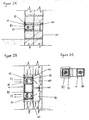
- a device (10) to abstract moisture from a cavity wall (20) or solid wall (30) comprises an air guide means (40), an at least one removable fan (50), an at least one motor (60) to drive the at least one removable fan, a power switch (65), and a housing (70) comprising a removable vented front section (80), characterised in that the air guide means is removably positioned within the housing, and the housing is applied in a hole (90) in a wall, defining an air guide channel (100) between at least first and second openings (110, 120), the at least one fan (50) being positioned in the at least first and second openings (110, 120), such that air driven by the at least one fan (50) through the first opening (110) flows through the air guide channel (100) and through the second opening (120), thereby carrying off moisture originating from the cavity wall (20) or solid wall (30).
- the operation of the device (10) is based on the fact that the powered removable fan (50)in a first opening (110), operated by a power switch (65) draws air into the device (10) (flow F1), which is channelled though the air guide channel (100) and blown out of the device (10) by the fan (50) in the second opening (120) (flow F2), thereby creating a drying effect.
- the moisture from the cavity wall (20) or the solid wall (30) saturates the air in the hole, and this humid air is sucked out of the hole (90) and blown out of the device by a fan (50) positioned in a second opening (120).
- Access to a hole (90) in either a cavity wall (20) or solid wall (30) may be obtained by removing the vented front section (80) from the housing (70) of the device (10) and removing the at least one fan (50) and motor (60), and the air guide means (40).
- the hole (90) may be inspected for damp, or cleaned, or components of the device (10) may be replaced or maintained. If the damp requires further treatment, the device may be reassembled and treated as described previously. If the treated wall requires no further treatment, the hole (90) in the wall (20, 30) may be sealed off by attaching a non-vented front section (not shown) to the housing (70) of the device (10). This non-vented front section may be removed at a later stage to check the status of the previously treated wall, and should the wall require further treatment, the various components of the device (10) may be assembled within the housing (70), and the wall ventilated as described previously.
Landscapes
- Engineering & Computer Science (AREA)
- Architecture (AREA)
- Physics & Mathematics (AREA)
- Electromagnetism (AREA)
- Civil Engineering (AREA)
- Structural Engineering (AREA)
- Structures Of Non-Positive Displacement Pumps (AREA)
Applications Claiming Priority (2)
| Application Number | Priority Date | Filing Date | Title |
|---|---|---|---|
| GB0304123A GB0304123D0 (en) | 2003-02-24 | 2003-02-24 | Brick for extracting moisture from walls |
| GB0304123 | 2003-02-24 |
Publications (2)
| Publication Number | Publication Date |
|---|---|
| EP1452655A2 true EP1452655A2 (fr) | 2004-09-01 |
| EP1452655A3 EP1452655A3 (fr) | 2006-01-25 |
Family
ID=9953520
Family Applications (1)
| Application Number | Title | Priority Date | Filing Date |
|---|---|---|---|
| EP04250911A Withdrawn EP1452655A3 (fr) | 2003-02-24 | 2004-02-20 | Dispositif pour l'extraction de l'humidité d'un mur |
Country Status (2)
| Country | Link |
|---|---|
| EP (1) | EP1452655A3 (fr) |
| GB (1) | GB0304123D0 (fr) |
Cited By (1)
| Publication number | Priority date | Publication date | Assignee | Title |
|---|---|---|---|---|
| FR2920796A1 (fr) * | 2007-09-06 | 2009-03-13 | Alize Advance Sarl Soc Respons | Procede et dispositif pour extraire un gaz d'une structure maconnee |
Citations (1)
| Publication number | Priority date | Publication date | Assignee | Title |
|---|---|---|---|---|
| EP0829587A1 (fr) | 1996-09-13 | 1998-03-18 | Schrijver Systeem Vochtbestrijding N.V., naamloze vennootschap. | Dispositif perfectionnée pour enlever l'humidité d'un mur |
Family Cites Families (3)
| Publication number | Priority date | Publication date | Assignee | Title |
|---|---|---|---|---|
| JPH10121647A (ja) * | 1996-10-24 | 1998-05-12 | Nabeshima Yukio | 成型ブロック |
| US5881951A (en) * | 1997-09-18 | 1999-03-16 | Carpenter; Peter W. | Ventilator for beneath enclosed structures |
| DE19914846A1 (de) * | 1999-04-01 | 2000-10-26 | Alfred Doerle | Verfahren und Vorrichtung zum Austrocknen von feuchten Bauwerken |
-
2003
- 2003-02-24 GB GB0304123A patent/GB0304123D0/en not_active Ceased
-
2004
- 2004-02-20 EP EP04250911A patent/EP1452655A3/fr not_active Withdrawn
Patent Citations (1)
| Publication number | Priority date | Publication date | Assignee | Title |
|---|---|---|---|---|
| EP0829587A1 (fr) | 1996-09-13 | 1998-03-18 | Schrijver Systeem Vochtbestrijding N.V., naamloze vennootschap. | Dispositif perfectionnée pour enlever l'humidité d'un mur |
Cited By (2)
| Publication number | Priority date | Publication date | Assignee | Title |
|---|---|---|---|---|
| FR2920796A1 (fr) * | 2007-09-06 | 2009-03-13 | Alize Advance Sarl Soc Respons | Procede et dispositif pour extraire un gaz d'une structure maconnee |
| WO2009044047A3 (fr) * | 2007-09-06 | 2009-05-28 | Alize Advance | Procede et dispositif pour extraire un gaz d'une structure maconnee |
Also Published As
| Publication number | Publication date |
|---|---|
| GB0304123D0 (en) | 2003-03-26 |
| EP1452655A3 (fr) | 2006-01-25 |
Similar Documents
| Publication | Publication Date | Title |
|---|---|---|
| US9062454B1 (en) | Dual ventilation process | |
| US5881951A (en) | Ventilator for beneath enclosed structures | |
| KR20080088376A (ko) | 지열과 지습을 이용한 공조순환장치 | |
| US7789740B2 (en) | Crawlspace air apparatus | |
| KR101518239B1 (ko) | 건축용 단열 복합 판넬의 조립 및 설치구조 | |
| KR100480006B1 (ko) | 에어하우스 | |
| US20070293139A1 (en) | System and Method for Inhibiting Moisture and Mold in Structures | |
| DE20300465U1 (de) | Be- und Entlüftungsanlage mit Gegenstrombetrieb | |
| US1968680A (en) | Ventilating apparatus for buildings | |
| JP5636397B2 (ja) | 空調システムとその構築方法 | |
| KR101012282B1 (ko) | 건축물의 벽체에 형성된 환기 구조 | |
| JP2008261535A (ja) | 地中熱を利用した省エネ恒温換気システム | |
| JPH11229670A (ja) | 墓地納骨室乾燥装置 | |
| EP3090105B1 (fr) | Dispositif conçu pour extraire l'humidité d'un mur | |
| KR100622455B1 (ko) | 무지주 다층 비닐하우스의 환기장치 | |
| KR200281414Y1 (ko) | 통풍용 공기구멍을 갖는 가옥형 납골묘 | |
| KR20060030589A (ko) | 건물용 배기덕트 구조물 | |
| KR200281415Y1 (ko) | 가옥형 납골묘의 통풍구 구조 | |
| KR200383875Y1 (ko) | 납골묘 | |
| KR100714238B1 (ko) | 오염물 제거장치가 구비된 계사 | |
| JP2005350890A (ja) | 建物の換気構造 | |
| KR200359006Y1 (ko) | 통풍구를 갖는 납골묘 | |
| JPS587048A (ja) | 床下換気施工法 | |
| KR100892051B1 (ko) | 시공후 배수구 청소가 가능한 콘크리트 옹벽의 치장벽돌조적용 통기배수구 | |
| JPH1183102A (ja) | 換気口ユニット |
Legal Events
| Date | Code | Title | Description |
|---|---|---|---|
| PUAI | Public reference made under article 153(3) epc to a published international application that has entered the european phase |
Free format text: ORIGINAL CODE: 0009012 |
|
| AK | Designated contracting states |
Kind code of ref document: A2 Designated state(s): AT BE BG CH CY CZ DE DK EE ES FI FR GB GR HU IE IT LI LU MC NL PT RO SE SI SK TR |
|
| AX | Request for extension of the european patent |
Extension state: AL LT LV MK |
|
| PUAL | Search report despatched |
Free format text: ORIGINAL CODE: 0009013 |
|
| AK | Designated contracting states |
Kind code of ref document: A3 Designated state(s): AT BE BG CH CY CZ DE DK EE ES FI FR GB GR HU IE IT LI LU MC NL PT RO SE SI SK TR |
|
| AX | Request for extension of the european patent |
Extension state: AL LT LV MK |
|
| AKX | Designation fees paid | ||
| REG | Reference to a national code |
Ref country code: DE Ref legal event code: 8566 |
|
| STAA | Information on the status of an ep patent application or granted ep patent |
Free format text: STATUS: THE APPLICATION IS DEEMED TO BE WITHDRAWN |
|
| 18D | Application deemed to be withdrawn |
Effective date: 20060901 |