EP1452670B1 - Verfahren zur Verstärkung eines Bauteils und Bauteil - Google Patents
Verfahren zur Verstärkung eines Bauteils und Bauteil Download PDFInfo
- Publication number
- EP1452670B1 EP1452670B1 EP04290351A EP04290351A EP1452670B1 EP 1452670 B1 EP1452670 B1 EP 1452670B1 EP 04290351 A EP04290351 A EP 04290351A EP 04290351 A EP04290351 A EP 04290351A EP 1452670 B1 EP1452670 B1 EP 1452670B1
- Authority
- EP
- European Patent Office
- Prior art keywords
- modules
- prefabricated
- building element
- prefabricated modules
- connectors
- Prior art date
- Legal status (The legal status is an assumption and is not a legal conclusion. Google has not performed a legal analysis and makes no representation as to the accuracy of the status listed.)
- Expired - Lifetime
Links
- 238000000034 method Methods 0.000 title claims abstract description 31
- 230000003014 reinforcing effect Effects 0.000 title claims abstract description 18
- 239000011230 binding agent Substances 0.000 claims abstract description 34
- 239000004570 mortar (masonry) Substances 0.000 claims description 18
- 230000002787 reinforcement Effects 0.000 claims description 17
- 239000004567 concrete Substances 0.000 claims description 15
- 230000006835 compression Effects 0.000 claims description 8
- 238000007906 compression Methods 0.000 claims description 8
- 229920005989 resin Polymers 0.000 claims description 7
- 239000011347 resin Substances 0.000 claims description 7
- 239000000835 fiber Substances 0.000 claims description 5
- 238000005452 bending Methods 0.000 claims description 4
- 239000003365 glass fiber Substances 0.000 claims description 4
- 238000009417 prefabrication Methods 0.000 claims description 3
- 229910000831 Steel Inorganic materials 0.000 claims description 2
- 239000010959 steel Substances 0.000 claims description 2
- OKTJSMMVPCPJKN-UHFFFAOYSA-N Carbon Chemical compound [C] OKTJSMMVPCPJKN-UHFFFAOYSA-N 0.000 claims 1
- 229910052799 carbon Inorganic materials 0.000 claims 1
- 235000019592 roughness Nutrition 0.000 claims 1
- 238000010276 construction Methods 0.000 abstract description 23
- 238000009434 installation Methods 0.000 description 9
- 239000000463 material Substances 0.000 description 9
- 239000004575 stone Substances 0.000 description 6
- 230000005540 biological transmission Effects 0.000 description 5
- 238000007789 sealing Methods 0.000 description 5
- 239000011449 brick Substances 0.000 description 4
- 239000003822 epoxy resin Substances 0.000 description 4
- 229920000647 polyepoxide Polymers 0.000 description 4
- 229920000049 Carbon (fiber) Polymers 0.000 description 3
- VYPSYNLAJGMNEJ-UHFFFAOYSA-N Silicium dioxide Chemical compound O=[Si]=O VYPSYNLAJGMNEJ-UHFFFAOYSA-N 0.000 description 3
- 239000000853 adhesive Substances 0.000 description 3
- 230000001070 adhesive effect Effects 0.000 description 3
- 239000004917 carbon fiber Substances 0.000 description 3
- 230000015556 catabolic process Effects 0.000 description 3
- 238000006731 degradation reaction Methods 0.000 description 3
- 230000001788 irregular Effects 0.000 description 3
- 239000002023 wood Substances 0.000 description 3
- 230000008901 benefit Effects 0.000 description 2
- 239000000203 mixture Substances 0.000 description 2
- 239000003351 stiffener Substances 0.000 description 2
- 229920003002 synthetic resin Polymers 0.000 description 2
- 239000000057 synthetic resin Substances 0.000 description 2
- 235000008733 Citrus aurantifolia Nutrition 0.000 description 1
- 235000011941 Tilia x europaea Nutrition 0.000 description 1
- 229920006231 aramid fiber Polymers 0.000 description 1
- 229920003235 aromatic polyamide Polymers 0.000 description 1
- 239000011248 coating agent Substances 0.000 description 1
- 238000000576 coating method Methods 0.000 description 1
- 230000007797 corrosion Effects 0.000 description 1
- 238000005260 corrosion Methods 0.000 description 1
- 238000005336 cracking Methods 0.000 description 1
- 230000001934 delay Effects 0.000 description 1
- 239000004744 fabric Substances 0.000 description 1
- 239000011152 fibreglass Substances 0.000 description 1
- 238000009415 formwork Methods 0.000 description 1
- 239000003517 fume Substances 0.000 description 1
- 239000011521 glass Substances 0.000 description 1
- 239000011440 grout Substances 0.000 description 1
- 230000008595 infiltration Effects 0.000 description 1
- 238000001764 infiltration Methods 0.000 description 1
- 239000012212 insulator Substances 0.000 description 1
- 239000004571 lime Substances 0.000 description 1
- 239000012528 membrane Substances 0.000 description 1
- 239000002184 metal Substances 0.000 description 1
- VNWKTOKETHGBQD-UHFFFAOYSA-N methane Chemical compound C VNWKTOKETHGBQD-UHFFFAOYSA-N 0.000 description 1
- 230000004048 modification Effects 0.000 description 1
- 238000012986 modification Methods 0.000 description 1
- 238000010422 painting Methods 0.000 description 1
- 239000002245 particle Substances 0.000 description 1
- 239000000843 powder Substances 0.000 description 1
- 239000010453 quartz Substances 0.000 description 1
- 238000011084 recovery Methods 0.000 description 1
- 238000000926 separation method Methods 0.000 description 1
- 229910021487 silica fume Inorganic materials 0.000 description 1
- 239000000377 silicon dioxide Substances 0.000 description 1
- 239000002002 slurry Substances 0.000 description 1
- 239000002689 soil Substances 0.000 description 1
- 125000006850 spacer group Chemical group 0.000 description 1
- 229910001220 stainless steel Inorganic materials 0.000 description 1
- 239000010935 stainless steel Substances 0.000 description 1
- 239000002699 waste material Substances 0.000 description 1
- XLYOFNOQVPJJNP-UHFFFAOYSA-N water Substances O XLYOFNOQVPJJNP-UHFFFAOYSA-N 0.000 description 1
Images


Classifications
-
- E—FIXED CONSTRUCTIONS
- E04—BUILDING
- E04G—SCAFFOLDING; FORMS; SHUTTERING; BUILDING IMPLEMENTS OR AIDS, OR THEIR USE; HANDLING BUILDING MATERIALS ON THE SITE; REPAIRING, BREAKING-UP OR OTHER WORK ON EXISTING BUILDINGS
- E04G23/00—Working measures on existing buildings
- E04G23/02—Repairing, e.g. filling cracks; Restoring; Altering; Enlarging
- E04G23/0218—Increasing or restoring the load-bearing capacity of building construction elements
-
- E—FIXED CONSTRUCTIONS
- E04—BUILDING
- E04G—SCAFFOLDING; FORMS; SHUTTERING; BUILDING IMPLEMENTS OR AIDS, OR THEIR USE; HANDLING BUILDING MATERIALS ON THE SITE; REPAIRING, BREAKING-UP OR OTHER WORK ON EXISTING BUILDINGS
- E04G23/00—Working measures on existing buildings
- E04G23/02—Repairing, e.g. filling cracks; Restoring; Altering; Enlarging
- E04G23/0218—Increasing or restoring the load-bearing capacity of building construction elements
- E04G23/0233—Increasing or restoring the load-bearing capacity of building construction elements of vaulted or arched building elements
-
- E—FIXED CONSTRUCTIONS
- E04—BUILDING
- E04G—SCAFFOLDING; FORMS; SHUTTERING; BUILDING IMPLEMENTS OR AIDS, OR THEIR USE; HANDLING BUILDING MATERIALS ON THE SITE; REPAIRING, BREAKING-UP OR OTHER WORK ON EXISTING BUILDINGS
- E04G23/00—Working measures on existing buildings
- E04G23/02—Repairing, e.g. filling cracks; Restoring; Altering; Enlarging
- E04G23/0218—Increasing or restoring the load-bearing capacity of building construction elements
- E04G2023/0251—Increasing or restoring the load-bearing capacity of building construction elements by using fiber reinforced plastic elements
Definitions
- the present invention relates to the field of reinforcing masonry construction structures, wood or otherwise, extending between two support points and working in bending as a beam or in compression as a vault.
- the invention applies in particular to old buildings and recent constructions in aggressive environment, especially marine.
- the restoration of a vault of a vault arch in the event of cracking, degradation, deformation can be achieved either by lime slurry, the success of this process being random, or by replacing the degraded elements. or broken requiring scaffolding, or even a reconstruction of the structure.
- the document GB 2,296,276 discloses a method of reinforcing the concrete deck of a bridge or the like. According to the method, the pavement layer is removed and a layer of adhesive is applied to the concrete deck. Next, a plurality of first panels made of a material having a similar or greater strength than that of the concrete deck are laid on the adhesive to form a first reinforcing layer. A sheet-like reinforcement is then placed above the regions of the concrete deck which have a tension of their upper surface, for example those situated above beams. Then, adhesive is applied again and covered with a plurality of second panels, which are similar to the first panels. Finally, the pavement layer is reinstalled.
- the document FR 2,817,575 discloses a structure and a method of reinforcing a masonry extending between two bearing points and comprising a plurality of mutually compressive parts, each part being frictionally held on the adjacent parts.
- the structure comprises a working assembly disposed on an upper surface of the masonry structure and comprising at least two tensile or compressive force recovery layers and at least one spacer means between said two layers.
- the working assembly is made of materials with coefficients of expansion and elasticity close to those of the material constituting the masonry.
- the document FR 2 792 354 constitutes the closest state of the art.
- the invention aims to simplify the implementation of the reinforcement by facilitating its installation.
- the invention also aims to reduce the bulk of the reinforcement.
- the connectors are fixed in the prefabricated modules before adding said prefabricated modules to the building element.
- the connectors can be fixed in prefabricated modules at the factory. Factory prefabricated modules can also benefit from a composition and a more regular particle size than a mortar or concrete spoiled on site.
- the connectors can be fixed in the prefabricated modules during the prefabrication of said modules.
- the connectors are fixed in the building element before the prefabricated modules are added to the building element.
- This variant is well suited to a construction element having an irregular surface.
- a layer of binder is spread on the upper surface of the building element before the prefabricated modules are added to the building element.
- the binder allows a transmission of mechanical forces between the construction element and the prefabricated modules.
- binder is spread between the prefabricated modules, after their installation. This ensures the transmission of mechanical forces between the different prefabricated modules.
- the binder is provided between the construction element and the prefabricated modules after the prefabricated modules have been added to the building element.
- the construction element is a beam.
- the beam may be a stone lintel, a concrete beam or a metal beam.
- the building element is an arch, for example stone or brick.
- the prefabricated modules comprise concrete.
- the prefabricated modules can be made of fiber concrete or concrete loaded with silica fumes.
- the connectors are rods based on fibers, for example glass or carbon fibers and epoxy resin.
- the binder comprises a resin mortar, for example based on epoxy resin.
- the prefabricated modules are in the form of polygonal plates whose edges are provided with reliefs designed to promote the transmission of mechanical forces to neighboring prefabricated modules.
- the prefabricated modules can be arranged in one layer.
- the prefabricated modules can be in a square shape with a triangular tooth on their edges, rectangular in shape with a round or sinusoidal toothing, or triangular in shape with a partial overlap allowing a connector to cross two prefabricated modules.
- the invention also proposes a construction element disposed between at least two supports and working in bending or compression, said building element comprising a reinforcement disposed on an upper face of said construction element and provided with a plurality of prefabricated reinforcement modules. connectors connecting said prefabricated modules and said building element, and a binder disposed between said prefabricated modules and said building element.
- a beam 1 for example made of wood, has an upper surface 1a on which a reinforcement 2 is arranged.
- the reinforcement 2 comprises a plurality of prefabricated reinforcement modules 3, a plurality of connectors, here two connectors 4, 5, per module prefabricated 3, a layer of binder 6 disposed between the prefabricated modules 3 and the upper surface 1a of the beam 1, and a layer of binder 7 disposed between the prefabricated modules 3.
- a plurality of joists 8 rest at one of their ends on the upper surface 1a of the beam 1.
- a floor 9 is fixed on the joists 8.
- the height of the joists 8 may be of the order of 0.15 m. for example.
- the reinforcement 2 can be realized as follows.
- the modules 3 are prefabricated in series in an industrial establishment, with the aim of reducing costs and constancy of their mechanical characteristics. For sites with special requirements, the shape of the modules 3 can to be adapted.
- the connectors 4, 5 are secured to the modules 3 during prefabrication, and arranged according to a predefined template. On the site where the beam 1 is, it clears access to the upper surface 1a by removing the floors, insulators, etc., which cover it.
- a plurality of blind holes is then drilled in the beam 1 from the upper surface 1a according to the same template as that cited above. These terminal holes are intended to accommodate the end of the connectors 4, 5 opposite to that embedded in the prefabricated modules 3. It is also possible to dig in the upper surface 1a of the beam 1 a plurality of notches or notches favoring the future bonding of the binder layer 6 and thus allowing a better transmission of mechanical forces, including shear between the beam 1 and the reinforcement 2, in order to increase the working section of the reinforced beam.
- the lower surface 3a of the prefabricated modules 3 is advantageously provided with concavities and asperities allowing better adhesion with the binder layer 6.
- the blind holes dug in the beam 1 are then filled with a resin mortar and arranging the layer 6 made of the same resin mortar on the upper surface 1a.
- the prefabricated modules 3 are then placed by placing the lower ends of the connectors 4, 5 in the blind holes. Once two adjacent prefabricated modules 3 are installed, the slot which separates them is filled with binder 7 also made of resin mortar.
- the resin mortar is advantageously a mortar based on epoxy resin, whether or not loaded with quartz, glass fibers, carbon fibers, etc. This mortar must be able to be used at atmospheric pressure and have a setting without shrinkage.
- the connectors which make it possible to secure the prefabricated modules 3 and the beam 1, are made of materials having good mechanical properties and insensitive to corrosion, for example glass fiber, carbon fiber, aramid fiber high-strength steel, especially stainless steel.
- the connectors can be in the form of straight rods, with a diameter of the order of 5 to 30 mm, or in the form of U-shaped bent rods such as a staple, the bottom of the U being embedded in a module 3 or disposed on its upper surface.
- the connectors have a length very slightly less than the height of the reinforced beam, to take the sharp forces.
- the prefabricated modules 3 can be made from concrete. This concrete can be armed. Preferably, a high mechanical strength concrete, such as a concrete filled with fibers or powders, of the silica fume type, will be used. It will thus be possible to reduce the thickness of the prefabricated modules 3 and reduce their mass, which facilitates their installation or makes it possible, for an equal mass, to enlarge their dimensions and to reduce their number. In addition, the reinforcement will be of lower height with equal strength which has a decisive advantage in some projects, especially to maintain the height of the original floor. On the figure 1 it can be seen that the reinforcement 2 has a height substantially equal to that of the joists 8.
- prefabricated modules 3 with a length of between 0.5 and 1.2 meters, for example of the order of 1 meter and of variable width depending on the intended application and the width 1.
- Such modules can be easily handled by a single operator, even in places of difficult access.
- the invention allows a simplified installation of the reinforcement, avoids the implementation of formwork which is always time consuming, and thus allows a labor saving and faster execution of construction sites.
- the prefabricated module 3 comprises a shoulder of reduced thickness 10 disposed in the lower position, in contact with the binder layer 6.
- the prefabricated module adjacent to the prefabricated module 3 comprises an upper shoulder 12 which covers the shoulder 10 of the prefabricated module 3.
- the space 13 remaining between the shoulders 10 and 12 is filled with a binder layer which will advantageously be disposed after the installation of the prefabricated module 3 and before that of the adjacent prefabricated module.
- a connector 5 is fixed to the beam 1, to the shoulder 8 of the prefabricated module 3 and to the shoulder 10 of the adjacent prefabricated module, and ensures not only the connection with the beam 1, but also the mutual connection of the prefabricated modules 3.
- the connector 5 may, in a first variant be, prior to installation, independent of the prefabricated modules 3.
- the connector 5 is then first attached to the beam 1 by sealing with a binder in the hole one-eyed planned to welcome him.
- the binder layer 6 is placed on the upper surface 1a of the beam 1
- the prefabricated module 3 is placed on the binder layer 6, the shoulder 8 must then be provided with a through hole intended to accommodate the part remained free of the connector 12.
- the hole, not shown, is filled with the shoulder 8, a layer of binder is placed on the shoulder 8 and the end edges of the prefabricated module 3.
- the adjacent prefabricated module whose shoulder 10 is also provided with a through hole, not shown. This through hole receives the free end of the connector 5 and is then filled with binder.
- FIG. 3 On the figure 3 is illustrated a portion of a prefabricated module edge 3, seen from above.
- the illustrated edge of the prefabricated module 3 is provided with a plurality of merlons 13 and rectangular slots 14 for interlocking with another prefabricated module, not shown, provided with the same type of edge toothing. This improves the transmission of shear forces between two prefabricated modules.
- FIG 4 is illustrated another variant, wherein the merlons 13 and the crenellations 14 are of rounded shape, the prefabricated module 15, adjacent to the prefabricated module 3, having the same toothing.
- a binder 7 is, of course, arranged between the prefabricated modules 3 and 15.
- the teeth have a triangular shape.
- the vault portion 16 comprises an arc 19 formed of a succession of claveaux 20 juxtaposed whose separation planes pass through the axis of the vault 16.
- Each keyway 20 is placed in compression between the neighboring and neighboring keystones claveaux as well as by the load of the vault 16.
- the claveaux 20 are generally provided with mortar joints ensuring maximum friction between the various bells 20.
- the vault 16 also comprises a vaulted portion bounded by arches and called "vault 21".
- the roof 21 is of reduced thickness relative to the arc 19 on which it rests.
- the intrados 22 of the vault 16 is visible to the public, while the extrados 23 is not visible, being covered with a floor or a roof.
- a working element 24 is formed on the extrados 23 of the arch 16 to the right of the arc 19.
- the working element 24 is firmly secured to each keyway 20 by means of connectors 25.
- the working element 24 comprises prefabricated modules 3 adjacent as described above, in connection with the figure 1 .
- the laying of the working element 24 and the connectors 25 is carried out as follows. It begins by clearing the extrados 23 to the right of the arc 19 of any annoying element, such as a cracked coating or various waste. From the extrados 23, at least one blind hole is hollowed out in each keyway 20 into which a connector 25 is placed which is sealed by means of a synthetic resin composition, for example an epoxy resin.
- a part of the connector 25 is left projecting with respect to the keyway 20.
- the depth of the blind hole and consequently the sealing length of the connector 25 are determined as a function of the load to be borne by said connector 25. In case of a very large load several connectors 25 can be provided per keyway 20.
- prefabricated modules 3 it comes to cover the extrados 23 to the right of the arc 19 of a layer 6 of synthetic mortar, then prefabricated modules 3. It can then cover the prefabricated modules 3 with a layer of the same synthetic resin mortar.
- the working elements 3 will be provided with through holes intended to receive the free ends of the connectors 25, these holes then being filled with said mortar.
- the section of the working element 24 is calculated according to the compression constraints to be removed.
- the working element 24 may be of variable section in order to adapt to the variations of the stresses.
- the working element 24 makes it possible to reduce the constraints to be borne by the existing elements. Depending on the type and the state of degradation of the vault, it is possible to choose to share the compressive stresses between the working element 24 and the arc 19.
- the layer 6 of synthetic mortar is then directly cast on the bells 20 to favor good adhesion between these elements.
- the separator 26 may be in the form of a membrane, for example felt or polyane.
- the separator 26 is arranged between the working element 24 and each arch 20 of the arch 19.
- the upper surface 23 of the roof 21 is provided on the upper surface and the outer surface of the working element 24 is provided with a glass or laminate fabric forming a reinforcing veil 27 which extends over part or all of the vault 21 with a view to its participation in the resumption of compressive stresses.
- the reinforcing web 27 can be made by a succession of layers of fiberglass and resin web, possibly including honeycomb sandwich panels.
- stiffeners 28 arranged between a portion of the reinforcing veil 27 to the right of the roof 21 and another portion of the reinforcing veil 27 in contact with the working element 24.
- the stiffeners 28 may be arranged at regular intervals, for example on the cob with a predetermined angle relative to the working element 24 and may be made of any inert material capable of withstanding the tensile stresses, for example of fibers aramids.
- FIG. 9 Another type of vault is illustrated on the figure 9 .
- This vault 16 is provided with a intrados 22 of circular shape and an extrados 23 plan.
- the vault 16 is therefore of variable thickness, lower in the center and stronger on the edges. Holes are then dug blind holes of suitable length to penetrate the stones or bricks forming the intrados 22 of the vault 16. These stones or bricks can be either clavels if the vault 16 is an arch, or elements of roof if the vault 16 is a flat non-ribbed vault. In these blind holes of variable depth, it comes to have then seal connectors 25 of suitable length to protrude beyond the extrados 23, then it is poured layer 6 of synthetic mortar.
- the prefabricated modules 3 are then provided which will be provided with through holes adapted to the inclination of the connectors 25.
- the through-holes are then placed between the prefabricated modules 3 and possibly an upper layer of binder coming to cover the prefabricated modules 3.
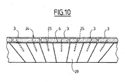
- FIG. 10 there is shown a straight-sided masonry member working in compression and including a plurality of bevel-shaped wedges 29 to ensure their mutual jamming and vault-like operation.
- Each keyway 29 is pierced with one or more blind holes in which is disposed and sealed a connector 25 projecting above the keyway 29.
- a working member 24 is installed by grouting a layer of synthetic mortar 6 above said claveaux 29, installation of prefabricated modules 3 on the layer 6, the free ends of the connectors 25 protruding into through holes provided for this purpose in the prefabricated modules 3, sealing said free ends of the connectors 25, filling spaces between the prefabricated modules 3 by a binder 7, then covering the upper surface of the prefabricated module 3 with a layer of synthetic mortar.
- a reinforcing method and a carrier structure extending between two support points and comprising a reinforcement made with materials of expansion and elasticity coefficients close to those of the material constituting the original structure, secured to said structure, at least a portion of said structure being provided with connectors capable of distributing at least a portion of the load to the reinforcing element.
- the invention is perfectly suited to any structure whose lower surface must be protected, both during the reinforcement work and at the end thereof.
Landscapes
- Engineering & Computer Science (AREA)
- Architecture (AREA)
- Civil Engineering (AREA)
- Chemical Kinetics & Catalysis (AREA)
- Electrochemistry (AREA)
- Mechanical Engineering (AREA)
- Chemical & Material Sciences (AREA)
- Structural Engineering (AREA)
- Working Measures On Existing Buildindgs (AREA)
- Forms Removed On Construction Sites Or Auxiliary Members Thereof (AREA)
- Joining Of Building Structures In Genera (AREA)
- Rod-Shaped Construction Members (AREA)
- Electrical Discharge Machining, Electrochemical Machining, And Combined Machining (AREA)
- Road Paving Structures (AREA)
- Buildings Adapted To Withstand Abnormal External Influences (AREA)
Claims (20)
- Verfahren zur Verstärkung eines Bauelements (1), das zwischen mindestens zwei Auflagern angeordnet ist und biege- oder druckbeansprucht wird, dadurch gekennzeichnet, dass mindestens auf eine Oberseite (1a) des Bauelements mehrere vorgefertigte Verstärkungsmodule (3) hinzugefügt werden, dass Verbinder (4, 5) zwischen den vorgefertigten Modulen (3) und dem Bauelement (l) angeordnet werden, und dass ein Bindemittel (6) zwischen den vorgefertigten Modulen (3) und dem Bauelement (1) angeordnet wird.
- Verfahren nach Anspruch 1, bei dem die Verbinder vor dem Hinzufügen der vorgefertigten Module (3) zum Bauelement (1) in den vorgefertigten Modulen (3) befestigt werden.
- Verfahren nach Anspruch 2, bei dem die Verbinder bei der Vorfertigung der Module in den vorgefertigten Modulen (3) befestigt werden.
- Verfahren nach Anspruch 1, bei dem die Verbinder vor dem Hinzufügen der vorgefertigten Module (3) zum Bauelement im Bauelement (1) befestigt werden.
- Verfahren nach einem der vorhergehenden Ansprüche, bei dem vor dem Hinzufügen der vorgefertigten Module zum Bauelement eine Bindemittelschicht (6) auf der Oberseite (1a) des Bauelements verteilt wird.
- Verfahren nach einem der vorhergehenden Ansprüche, bei dem Bindemittel (6) zwischen den vorgefertigten Modulen (3) verteilt wird.
- Verfahren nach einem der Ansprüche 1 bis 4, bei dem nach dem Hinzufügen der vorgefertigten Module zum Bauelement (1) Bindemittel (6) zwischen dem Bauelement (1) und den vorgefertigten Modulen (3) angeordnet wird.
- Verfahren nach einem der vorhergehenden Ansprüche, bei dem das Bauelement (1) ein Balken ist.
- Verfahren nach einem der Ansprüche 1 bis 7, bei dem das Bauelement (1) ein Gewölbe ist.
- Verfahren nach einem der vorhergehenden Ansprüche, bei dem die vorgefertigten Module (3) Beton enthalten.
- Verfahren nach Anspruch 10, bei dem die vorgefertigten Module (3) Faserbeton enthalten.
- Verfahren nach einem der vorhergehenden Ansprüche, bei dem die Verbinder (4, 5) Stangen auf der Basis von Glasfasern oder Kohlenstoff sind.
- Verfahren nach einem der Ansprüche 1 bis 11, bei dem die Verbinder (4, 5) hochfesten Stahl enthalten.
- Verfahren nach einem der vorhergehenden Ansprüche, bei dem das Bindemittel (6) einen Harzmörtel enthält.
- Verfahren nach einem der vorhergehenden Ansprüche, bei dem ein Verbinder mindestens zwei vorgefertigten Modulen (3) gemeinsam ist.
- Verfahren nach Anspruch 15, bei dem zwei vorgefertigte Module (3) sich teilweise überdecken.
- Verfahren nach einem der vorhergehenden Ansprüche, bei dem mindestens zwei vorgefertigte Module (3) mit Zähnen versehene Ränder besitzen.
- Verfahren nach einem der vorhergehenden Ansprüche, bei dem mindestens ein vorgefertigtes Modul (3) eine Unterseite besitzt, die Rauigkeiten und/oder Vertiefungen enthält.
- Verfahren nach einem der vorhergehenden Ansprüche, bei dem die vorgefertigten Module (3) in einer Schicht angeordnet sind.
- Bauelement (1), das zwischen mindestens zwei Auflagern angeordnet ist und biege- oder druckbeansprucht wird, dadurch gekennzeichnet, dass es eine Verstärkung aufweist, die auf einer Oberseite (1a) des Bauelements angeordnet und mit mehreren vorgefertigten Verstärkungsmodulen (3), Verbindern (4, 5), die die vorgefertigten Module (3) und das Bauelement verbinden, und einem Bindemittel (6) versehen ist, das zwischen den vorgefertigten Modulen und dem Bauelement angeordnet ist.
Applications Claiming Priority (2)
| Application Number | Priority Date | Filing Date | Title |
|---|---|---|---|
| FR0302495A FR2851781B1 (fr) | 2003-02-28 | 2003-02-28 | Procede de renforcement d'un element de construction et element de construction |
| FR0302495 | 2003-02-28 |
Publications (2)
| Publication Number | Publication Date |
|---|---|
| EP1452670A1 EP1452670A1 (de) | 2004-09-01 |
| EP1452670B1 true EP1452670B1 (de) | 2009-12-02 |
Family
ID=32749755
Family Applications (1)
| Application Number | Title | Priority Date | Filing Date |
|---|---|---|---|
| EP04290351A Expired - Lifetime EP1452670B1 (de) | 2003-02-28 | 2004-02-11 | Verfahren zur Verstärkung eines Bauteils und Bauteil |
Country Status (6)
| Country | Link |
|---|---|
| EP (1) | EP1452670B1 (de) |
| AT (1) | ATE450679T1 (de) |
| DE (1) | DE602004024347D1 (de) |
| ES (1) | ES2339769T3 (de) |
| FR (1) | FR2851781B1 (de) |
| PT (1) | PT1452670E (de) |
Families Citing this family (3)
| Publication number | Priority date | Publication date | Assignee | Title |
|---|---|---|---|---|
| US9249663B2 (en) * | 2009-02-27 | 2016-02-02 | Fci Holdings Delaware, Inc. | Impact resistant lagging, method for designing impact resistant lagging, and apparatus for testing impact resistant lagging |
| FR3012496B1 (fr) * | 2013-10-30 | 2016-05-20 | M Lefevre | Procede de renforcement d'un element de construction par assemblage de modules de renfort et d'au moins un element de terminaison |
| CZ305270B6 (cs) * | 2014-03-27 | 2015-07-08 | Vysoké Učení Technické V Brně | Konstrukce statického zajištění obloukové klenby pomocí prostorově uspořádané předpínací výztuže |
Family Cites Families (3)
| Publication number | Priority date | Publication date | Assignee | Title |
|---|---|---|---|---|
| GB2296276B (en) * | 1994-12-16 | 1998-07-08 | Sho Bond Corp | Method for strengthening a concrete deck |
| FR2792354B1 (fr) * | 1999-04-16 | 2007-10-12 | Lefevre Sa M | Structure de maconnerie et procede de renforcement associe |
| FR2817575B1 (fr) * | 2000-12-05 | 2003-02-21 | Lefevre Sa M | Structure de maconnerie et procede de renforcement associe |
-
2003
- 2003-02-28 FR FR0302495A patent/FR2851781B1/fr not_active Expired - Fee Related
-
2004
- 2004-02-11 EP EP04290351A patent/EP1452670B1/de not_active Expired - Lifetime
- 2004-02-11 PT PT04290351T patent/PT1452670E/pt unknown
- 2004-02-11 ES ES04290351T patent/ES2339769T3/es not_active Expired - Lifetime
- 2004-02-11 DE DE602004024347T patent/DE602004024347D1/de not_active Expired - Lifetime
- 2004-02-11 AT AT04290351T patent/ATE450679T1/de not_active IP Right Cessation
Also Published As
| Publication number | Publication date |
|---|---|
| PT1452670E (pt) | 2010-03-01 |
| EP1452670A1 (de) | 2004-09-01 |
| FR2851781A1 (fr) | 2004-09-03 |
| FR2851781B1 (fr) | 2006-04-14 |
| ES2339769T3 (es) | 2010-05-25 |
| DE602004024347D1 (de) | 2010-01-14 |
| ATE450679T1 (de) | 2009-12-15 |
Similar Documents
| Publication | Publication Date | Title |
|---|---|---|
| FR2611778A1 (fr) | Plancher a collaboration bois-beton | |
| EP3027820A1 (de) | Verfahren zum errichten einer struktur aus betonfertigteilen und entsprechende struktur | |
| EP0089861B1 (de) | Verfahren zum Verstärken von Gewölben oder ähnlichen Konstruktionen | |
| EP1045089B1 (de) | Mauerwerkstruktur und Verfahren zu deren Verstärkung | |
| EP0244890B1 (de) | Verfahren zur Herstellung von hohlen Elementen, wie etwa Leitungen, Silos oder Bunker und Elemente, hergestellt durch dieses Verfahren | |
| EP1149213B1 (de) | Platte, zusammenbau solcher platten und verwendung zum aufnehmen schwerer lasten | |
| EP4326951B1 (de) | Baustein zur errichtung eines gebäudes und verfahren zur errichtung eines gebäudes | |
| EP0717149B1 (de) | Holz-Beton Verbundkonstruktion, insbesondere für die Herstellung von Brückendecken | |
| EP1452670A1 (de) | Verfahren zur Verstärkung eines Bauteils und Bauteil | |
| EP3824151A1 (de) | Platte und fliese zur herstellung eines bodens oder einer wand und verfahren zur herstellung einer platte und fliese dieser art | |
| FR3066514B1 (fr) | Coffrage perdu isolant et procede associe pour realiser un mur. | |
| EP3293318B1 (de) | Holz-beton-verbundstrukturen | |
| FR2865490A1 (fr) | Procede et dispositif de renforcement de structure. | |
| EP2729626B1 (de) | Verfahren zur herstellung einer gründung unter verwendung einer lastverteilermatte | |
| EP3320154B1 (de) | Bauteil und herstellungsverfahren eines solchen bauelements | |
| FR2811002A1 (fr) | Procede et systeme de mise en traction d'un dispositif de renforcement de structure | |
| EP4405535B1 (de) | Mit fassadenplatten versehene konstruktion und verfahren zur herstellung einer solchen konstruktion | |
| FR2817575A1 (fr) | Structure de maconnerie et procede de renforcement associe | |
| FR2962462A1 (fr) | Panneau isolant pour l'execution de parois de batiment et son procede de fabrication | |
| EP1045091B1 (de) | Verstärkungsverfahren für Bauelement | |
| WO2025062042A1 (fr) | Procede de matage et d'agrafage (harpage) pour la reparation de fissures au sein d'un ouvrage et dispositif associe | |
| FR2885624A1 (fr) | Procede de construction d'un batiment prefabrique et element constitutif de ce batiment | |
| EP2930287B1 (de) | Herstellungsverfahren eines nicht strukturellen plattenbelags | |
| FR3163957A1 (fr) | Ensemble pour la réalisation d’une construction préfabriquée | |
| WO2022074146A1 (fr) | Système de pont modulaire et son procédé de fabrication |
Legal Events
| Date | Code | Title | Description |
|---|---|---|---|
| PUAI | Public reference made under article 153(3) epc to a published international application that has entered the european phase |
Free format text: ORIGINAL CODE: 0009012 |
|
| AK | Designated contracting states |
Kind code of ref document: A1 Designated state(s): AT BE BG CH CY CZ DE DK EE ES FI FR GB GR HU IE IT LI LU MC NL PT RO SE SI SK TR |
|
| AX | Request for extension of the european patent |
Extension state: AL HR LT LV MK |
|
| 17P | Request for examination filed |
Effective date: 20040927 |
|
| AKX | Designation fees paid |
Designated state(s): AT BE BG CH CY CZ DE DK EE ES FI FR GB GR HU IE IT LI LU MC NL PT RO SE SI SK TR |
|
| 17Q | First examination report despatched |
Effective date: 20080829 |
|
| GRAP | Despatch of communication of intention to grant a patent |
Free format text: ORIGINAL CODE: EPIDOSNIGR1 |
|
| GRAS | Grant fee paid |
Free format text: ORIGINAL CODE: EPIDOSNIGR3 |
|
| GRAA | (expected) grant |
Free format text: ORIGINAL CODE: 0009210 |
|
| AK | Designated contracting states |
Kind code of ref document: B1 Designated state(s): AT BE BG CH CY CZ DE DK EE ES FI FR GB GR HU IE IT LI LU MC NL PT RO SE SI SK TR |
|
| REG | Reference to a national code |
Ref country code: GB Ref legal event code: FG4D Free format text: NOT ENGLISH |
|
| REG | Reference to a national code |
Ref country code: CH Ref legal event code: EP |
|
| REG | Reference to a national code |
Ref country code: IE Ref legal event code: FG4D |
|
| REF | Corresponds to: |
Ref document number: 602004024347 Country of ref document: DE Date of ref document: 20100114 Kind code of ref document: P |
|
| REG | Reference to a national code |
Ref country code: PT Ref legal event code: SC4A Free format text: AVAILABILITY OF NATIONAL TRANSLATION Effective date: 20100222 |
|
| REG | Reference to a national code |
Ref country code: NL Ref legal event code: T3 |
|
| PG25 | Lapsed in a contracting state [announced via postgrant information from national office to epo] |
Ref country code: SE Free format text: LAPSE BECAUSE OF FAILURE TO SUBMIT A TRANSLATION OF THE DESCRIPTION OR TO PAY THE FEE WITHIN THE PRESCRIBED TIME-LIMIT Effective date: 20091202 Ref country code: FI Free format text: LAPSE BECAUSE OF FAILURE TO SUBMIT A TRANSLATION OF THE DESCRIPTION OR TO PAY THE FEE WITHIN THE PRESCRIBED TIME-LIMIT Effective date: 20091202 |
|
| PGFP | Annual fee paid to national office [announced via postgrant information from national office to epo] |
Ref country code: IE Payment date: 20100216 Year of fee payment: 7 |
|
| REG | Reference to a national code |
Ref country code: CH Ref legal event code: NV Representative=s name: OFFICE ERNEST T. FREYLINGER S.A. C/O SCHLUEP & DEG |
|
| REG | Reference to a national code |
Ref country code: ES Ref legal event code: FG2A Ref document number: 2339769 Country of ref document: ES Kind code of ref document: T3 |
|
| PG25 | Lapsed in a contracting state [announced via postgrant information from national office to epo] |
Ref country code: CY Free format text: LAPSE BECAUSE OF FAILURE TO SUBMIT A TRANSLATION OF THE DESCRIPTION OR TO PAY THE FEE WITHIN THE PRESCRIBED TIME-LIMIT Effective date: 20091202 Ref country code: SI Free format text: LAPSE BECAUSE OF FAILURE TO SUBMIT A TRANSLATION OF THE DESCRIPTION OR TO PAY THE FEE WITHIN THE PRESCRIBED TIME-LIMIT Effective date: 20091202 |
|
| PGFP | Annual fee paid to national office [announced via postgrant information from national office to epo] |
Ref country code: AT Payment date: 20100218 Year of fee payment: 7 |
|
| PG25 | Lapsed in a contracting state [announced via postgrant information from national office to epo] |
Ref country code: BG Free format text: LAPSE BECAUSE OF FAILURE TO SUBMIT A TRANSLATION OF THE DESCRIPTION OR TO PAY THE FEE WITHIN THE PRESCRIBED TIME-LIMIT Effective date: 20100302 Ref country code: EE Free format text: LAPSE BECAUSE OF FAILURE TO SUBMIT A TRANSLATION OF THE DESCRIPTION OR TO PAY THE FEE WITHIN THE PRESCRIBED TIME-LIMIT Effective date: 20091202 Ref country code: RO Free format text: LAPSE BECAUSE OF FAILURE TO SUBMIT A TRANSLATION OF THE DESCRIPTION OR TO PAY THE FEE WITHIN THE PRESCRIBED TIME-LIMIT Effective date: 20091202 |
|
| PG25 | Lapsed in a contracting state [announced via postgrant information from national office to epo] |
Ref country code: SK Free format text: LAPSE BECAUSE OF FAILURE TO SUBMIT A TRANSLATION OF THE DESCRIPTION OR TO PAY THE FEE WITHIN THE PRESCRIBED TIME-LIMIT Effective date: 20091202 Ref country code: CZ Free format text: LAPSE BECAUSE OF FAILURE TO SUBMIT A TRANSLATION OF THE DESCRIPTION OR TO PAY THE FEE WITHIN THE PRESCRIBED TIME-LIMIT Effective date: 20091202 |
|
| PLBE | No opposition filed within time limit |
Free format text: ORIGINAL CODE: 0009261 |
|
| STAA | Information on the status of an ep patent application or granted ep patent |
Free format text: STATUS: NO OPPOSITION FILED WITHIN TIME LIMIT |
|
| PG25 | Lapsed in a contracting state [announced via postgrant information from national office to epo] |
Ref country code: GR Free format text: LAPSE BECAUSE OF FAILURE TO SUBMIT A TRANSLATION OF THE DESCRIPTION OR TO PAY THE FEE WITHIN THE PRESCRIBED TIME-LIMIT Effective date: 20100303 |
|
| 26N | No opposition filed |
Effective date: 20100903 |
|
| PG25 | Lapsed in a contracting state [announced via postgrant information from national office to epo] |
Ref country code: DK Free format text: LAPSE BECAUSE OF FAILURE TO SUBMIT A TRANSLATION OF THE DESCRIPTION OR TO PAY THE FEE WITHIN THE PRESCRIBED TIME-LIMIT Effective date: 20091202 |
|
| PGFP | Annual fee paid to national office [announced via postgrant information from national office to epo] |
Ref country code: LU Payment date: 20110120 Year of fee payment: 8 |
|
| REG | Reference to a national code |
Ref country code: IE Ref legal event code: MM4A |
|
| PG25 | Lapsed in a contracting state [announced via postgrant information from national office to epo] |
Ref country code: AT Free format text: LAPSE BECAUSE OF NON-PAYMENT OF DUE FEES Effective date: 20110211 |
|
| PG25 | Lapsed in a contracting state [announced via postgrant information from national office to epo] |
Ref country code: IE Free format text: LAPSE BECAUSE OF NON-PAYMENT OF DUE FEES Effective date: 20110211 |
|
| PGFP | Annual fee paid to national office [announced via postgrant information from national office to epo] |
Ref country code: PT Payment date: 20111207 Year of fee payment: 9 |
|
| PGFP | Annual fee paid to national office [announced via postgrant information from national office to epo] |
Ref country code: CH Payment date: 20120321 Year of fee payment: 9 Ref country code: MC Payment date: 20120118 Year of fee payment: 9 |
|
| PGFP | Annual fee paid to national office [announced via postgrant information from national office to epo] |
Ref country code: GB Payment date: 20120217 Year of fee payment: 9 Ref country code: IT Payment date: 20120222 Year of fee payment: 9 Ref country code: BE Payment date: 20120224 Year of fee payment: 9 |
|
| PGFP | Annual fee paid to national office [announced via postgrant information from national office to epo] |
Ref country code: NL Payment date: 20120125 Year of fee payment: 9 Ref country code: DE Payment date: 20120320 Year of fee payment: 9 |
|
| PG25 | Lapsed in a contracting state [announced via postgrant information from national office to epo] |
Ref country code: HU Free format text: LAPSE BECAUSE OF FAILURE TO SUBMIT A TRANSLATION OF THE DESCRIPTION OR TO PAY THE FEE WITHIN THE PRESCRIBED TIME-LIMIT Effective date: 20100603 |
|
| PG25 | Lapsed in a contracting state [announced via postgrant information from national office to epo] |
Ref country code: TR Free format text: LAPSE BECAUSE OF FAILURE TO SUBMIT A TRANSLATION OF THE DESCRIPTION OR TO PAY THE FEE WITHIN THE PRESCRIBED TIME-LIMIT Effective date: 20091202 |
|
| PGFP | Annual fee paid to national office [announced via postgrant information from national office to epo] |
Ref country code: ES Payment date: 20120224 Year of fee payment: 9 |
|
| REG | Reference to a national code |
Ref country code: PT Ref legal event code: MM4A Free format text: LAPSE DUE TO NON-PAYMENT OF FEES Effective date: 20130812 |
|
| BERE | Be: lapsed |
Owner name: M. LEFEVRE S.A. Effective date: 20130228 |
|
| REG | Reference to a national code |
Ref country code: NL Ref legal event code: V1 Effective date: 20130901 |
|
| PG25 | Lapsed in a contracting state [announced via postgrant information from national office to epo] |
Ref country code: MC Free format text: LAPSE BECAUSE OF NON-PAYMENT OF DUE FEES Effective date: 20130228 |
|
| REG | Reference to a national code |
Ref country code: CH Ref legal event code: PL |
|
| GBPC | Gb: european patent ceased through non-payment of renewal fee |
Effective date: 20130211 |
|
| PG25 | Lapsed in a contracting state [announced via postgrant information from national office to epo] |
Ref country code: LI Free format text: LAPSE BECAUSE OF NON-PAYMENT OF DUE FEES Effective date: 20130228 Ref country code: NL Free format text: LAPSE BECAUSE OF NON-PAYMENT OF DUE FEES Effective date: 20130901 Ref country code: PT Free format text: LAPSE BECAUSE OF NON-PAYMENT OF DUE FEES Effective date: 20130812 Ref country code: CH Free format text: LAPSE BECAUSE OF NON-PAYMENT OF DUE FEES Effective date: 20130228 |
|
| REG | Reference to a national code |
Ref country code: DE Ref legal event code: R119 Ref document number: 602004024347 Country of ref document: DE Effective date: 20130903 |
|
| PG25 | Lapsed in a contracting state [announced via postgrant information from national office to epo] |
Ref country code: IT Free format text: LAPSE BECAUSE OF NON-PAYMENT OF DUE FEES Effective date: 20130211 |
|
| PG25 | Lapsed in a contracting state [announced via postgrant information from national office to epo] |
Ref country code: DE Free format text: LAPSE BECAUSE OF NON-PAYMENT OF DUE FEES Effective date: 20130903 Ref country code: BE Free format text: LAPSE BECAUSE OF NON-PAYMENT OF DUE FEES Effective date: 20130228 Ref country code: GB Free format text: LAPSE BECAUSE OF NON-PAYMENT OF DUE FEES Effective date: 20130211 |
|
| REG | Reference to a national code |
Ref country code: ES Ref legal event code: FD2A Effective date: 20140611 |
|
| PG25 | Lapsed in a contracting state [announced via postgrant information from national office to epo] |
Ref country code: ES Free format text: LAPSE BECAUSE OF NON-PAYMENT OF DUE FEES Effective date: 20130212 |
|
| PG25 | Lapsed in a contracting state [announced via postgrant information from national office to epo] |
Ref country code: LU Free format text: LAPSE BECAUSE OF NON-PAYMENT OF DUE FEES Effective date: 20130211 |
|
| REG | Reference to a national code |
Ref country code: FR Ref legal event code: PLFP Year of fee payment: 13 |
|
| PGFP | Annual fee paid to national office [announced via postgrant information from national office to epo] |
Ref country code: FR Payment date: 20160226 Year of fee payment: 13 |
|
| REG | Reference to a national code |
Ref country code: FR Ref legal event code: ST Effective date: 20171031 |
|
| PG25 | Lapsed in a contracting state [announced via postgrant information from national office to epo] |
Ref country code: FR Free format text: LAPSE BECAUSE OF NON-PAYMENT OF DUE FEES Effective date: 20170228 |