EP1452707A1 - Dispositif de protection d'une structure d entree d'air d'un moteur a reaction - Google Patents
Dispositif de protection d'une structure d entree d'air d'un moteur a reaction Download PDFInfo
- Publication number
- EP1452707A1 EP1452707A1 EP04100755A EP04100755A EP1452707A1 EP 1452707 A1 EP1452707 A1 EP 1452707A1 EP 04100755 A EP04100755 A EP 04100755A EP 04100755 A EP04100755 A EP 04100755A EP 1452707 A1 EP1452707 A1 EP 1452707A1
- Authority
- EP
- European Patent Office
- Prior art keywords
- cover
- air intake
- protective
- engine
- protective device
- Prior art date
- Legal status (The legal status is an assumption and is not a legal conclusion. Google has not performed a legal analysis and makes no representation as to the accuracy of the status listed.)
- Granted
Links
- 230000001681 protective effect Effects 0.000 title claims description 43
- 238000009423 ventilation Methods 0.000 claims abstract description 38
- 239000004744 fabric Substances 0.000 claims description 6
- 235000021183 entrée Nutrition 0.000 description 2
- 230000009931 harmful effect Effects 0.000 description 2
- 239000003973 paint Substances 0.000 description 2
- 238000007747 plating Methods 0.000 description 2
- 238000006748 scratching Methods 0.000 description 2
- 230000002393 scratching effect Effects 0.000 description 2
- XLYOFNOQVPJJNP-UHFFFAOYSA-N water Substances O XLYOFNOQVPJJNP-UHFFFAOYSA-N 0.000 description 2
- 239000003082 abrasive agent Substances 0.000 description 1
- 230000000903 blocking effect Effects 0.000 description 1
- 230000015556 catabolic process Effects 0.000 description 1
- 230000000295 complement effect Effects 0.000 description 1
- 238000009434 installation Methods 0.000 description 1
- 238000012986 modification Methods 0.000 description 1
- 230000004048 modification Effects 0.000 description 1
- 230000002035 prolonged effect Effects 0.000 description 1
- 238000012552 review Methods 0.000 description 1
- 238000007789 sealing Methods 0.000 description 1
- 238000010257 thawing Methods 0.000 description 1
Images

Classifications
-
- B—PERFORMING OPERATIONS; TRANSPORTING
- B64—AIRCRAFT; AVIATION; COSMONAUTICS
- B64F—GROUND OR AIRCRAFT-CARRIER-DECK INSTALLATIONS SPECIALLY ADAPTED FOR USE IN CONNECTION WITH AIRCRAFT; DESIGNING, MANUFACTURING, ASSEMBLING, CLEANING, MAINTAINING OR REPAIRING AIRCRAFT, NOT OTHERWISE PROVIDED FOR; HANDLING, TRANSPORTING, TESTING OR INSPECTING AIRCRAFT COMPONENTS, NOT OTHERWISE PROVIDED FOR
- B64F1/00—Ground or aircraft-carrier-deck installations
- B64F1/005—Protective coverings for aircraft not in use
-
- F—MECHANICAL ENGINEERING; LIGHTING; HEATING; WEAPONS; BLASTING
- F02—COMBUSTION ENGINES; HOT-GAS OR COMBUSTION-PRODUCT ENGINE PLANTS
- F02C—GAS-TURBINE PLANTS; AIR INTAKES FOR JET-PROPULSION PLANTS; CONTROLLING FUEL SUPPLY IN AIR-BREATHING JET-PROPULSION PLANTS
- F02C7/00—Features, components parts, details or accessories, not provided for in, or of interest apart form groups F02C1/00 - F02C6/00; Air intakes for jet-propulsion plants
- F02C7/04—Air intakes for gas-turbine plants or jet-propulsion plants
-
- Y—GENERAL TAGGING OF NEW TECHNOLOGICAL DEVELOPMENTS; GENERAL TAGGING OF CROSS-SECTIONAL TECHNOLOGIES SPANNING OVER SEVERAL SECTIONS OF THE IPC; TECHNICAL SUBJECTS COVERED BY FORMER USPC CROSS-REFERENCE ART COLLECTIONS [XRACs] AND DIGESTS
- Y02—TECHNOLOGIES OR APPLICATIONS FOR MITIGATION OR ADAPTATION AGAINST CLIMATE CHANGE
- Y02T—CLIMATE CHANGE MITIGATION TECHNOLOGIES RELATED TO TRANSPORTATION
- Y02T50/00—Aeronautics or air transport
- Y02T50/60—Efficient propulsion technologies, e.g. for aircraft
Definitions
- the present invention relates so general in the field of structure protection air intake of a jet engine fitted to a aircraft.
- This protection is intended in particular to be assembled on the engine during the storage phases extended from the aircraft, to prevent access to inside the engine.
- FIG. 1 it is depicted a conventional jet engine 1 intended for be mounted on a wing of an aircraft (not shown), via a mast 2 secured to a nacelle 4 of this jet engine.
- an air intake structure 6, composed of a air inlet cover 8, extended by an inlet lip air 10.
- cover 8 and the lip 10 jointly and externally delimit a channel of annular blower 12, of which an inlet 14 is defined by lip 10.
- a tarpaulin is provided. protection 16 able to be assembled on the structure air inlet 6, so as to cover all of entrance 14 of channel 12.
- the tarpaulin protection 16 is substantially disc-shaped and provided with circumferentially spaced fasteners 18, these fasteners 18 being capable of cooperating with complementary fasteners (not shown), arranged also circumferentially around the hood air inlet 8 near the junction with the lip 10. Note that the assembly of this tarpaulin protection 16 on the air intake structure 6 is carried out using a lifting platform, less necessary to hang tarpaulin 16 on the upper portion of the structure 6.
- the air inlet cover 8 includes a ventilation scoop 20 of a ventilation (not shown), the latter circulating in the air intake structure 6 of the engine 1.
- the ventilation scoop 20, placed on the upper portion of the air intake cover 8, must therefore also be closed during the storage phases extended from the aircraft, so that various objects, water or birds are not able to enter the interior of the ventilation duct.
- the bailer of ventilation 20 is at a relatively distant distant from the end of the air intake lip 10, this distance is usually at least equal to 1.50 m. Therefore, to carry out the operation assembly of the plug 22 on the ventilation scoop 20, an operator located on the platform lift must practically lie entirely on the upper portion of the air intake cover 8.
- the operator in front must lie on the entrance structure air 6, it can unexpectedly cause a scratch damage to the outer surface of this structure, for example by friction of its belt on the cover 8 and lip 10 paint.
- air inlet cover 8 has a withdrawal zone 24 in which is located one or more exhaust ports (not shown) a hot air line (not shown), the latter used for defrosting the air intake structure 6 of engine 1.
- the invention therefore aims to provide a protection device for an air intake structure of a jet engine, the device remedying the less partially to the disadvantages mentioned above relating to the achievements of the prior art.
- the invention relates to a protection device for an air intake structure of a jet engine, the structure comprising a air intake cover and an air intake lip jointly defining with the hood a channel of blower, the hood having an upper portion fitted with at least one ventilation scoop and the lip defining an inlet to the blower channel, the device comprising a protective cover having a main portion made so as to seal the inlet of the blower channel when the device is assembled on the air intake structure of the engine.
- the protective cover comprises also a secondary portion integral with the main portion, this secondary portion being provided with stiffening means and intended for partially cover the air inlet cover of the motor, to close each ventilation scoop.
- the secondary portion of the protective cover is substantially stiffened by the stiffening means, which allows it to present and keep a pre-established, adapted form to marry the upper portion of the air inlet cover on which the bailer is located ventilation. So when the secondary portion of the tarpaulin is correctly positioned on the upper portion of the air intake cover, covered ventilation is condemned and prohibited by therefore any intrusion into the conduct of ventilation.
- an operator being located on the lifting platform can thus easily discard the rigid secondary portion so that it covers the part of the hood fitted with the scoop ventilation, for example after the operator has proceeded to a classic assembly of the portion main of this tarpaulin, in order to protect the inlet of the blower channel.
- the means of stiffening equipping the secondary portion of the tarpaulin extend into the part main of this tarpaulin.
- the direct consequence of a such arrangement is that the junction between the portion main and the secondary portion of the tarpaulin protection is substantially rigid. In this way, when the main portion is assembled and the secondary portion of the tarpaulin is launched on the air intake hood, this is still more assured of occupying an adequate position on that same hood.
- the means of stiffening include a plurality of lamellae rigid preformed with respect to the curve of the structure engine air intake, so that the tarpaulin device protection follows this structure of the as best as possible, and that the risks of intrusion any elements in the ventilation duct are almost zero.
- the rigid lamellae are preferably arranged so that the portion secondary cover is foldable, this characteristic making it possible in particular to reduce considerably the size of the device protection to be stored in the dog compartment of the aircraft.
- the rigid slats are also arranged so that when the device is assembled on the engine air intake structure, they form rows substantially parallel to a main longitudinal axis of this engine.
- the rows can each be made up several rigid strips arranged in the extension of each other, parts of the protective cover located between two slats directly consecutive can then advantageously serve as a folding area.
- the rigid slats of preferably metallic, can be incorporated into the protective cover for the device, this cover being preferably made of fabric.
- the device protection so configured does not cause damage, including scratching, of the surface exterior of the engine air intake structure.
- the main portion of the protective cover is substantially in the form of disc and the secondary portion of this tarp is substantially band-like, one end of the secondary portion being connected to the portion main at a circumference of this last.
- the tarpaulin can be designed so that when the device is assembled on the engine air intake structure, the circumference of the main portion of the tarpaulin protection is located near a junction between the air inlet cover and the air inlet lip of the engine air intake structure.
- the protective device can by elsewhere have straps for fixing the secondary portion, the straps being connected to the other end of the secondary portion, and likely to surround the air inlet cover of the engine air intake structure. So these straps advantageously allow to counter the harmful effects what could the wind cause on the portion tarpaulin secondary, such as an uplift of this last authorizing the intrusion of elements into inside the ventilation duct.
- the protective cover also includes a portion tertiary in solidarity with the main portion, the tertiary portion being provided with means of stiffening and intended to partially cover the engine air intake hood to seal each exhaust port belonging to an air duct hot and being provided on a lower portion of the air inlet cover.
- the device no longer requires a storage case, so that the constraints of mass and size relating to the presence of this type of suitcase and encountered in the prior art no longer exist.
- the device solely made up of the protective cover and various fixing means likely to ensure its assembly on the structure engine air intake, advantageously takes the form of a single piece easily able to be folded, then directly placed in the dog's hold the aircraft.
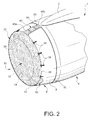
- FIG 2 we see a air intake structure 6 of a jet engine conventional 1, intended to be mounted on an aircraft (not shown) by means of an integral mast 2 an engine nacelle 4, the latter being substantially identical to that shown in the figure 1 and described above.
- the air intake structure 6 is located at the front of nacelle 4 is composed of a air inlet cover 8, fitted with a ventilation scoop 20 on its upper portion, this scoop 20 belonging to a ventilation duct (not shown). It is specified that usually the scoop of ventilation 20 is located at the level of the part higher of the air inlet cover 8, substantially in extension of the mast 2.
- the cover 8 also includes one or more exhaust ports (not shown in Figure 2) belonging to a pipe hot air (not shown), these orifices exhaust being provided on a lower portion the air inlet cover 8.
- the air intake structure 6 comprises at in addition to an air intake lip 10, arranged in the extension of the cover 8, the purpose of this lip 10 being ensure air sharing between the party that gets inside engine 1 and the part that flows around the nacelle 4.
- the air intake cover 8 and the air inlet lip 10 jointly delimit and externally an annular blower channel 12, an entry 14 of which is defined by lip 10.
- protection device 30 according to a mode preferred embodiment of the present invention.
- This device 30 can in particular be assembled on the air intake structure 6 during the prolonged storage of the aircraft, to avoid intrusion of any elements inside the motor 1, through the ventilation scoop 20, the orifices or the inlet 14 of the blower 12.
- the protective device 30 is essentially fitted with a protective cover 32, preferably fabric, a main portion 34 of which is able to close the inlet 14 of the fan channel 12.
- This main portion 34 takes preferably in the form of a disc, one of which annular end portion is provided with fasteners 36 circumferentially arranged, these fasteners 36 forming an integral part of the device 30 and being arranged so as to be able to cooperate with additional fasteners 38, also provided circumferentially around the air inlet cover 8, near the junction with the lip 10.
- the portion main disc-shaped 34 is noticeably taut and its circumference 39 is close of the junction between the air inlet cover 8 and the air inlet lip 10. In this way, the obturation provoked safely prohibits intrusion objects inside the blower channel 12 of the motor 1.
- the protective cover 32 includes a secondary portion 40, integral with the main portion 34.
- the secondary portion 40 preferably in the form of a strip, is intended for partially cover the upper portion of the cover air inlet 8, so as to close the scoop of breakdown 20, and therefore prohibit intrusion of objects, birds or water inside of the ventilation duct.
- the secondary portion 40 in the form of a strip has a first end 40a connected to the portion main 34 at the circumference 39 of this last, as well as a second end 40b designed so as to extend beyond the ventilation scoop 20, when the main 34 and secondary 40 portions are assembled on structure 6.
- the secondary portion 40 of the tarpaulin protection 32 is provided with stiffening means 42, these allowing the plating of this portion 40 against the air inlet cover 8.
- the stiffening means 42 make it possible to stiffen the tissue of the portion 40 so that it adopts a given configuration, provided for that once launched on structure 6, at least one much of secondary portion 40 wife hood 8 correctly and therefore prohibited access to the ventilation scoop 20.
- the stiffening means 42 are composed of a plurality of rigid lamellae 44, preferably metallic and preformed to the curve of the structure air inlet 6.
- the secondary portion 40 of the cover 32 is able to marry very precisely the cover 8, in particular thanks to the weight of the rigid strips 44, which generates a plating satisfying fabric against the outer surface of this cover 8.
- the rigid lamellae 44 are not only provided to equip the secondary portion 40 from cover 32, but also extend into the annular end portion of the portion main 34, which is intended to be in contact with the air intake lip 10 when the protection 30 is assembled on structure 6.
- the portion of the portion end cap fitted with rigid lamellae 44 as well as the first end 40a of the portion secondary 40 together form an area substantially rigid. Therefore, when the main portion 34 of the cover 32 is effectively assembled on the structure 6 of motor 1, this portion 34 stretched by the fasteners 36 and 38 induce an imposed positioning for the annular end portion, and therefore also an imposed positioning for the end 40a substantially rigidly connected to the end portion annular. Of course, these imposed positions are adapted so that when the secondary portion 40 is launched on the cover 8, it correctly matches the outer surface of it.
- the rigid lamellae 44 are in the form of two rows 46a and 46b extending in a direction substantially parallel to a longitudinal main axis (not shown) of the motor 1, when the device 30 is assembled on the air intake structure 6.
- the number and the positioning of the rows can be adapted by depending on the conditions encountered, without leaving the part of the invention.
- each of the two rows 46a and 46b has a plurality of lamellae rigid 44 arranged in the extension of one of the other.
- these different lamellae 44 it is possible to arrange these different lamellae 44 so as to obtain zones folding 48 of the secondary portion 40, these areas of folding 48 corresponding to fabric strips extending substantially perpendicular to the direction of rows 46a and 46b, and therefore substantially perpendicular to the main longitudinal axis of the motor 1.
- the operator will just have to make sure that the secondary portion 40 has completely to be certain that it covers structure 6 and the ventilation scoop correctly 20.
- the secondary portion 40 occurs in the form of a non-foldable rigid portion, without depart from the scope of the invention.
- the protective device 30 may include straps fixing 50 of this secondary portion 40.
- These straps 50 preferably made in a non-abrasive material so as not to scratch the paint of the outer surface of the cover 8, are integral with the second end 40b of the portion 40, and intended surround the nacelle 4 before being connected between they.
- fixing straps 50 are preferably fixed on or near the part of the secondary portion 40 intended to cover the scoop of ventilation 20, so that any intrusion into the ventilation duct is definitely avoided.
- the protective cover 32 comprises also a tertiary portion 52, integral with the main portion 34.
- the tertiary portion 52 preferably in the form of a half-disc, is intended to partially cover the portion bottom of the air inlet cover 8, so that close each exhaust port 54, and prohibit therefore the intrusion of objects or birds into inside the hot air duct.
- this tertiary portion 52 is designed according to a principle similar to that of secondary portion 40, with the difference that it is not foldable. Indeed, the withdrawal zone 24 in which is located the plurality of exhaust ports 54 is able to be automatically covered by the portion tertiary 52, when the main portion 34 is assembled on the structure 6.
- stiffening means 56 taking preferably also the form of a plurality of rigid strips 58, preformed to the curve of the structure 6 and each extending into the annular end portion of the main portion 34.
- protection device 30 which has just been described, only by way of nonlimiting example.
Landscapes
- Engineering & Computer Science (AREA)
- Combustion & Propulsion (AREA)
- Chemical & Material Sciences (AREA)
- Mechanical Engineering (AREA)
- General Engineering & Computer Science (AREA)
- Aviation & Aerospace Engineering (AREA)
- Cooling, Air Intake And Gas Exhaust, And Fuel Tank Arrangements In Propulsion Units (AREA)
- Superstructure Of Vehicle (AREA)
- Exhaust Gas After Treatment (AREA)
- Lubrication Details And Ventilation Of Internal Combustion Engines (AREA)
- Cylinder Crankcases Of Internal Combustion Engines (AREA)
- Exhaust Silencers (AREA)
- Motor Or Generator Cooling System (AREA)
- Structures Of Non-Positive Displacement Pumps (AREA)
Abstract
Description
- la figure 1, déjà décrite, représente une vue partiellement éclatée en perspective d'un moteur à réaction d'un aéronef équipé de moyens de protection classiques de la structure d'entrée d'air de ce moteur,
- la figure 2 représente une vue partielle en perspective du moteur représenté sur la figure 1, un dispositif de protection selon un mode de réalisation préféré de la présente invention étant assemblé sur la structure d'entrée d'air de ce moteur,
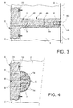
- la figure 3 représente une vue partielle de dessus de la figure 2, et
- la figure 4 représente une vue partielle de dessous de la figure 2.
Claims (11)
- Dispositif de protection (30) d'une structure d'entrée d'air (6) d'un moteur à réaction (1), ladite structure (6) comportant un capot d'entrée d'air (8) ainsi qu'une lèvre d'entrée d'air (10) délimitant conjointement avec ledit capot (8) un canal de soufflante (12), le capot (8) disposant d'une portion supérieure munie d'au moins une écope de ventilation (20) et la lèvre (10) définissant une entrée (14) du canal de soufflante (12), le dispositif (30) comprenant une bâche de protection (32) disposant d'une portion principale (34) réalisée de manière à obturer l'entrée (14) du canal de soufflante (12) lorsque le dispositif (30) est assemblé sur la structure d'entrée d'air (6) du moteur (1), caractérisé en ce que la bâche de protection (32) comporte également une portion secondaire (40) solidaire de la portion principale (34), ladite portion secondaire (40) étant munie de moyens de rigidification (42) et destinée à recouvrir partiellement le capot d'entrée d'air (8) du moteur (1), afin d'obturer chaque écope de ventilation (20).
- Dispositif de protection (30) selon la revendication 1, caractérisé en ce que les moyens de rigidification (42) équipant la portion secondaire (40) de la bâche de protection (32) se prolongent dans la partie principale (34) de ladite bâche (32).
- Dispositif de protection (30) selon la revendication 1 ou la revendication 2, caractérisé en ce que les moyens de rigidification (42) comprennent une pluralité de lamelles rigides (44) préformées par rapport au galbe de la structure d'entrée d'air (6) du moteur (1).
- Dispositif de protection (30) selon la revendication 3, caractérisé en ce que les lamelles rigides (44) sont agencées de sorte que la portion secondaire (40) de la bâche de protection (32) soit pliable.
- Dispositif de protection (30) selon la revendication 3 ou la revendication 4, caractérisé en ce que les lamelles rigides (44) sont agencées de sorte que lorsque le dispositif (30) est assemblé sur la structure d'entrée d'air (6) du moteur (1), elles forment des rangées (46a,46b) sensiblement parallèles à un axe principal longitudinal de ce moteur (1).
- Dispositif de protection (30) selon l'une quelconque des revendications 3 à 5, caractérisé en ce que les lamelles rigides (44) sont incorporées à la bâche de protection (32) du dispositif (30).
- Dispositif de protection (30) selon l'une quelconque des revendications 3 à 6, caractérisé en ce que la bâche de protection (32) est en tissu, et en ce que les lamelles rigides (44) sont métalliques.
- Dispositif de protection (30) selon l'une quelconque des revendications précédentes, caractérisé en ce que la portion principale (34) de la bâche de protection (32) est sensiblement en forme de disque et en ce que la portion secondaire (40) de cette bâche (32) est sensiblement en forme de bande, une extrémité (40a) de ladite portion secondaire (40) étant raccordée à ladite portion principale (34) au niveau d'une circonférence (39) de cette dernière.
- Dispositif de protection (30) selon la revendication 8, caractérisé en ce que la bâche de protection (32) est conçue de sorte que lorsque le dispositif (30) est assemblé sur la structure d'entrée d'air (6) du moteur (1), la circonférence (39) de la portion principale (34) de la bâche de protection (32) se situe à proximité d'une jonction entre le capot d'entrée d'air (8) et la lèvre d'entrée d'air (10) de la structure d'entrée d'air (6) du moteur (1).
- Dispositif de protection (30) selon la revendication 8 ou la revendication 9, caractérisé en ce que le dispositif (30) comporte en outre des sangles de fixation (50) de ladite portion secondaire (40), lesdites sangles (50) étant raccordées à l'autre extrémité (40b) de ladite portion secondaire (40), et susceptibles d'entourer le capot d'entrée d'air (8) de la structure d'entrée d'air (6) du moteur (1).
- Dispositif de protection (30) selon l'une quelconque des revendications précédentes, caractérisé en ce que la bâche de protection (32) comporte en outre une portion tertiaire (52) solidaire de la portion principale (34), ladite portion tertiaire (52) étant munie de moyens de rigidification (56) et destinée à recouvrir partiellement le capot d'entrée d'air (8) du moteur (1), afin d'obturer chaque orifice d'échappement (54) appartenant à une conduite d'air chaud et étant prévu sur une portion inférieure du capot d'entrée d'air (8).
Applications Claiming Priority (2)
| Application Number | Priority Date | Filing Date | Title |
|---|---|---|---|
| FR0302459 | 2003-02-28 | ||
| FR0302459A FR2851787B1 (fr) | 2003-02-28 | 2003-02-28 | Dispositif de protection d'une structure d'entree d'air d'un moteur a reaction |
Publications (2)
| Publication Number | Publication Date |
|---|---|
| EP1452707A1 true EP1452707A1 (fr) | 2004-09-01 |
| EP1452707B1 EP1452707B1 (fr) | 2005-11-16 |
Family
ID=32749747
Family Applications (1)
| Application Number | Title | Priority Date | Filing Date |
|---|---|---|---|
| EP04100755A Expired - Lifetime EP1452707B1 (fr) | 2003-02-28 | 2004-02-26 | Dispositif de protection d'une structure d entree d'air d'un moteur a reaction |
Country Status (6)
| Country | Link |
|---|---|
| US (1) | US6871819B2 (fr) |
| EP (1) | EP1452707B1 (fr) |
| AT (1) | ATE310158T1 (fr) |
| CA (1) | CA2458434C (fr) |
| DE (1) | DE602004000180T2 (fr) |
| FR (1) | FR2851787B1 (fr) |
Cited By (3)
| Publication number | Priority date | Publication date | Assignee | Title |
|---|---|---|---|---|
| EP2075436A3 (fr) * | 2007-12-28 | 2009-07-08 | General Electric Company | Cône d'entrée pour une turbine à gaz |
| EP2075420A3 (fr) * | 2007-12-28 | 2009-07-29 | General Electric Company | Procédé de préparation d'un moteur pour le transport |
| CN111846251A (zh) * | 2020-07-10 | 2020-10-30 | 山东太古飞机工程有限公司 | 一种用于发动机进气口、排气及尾喷嘴的防沙保护装置 |
Families Citing this family (28)
| Publication number | Priority date | Publication date | Assignee | Title |
|---|---|---|---|---|
| US8613591B2 (en) * | 2006-09-07 | 2013-12-24 | Pratt & Whitney Canada Corp. | Fan case abradable drainage trench and slot |
| US20090101760A1 (en) * | 2007-03-26 | 2009-04-23 | Maahnchooh Donald Mundingo Ghogomu | Aircraft engine protection unit (A.E.P.U) |
| USD614560S1 (en) | 2009-02-25 | 2010-04-27 | Alexander Charles R | Foreign object deflector |
| US20100284791A1 (en) * | 2009-05-11 | 2010-11-11 | Robert Jesse Flores | Apparatuses, systems, and methods for preventing foreign objects from being ingested into a jet engine |
| US7871455B1 (en) * | 2009-06-19 | 2011-01-18 | Vintage Capital Group, Llc | Jet engine protection system |
| US20100326040A1 (en) * | 2009-06-30 | 2010-12-30 | Robert Alfred | Bird and debris guand for a jet engine |
| US8052083B1 (en) * | 2009-09-17 | 2011-11-08 | John Patrick Moran | Bird deflector and air replacement system technical field |
| US7803204B1 (en) * | 2009-10-19 | 2010-09-28 | Mladinich Julius C | Foreign object deflector for jet engine |
| USD621852S1 (en) * | 2010-01-26 | 2010-08-17 | John Zunik | Aircraft engine safety shield |
| DE202012100112U1 (de) * | 2012-01-12 | 2012-02-27 | Klaus Rinck | Abdeckplane für Flugzeugtriebwerke |
| US8651415B1 (en) * | 2012-02-08 | 2014-02-18 | The Boeing Company | Engine cowl and inlet cover |
| US9446857B2 (en) * | 2012-02-08 | 2016-09-20 | The Boeing Company | Engine cowl and inlet cover |
| US8950701B2 (en) | 2012-02-08 | 2015-02-10 | The Boeing Company | Engine cowl and inlet cover |
| US8777154B2 (en) * | 2012-07-09 | 2014-07-15 | United Technologies Corporation | Apparatus and method for preventing gas turbine engine freezing |
| FR2998620B1 (fr) * | 2012-11-29 | 2018-04-06 | Safran Aircraft Engines | Capot de turbomachine apte a recouvrir un cone de soufflante |
| DE102014222754A1 (de) * | 2014-11-07 | 2016-05-12 | Siemens Aktiengesellschaft | Abdichtvorrichtung zum Abdichten eines Kanals einer Gasturbine zur Vermeidung von Stillstandkorrosion |
| US9550581B2 (en) | 2015-02-26 | 2017-01-24 | Pratt & Whitney Canada Corp. | Gas turbine engine cover |
| CN106864759A (zh) * | 2017-02-20 | 2017-06-20 | 张延林 | 飞机发动机防护装置及防护方法 |
| DE102018206650A1 (de) * | 2018-04-30 | 2019-10-31 | MTU Aero Engines AG | Abdeckung für eine Triebwerksgondel |
| CN108941144A (zh) * | 2018-09-12 | 2018-12-07 | 上海电气核电设备有限公司 | 适用于大直径钢制开口筒体的防尘罩及其安装方法 |
| DE102019200939B4 (de) * | 2019-01-25 | 2020-12-10 | Lufthansa Technik Aktiengesellschaft | Abdeckung für Flugzeugtriebwerke |
| CN111169652A (zh) * | 2019-11-15 | 2020-05-19 | 陕西飞机工业(集团)有限公司 | 一种发动机尾喷口防护设备 |
| US12234034B2 (en) * | 2021-06-29 | 2025-02-25 | Serias-Lee, Llc | Aircraft opening plug and installation tool |
| FR3126925B1 (fr) * | 2021-09-10 | 2025-04-18 | Airbus Operations Sas | Bâche de protection pour moteur de propulsion d’aéronef. |
| CA3183793A1 (fr) | 2022-12-12 | 2024-06-12 | Protech Engine Solutions | Couvercle de protection pour moteurs d~aeronef |
| US20250122814A1 (en) * | 2023-10-16 | 2025-04-17 | Serias-Lee, Llc | Aircraft Engine Opening Shield System with Installation Tool |
| EP4574680A1 (fr) * | 2023-12-19 | 2025-06-25 | Airbus Operations GmbH | Dispositif de capot de protection de moteur pour assurer l'étanchéité à l'air d'un moteur d'un aéronef ou d'un engin spatial |
| US12454368B1 (en) * | 2024-08-26 | 2025-10-28 | Glenn Thomas Labay | Protective cover for foreign object damage prevention and aircraft parts protection |
Citations (6)
| Publication number | Priority date | Publication date | Assignee | Title |
|---|---|---|---|---|
| US2744382A (en) * | 1954-06-21 | 1956-05-08 | Republic Aviat Corp | Removable inflatable protective closure for jet engine |
| US3242672A (en) * | 1962-06-28 | 1966-03-29 | Rolls Royce | Intake cover for a gas turbine engine |
| US3646980A (en) * | 1970-06-15 | 1972-03-07 | Peterson Products Of San Mateo | Jet engine cowl cover |
| US4290569A (en) * | 1979-11-01 | 1981-09-22 | Mcintyre Charles A | Cowling port closure and method |
| US5143321A (en) * | 1991-09-09 | 1992-09-01 | Thomas H. Jackson | Folding protective cover for turbo-engines |
| GB2279052A (en) * | 1993-06-14 | 1994-12-21 | Kenneth Bowen | Cover for apertures in aircraft. |
Family Cites Families (27)
| Publication number | Priority date | Publication date | Assignee | Title |
|---|---|---|---|---|
| US2417636A (en) * | 1943-02-08 | 1947-03-18 | New Castle Products | Engine heating cover system |
| US2705208A (en) * | 1951-04-30 | 1955-03-29 | Gen Electric | Thermal insulation blanket |
| US2744385A (en) * | 1954-01-07 | 1956-05-08 | Werner W Hohenner | Hydraulic system |
| US2804903A (en) * | 1956-10-11 | 1957-09-03 | George A Davies | Protective cover for a jet engine |
| US3548930A (en) * | 1969-07-30 | 1970-12-22 | Ambrose W Byrd | Isothermal cover with thermal reservoirs |
| US4376546A (en) * | 1979-12-17 | 1983-03-15 | Timothy Long | Vehicle front end shield |
| US4413653A (en) * | 1981-10-08 | 1983-11-08 | Halliburton Company | Inflation anchor |
| US4424004A (en) * | 1981-11-09 | 1984-01-03 | United Technologies Corporation | End cap for a rotor shaft of a rotary machine |
| US4606516A (en) * | 1984-05-10 | 1986-08-19 | Willison George R | Aircraft protective device |
| USD303784S (en) * | 1986-09-08 | 1989-10-03 | Jmk International, Inc. | Aircraft engine cover |
| US4867216A (en) * | 1988-12-30 | 1989-09-19 | Mckee John P | Sun and snow vehicle cover |
| US4997229A (en) * | 1989-09-21 | 1991-03-05 | Swanson Thomas E | Apparatus for covering selected portions of a vehicle body |
| US5056817A (en) * | 1990-03-27 | 1991-10-15 | Innovision Technologies Group, Inc. | Temperature-rise limiting automobile bra |
| US5114098A (en) * | 1990-05-11 | 1992-05-19 | Texaco Inc. | Aircraft engine protective cover |
| US5167267A (en) * | 1992-01-08 | 1992-12-01 | Mcquaid Everett P | Automobile cover |
| US5274988A (en) * | 1992-05-28 | 1994-01-04 | David Bruce | Lawn mower cover |
| US5356191A (en) * | 1993-07-26 | 1994-10-18 | Auto-Shade, Inc. | Protective cover for the windshield of an automobile |
| US5497819A (en) * | 1993-10-18 | 1996-03-12 | Chiang; Hsi-Ming | Modular car cover |
| US5944347A (en) * | 1995-09-21 | 1999-08-31 | Pechman; David C. | Automobile hood cover |
| US5845958A (en) * | 1995-11-22 | 1998-12-08 | E. I. Du Pont De Nemours And Company | Vehicle transport cover |
| US5775722A (en) * | 1996-08-21 | 1998-07-07 | Moore; Bruce A. | Protective post-guard for a vehicle |
| US6332853B1 (en) * | 1999-03-22 | 2001-12-25 | Melinda K. Bowman | Removable cover for bicycle chain and derailleurs |
| GB9907718D0 (en) * | 1999-04-01 | 1999-05-26 | Tunstall Behrens Martin H | Controlled humidity container |
| US6547313B2 (en) * | 2000-02-02 | 2003-04-15 | John Syron | Method and article for masking a motor vehicle |
| US6371547B1 (en) * | 2000-05-31 | 2002-04-16 | William K. Halbrook | Scratch protector |
| US6491280B1 (en) * | 2000-09-01 | 2002-12-10 | Gary Lee Fishman | Personal computer tower guard |
| US6485086B2 (en) * | 2001-02-06 | 2002-11-26 | Popcover, Inc. | Self-deploying vehicle cover with lock |
-
2003
- 2003-02-28 FR FR0302459A patent/FR2851787B1/fr not_active Expired - Fee Related
-
2004
- 2004-02-18 CA CA2458434A patent/CA2458434C/fr not_active Expired - Fee Related
- 2004-02-20 US US10/783,626 patent/US6871819B2/en not_active Expired - Lifetime
- 2004-02-26 DE DE602004000180T patent/DE602004000180T2/de not_active Expired - Lifetime
- 2004-02-26 AT AT04100755T patent/ATE310158T1/de not_active IP Right Cessation
- 2004-02-26 EP EP04100755A patent/EP1452707B1/fr not_active Expired - Lifetime
Patent Citations (6)
| Publication number | Priority date | Publication date | Assignee | Title |
|---|---|---|---|---|
| US2744382A (en) * | 1954-06-21 | 1956-05-08 | Republic Aviat Corp | Removable inflatable protective closure for jet engine |
| US3242672A (en) * | 1962-06-28 | 1966-03-29 | Rolls Royce | Intake cover for a gas turbine engine |
| US3646980A (en) * | 1970-06-15 | 1972-03-07 | Peterson Products Of San Mateo | Jet engine cowl cover |
| US4290569A (en) * | 1979-11-01 | 1981-09-22 | Mcintyre Charles A | Cowling port closure and method |
| US5143321A (en) * | 1991-09-09 | 1992-09-01 | Thomas H. Jackson | Folding protective cover for turbo-engines |
| GB2279052A (en) * | 1993-06-14 | 1994-12-21 | Kenneth Bowen | Cover for apertures in aircraft. |
Cited By (4)
| Publication number | Priority date | Publication date | Assignee | Title |
|---|---|---|---|---|
| EP2075436A3 (fr) * | 2007-12-28 | 2009-07-08 | General Electric Company | Cône d'entrée pour une turbine à gaz |
| EP2075420A3 (fr) * | 2007-12-28 | 2009-07-29 | General Electric Company | Procédé de préparation d'un moteur pour le transport |
| CN111846251A (zh) * | 2020-07-10 | 2020-10-30 | 山东太古飞机工程有限公司 | 一种用于发动机进气口、排气及尾喷嘴的防沙保护装置 |
| CN111846251B (zh) * | 2020-07-10 | 2024-03-19 | 山东太古飞机工程有限公司 | 一种用于发动机进气口、排气及尾喷嘴的防沙保护装置 |
Also Published As
| Publication number | Publication date |
|---|---|
| US6871819B2 (en) | 2005-03-29 |
| FR2851787A1 (fr) | 2004-09-03 |
| DE602004000180T2 (de) | 2006-07-27 |
| EP1452707B1 (fr) | 2005-11-16 |
| FR2851787B1 (fr) | 2005-05-20 |
| US20040195437A1 (en) | 2004-10-07 |
| ATE310158T1 (de) | 2005-12-15 |
| CA2458434C (fr) | 2011-05-24 |
| CA2458434A1 (fr) | 2004-08-28 |
| DE602004000180D1 (de) | 2005-12-22 |
Similar Documents
| Publication | Publication Date | Title |
|---|---|---|
| EP1452707B1 (fr) | Dispositif de protection d'une structure d entree d'air d'un moteur a reaction | |
| EP1569846B1 (fr) | Porte destinee a etre interposee entre un cockpit et une cabine d'un aeronef | |
| EP2078152B1 (fr) | Inverseur de poussée à grilles pour moteur à réaction | |
| EP2463614B1 (fr) | Dispositif de protection balistique déportée | |
| CA2780058A1 (fr) | Ensemble pour turboreacteur d'aeronef comprenant un capot d'inversion de pousee | |
| EP2554478A1 (fr) | Berceau d'articulation de capots de soufflante supportes par ces capots en position fermée | |
| EP2225453A1 (fr) | Nacelle pour moteur d'aéronef à tuyère de section variable | |
| EP0918149B1 (fr) | Dispositif de protection pour capot d'entrée d'air de moteur à réaction, pourvu d'un système de dégivrage | |
| WO2011124793A1 (fr) | Ensemble propulsif pour aéronef muni de moyens d'inversion de poussée | |
| FR3037039A1 (fr) | Dispositif de verrouillage de capots pivotants d’un inverseur de poussee | |
| CA2942461A1 (fr) | Dispositif d'inversion de poussee a portes pour nacelle de turboreacteur d'aeronef | |
| FR3080406A1 (fr) | Distributeur de turbine ameliore pour turbomachine | |
| EP3487763B1 (fr) | Berceau pour turbopropulseur a manche d'entrée d'air intégrée | |
| FR2962492A1 (fr) | Dispositif d'inversion de poussee avec jonction aerodynamique de cadre avant | |
| CA2740490C (fr) | Nacelle pour turboreacteur | |
| WO2013128129A1 (fr) | Nacelle aplatie de turboréacteur | |
| EP2190740A1 (fr) | Nacelle équipée d'un dispositif de détection de l'état de verrouillage d'un dispositif de verrouillage | |
| FR3105367A1 (fr) | Module de dispositif de ventilation pour module de refroidissement de véhicule automobile, dispositif de ventilation comportant un tel module et module de refroidissement pour véhicule automobile comprenant un tel dispositif de ventilation | |
| EP3969813B1 (fr) | Chambre de combustion comprenant des moyens de refroidissement d'une zone d'enveloppe annulaire en aval d'une cheminée | |
| CA2736594A1 (fr) | Structure d'entree d'air de nacelle | |
| WO2018002560A1 (fr) | Agencement pour la fixation d'une bielle de volet d'inversion de poussée sur une structure interne fixe d'une nacelle de turboréacteur et procédé de montage/démontage associé | |
| WO2015145056A1 (fr) | Dispositif d'inversion de poussée sans grille pour nacelle de turboréacteur d'aéronef | |
| FR3126214A1 (fr) | Ensemble de manutention d’un cône d’éjection pour turboréacteur d’aéronef | |
| EP3699542A1 (fr) | Véhicule furtif avec système d'arme integré à déploiement rapide | |
| FR3105366A1 (fr) | Dispositif de ventilation pour module de refroidissement de véhicule automobile et module de refroidissement pour véhicule automobile comprenant un tel dispositif de ventilation |
Legal Events
| Date | Code | Title | Description |
|---|---|---|---|
| PUAI | Public reference made under article 153(3) epc to a published international application that has entered the european phase |
Free format text: ORIGINAL CODE: 0009012 |
|
| AK | Designated contracting states |
Kind code of ref document: A1 Designated state(s): AT BE BG CH CY CZ DE DK EE ES FI FR GB GR HU IE IT LI LU MC NL PT RO SE SI SK TR |
|
| AX | Request for extension of the european patent |
Extension state: AL LT LV MK |
|
| 17P | Request for examination filed |
Effective date: 20050226 |
|
| AKX | Designation fees paid |
Designated state(s): AT BE BG CH CY CZ DE DK EE ES FI FR GB GR HU IE IT LI LU MC NL PT RO SE SI SK TR |
|
| GRAP | Despatch of communication of intention to grant a patent |
Free format text: ORIGINAL CODE: EPIDOSNIGR1 |
|
| GRAS | Grant fee paid |
Free format text: ORIGINAL CODE: EPIDOSNIGR3 |
|
| GRAA | (expected) grant |
Free format text: ORIGINAL CODE: 0009210 |
|
| AK | Designated contracting states |
Kind code of ref document: B1 Designated state(s): AT BE BG CH CY CZ DE DK EE ES FI FR GB GR HU IE IT LI LU MC NL PT RO SE SI SK TR |
|
| PG25 | Lapsed in a contracting state [announced via postgrant information from national office to epo] |
Ref country code: CZ Free format text: LAPSE BECAUSE OF FAILURE TO SUBMIT A TRANSLATION OF THE DESCRIPTION OR TO PAY THE FEE WITHIN THE PRESCRIBED TIME-LIMIT Effective date: 20051116 Ref country code: FI Free format text: LAPSE BECAUSE OF FAILURE TO SUBMIT A TRANSLATION OF THE DESCRIPTION OR TO PAY THE FEE WITHIN THE PRESCRIBED TIME-LIMIT Effective date: 20051116 Ref country code: IE Free format text: LAPSE BECAUSE OF FAILURE TO SUBMIT A TRANSLATION OF THE DESCRIPTION OR TO PAY THE FEE WITHIN THE PRESCRIBED TIME-LIMIT Effective date: 20051116 Ref country code: AT Free format text: LAPSE BECAUSE OF FAILURE TO SUBMIT A TRANSLATION OF THE DESCRIPTION OR TO PAY THE FEE WITHIN THE PRESCRIBED TIME-LIMIT Effective date: 20051116 Ref country code: RO Free format text: LAPSE BECAUSE OF FAILURE TO SUBMIT A TRANSLATION OF THE DESCRIPTION OR TO PAY THE FEE WITHIN THE PRESCRIBED TIME-LIMIT Effective date: 20051116 Ref country code: NL Free format text: LAPSE BECAUSE OF FAILURE TO SUBMIT A TRANSLATION OF THE DESCRIPTION OR TO PAY THE FEE WITHIN THE PRESCRIBED TIME-LIMIT Effective date: 20051116 Ref country code: SK Free format text: LAPSE BECAUSE OF FAILURE TO SUBMIT A TRANSLATION OF THE DESCRIPTION OR TO PAY THE FEE WITHIN THE PRESCRIBED TIME-LIMIT Effective date: 20051116 Ref country code: SI Free format text: LAPSE BECAUSE OF FAILURE TO SUBMIT A TRANSLATION OF THE DESCRIPTION OR TO PAY THE FEE WITHIN THE PRESCRIBED TIME-LIMIT Effective date: 20051116 |
|
| REG | Reference to a national code |
Ref country code: GB Ref legal event code: FG4D Free format text: NOT ENGLISH |
|
| REG | Reference to a national code |
Ref country code: CH Ref legal event code: EP |
|
| REF | Corresponds to: |
Ref document number: 602004000180 Country of ref document: DE Date of ref document: 20051222 Kind code of ref document: P |
|
| REG | Reference to a national code |
Ref country code: IE Ref legal event code: FG4D Free format text: LANGUAGE OF EP DOCUMENT: FRENCH |
|
| REG | Reference to a national code |
Ref country code: SE Ref legal event code: TRGR |
|
| GBT | Gb: translation of ep patent filed (gb section 77(6)(a)/1977) |
Effective date: 20060112 |
|
| PG25 | Lapsed in a contracting state [announced via postgrant information from national office to epo] |
Ref country code: GR Free format text: LAPSE BECAUSE OF FAILURE TO SUBMIT A TRANSLATION OF THE DESCRIPTION OR TO PAY THE FEE WITHIN THE PRESCRIBED TIME-LIMIT Effective date: 20060216 Ref country code: DK Free format text: LAPSE BECAUSE OF FAILURE TO SUBMIT A TRANSLATION OF THE DESCRIPTION OR TO PAY THE FEE WITHIN THE PRESCRIBED TIME-LIMIT Effective date: 20060216 Ref country code: BG Free format text: LAPSE BECAUSE OF FAILURE TO SUBMIT A TRANSLATION OF THE DESCRIPTION OR TO PAY THE FEE WITHIN THE PRESCRIBED TIME-LIMIT Effective date: 20060216 |
|
| PG25 | Lapsed in a contracting state [announced via postgrant information from national office to epo] |
Ref country code: ES Free format text: LAPSE BECAUSE OF FAILURE TO SUBMIT A TRANSLATION OF THE DESCRIPTION OR TO PAY THE FEE WITHIN THE PRESCRIBED TIME-LIMIT Effective date: 20060227 |
|
| PG25 | Lapsed in a contracting state [announced via postgrant information from national office to epo] |
Ref country code: LU Free format text: LAPSE BECAUSE OF NON-PAYMENT OF DUE FEES Effective date: 20060228 Ref country code: MC Free format text: LAPSE BECAUSE OF NON-PAYMENT OF DUE FEES Effective date: 20060228 Ref country code: BE Free format text: LAPSE BECAUSE OF NON-PAYMENT OF DUE FEES Effective date: 20060228 |
|
| PG25 | Lapsed in a contracting state [announced via postgrant information from national office to epo] |
Ref country code: PT Free format text: LAPSE BECAUSE OF FAILURE TO SUBMIT A TRANSLATION OF THE DESCRIPTION OR TO PAY THE FEE WITHIN THE PRESCRIBED TIME-LIMIT Effective date: 20060417 |
|
| NLV1 | Nl: lapsed or annulled due to failure to fulfill the requirements of art. 29p and 29m of the patents act | ||
| PG25 | Lapsed in a contracting state [announced via postgrant information from national office to epo] |
Ref country code: HU Free format text: LAPSE BECAUSE OF FAILURE TO SUBMIT A TRANSLATION OF THE DESCRIPTION OR TO PAY THE FEE WITHIN THE PRESCRIBED TIME-LIMIT Effective date: 20060517 |
|
| REG | Reference to a national code |
Ref country code: IE Ref legal event code: FD4D |
|
| PLBE | No opposition filed within time limit |
Free format text: ORIGINAL CODE: 0009261 |
|
| STAA | Information on the status of an ep patent application or granted ep patent |
Free format text: STATUS: NO OPPOSITION FILED WITHIN TIME LIMIT |
|
| 26N | No opposition filed |
Effective date: 20060817 |
|
| BERE | Be: lapsed |
Owner name: AIRBUS FRANCE Effective date: 20060228 |
|
| PG25 | Lapsed in a contracting state [announced via postgrant information from national office to epo] |
Ref country code: EE Free format text: LAPSE BECAUSE OF FAILURE TO SUBMIT A TRANSLATION OF THE DESCRIPTION OR TO PAY THE FEE WITHIN THE PRESCRIBED TIME-LIMIT Effective date: 20051116 |
|
| PG25 | Lapsed in a contracting state [announced via postgrant information from national office to epo] |
Ref country code: TR Free format text: LAPSE BECAUSE OF FAILURE TO SUBMIT A TRANSLATION OF THE DESCRIPTION OR TO PAY THE FEE WITHIN THE PRESCRIBED TIME-LIMIT Effective date: 20051116 |
|
| REG | Reference to a national code |
Ref country code: CH Ref legal event code: PL |
|
| PG25 | Lapsed in a contracting state [announced via postgrant information from national office to epo] |
Ref country code: LI Free format text: LAPSE BECAUSE OF NON-PAYMENT OF DUE FEES Effective date: 20080229 Ref country code: CH Free format text: LAPSE BECAUSE OF NON-PAYMENT OF DUE FEES Effective date: 20080229 |
|
| PG25 | Lapsed in a contracting state [announced via postgrant information from national office to epo] |
Ref country code: CY Free format text: LAPSE BECAUSE OF FAILURE TO SUBMIT A TRANSLATION OF THE DESCRIPTION OR TO PAY THE FEE WITHIN THE PRESCRIBED TIME-LIMIT Effective date: 20051116 |
|
| REG | Reference to a national code |
Ref country code: GB Ref legal event code: 732E Free format text: REGISTERED BETWEEN 20110721 AND 20110727 |
|
| REG | Reference to a national code |
Ref country code: FR Ref legal event code: CA Effective date: 20110916 Ref country code: FR Ref legal event code: TP Owner name: AIRBUS HOLDING, FR Effective date: 20110913 Ref country code: FR Ref legal event code: CD Owner name: AIRBUS HOLDING, FR Effective date: 20110916 Ref country code: FR Ref legal event code: CJ Effective date: 20110916 |
|
| REG | Reference to a national code |
Ref country code: DE Ref legal event code: R082 Ref document number: 602004000180 Country of ref document: DE Representative=s name: HENKEL, BREUER & PARTNER, DE |
|
| REG | Reference to a national code |
Ref country code: DE Ref legal event code: R081 Ref document number: 602004000180 Country of ref document: DE Owner name: AIRBUS OPERATIONS SAS, FR Free format text: FORMER OWNER: AIRBUS FRANCE, TOULOUSE, FR Effective date: 20120326 Ref country code: DE Ref legal event code: R082 Ref document number: 602004000180 Country of ref document: DE Representative=s name: PATENTANWAELTE HENKEL, BREUER & PARTNER, DE Effective date: 20120326 Ref country code: DE Ref legal event code: R082 Ref document number: 602004000180 Country of ref document: DE Representative=s name: PATENTANWAELTE HENKEL, BREUER & PARTNER MBB, DE Effective date: 20120326 |
|
| PGFP | Annual fee paid to national office [announced via postgrant information from national office to epo] |
Ref country code: SE Payment date: 20130219 Year of fee payment: 10 |
|
| REG | Reference to a national code |
Ref country code: SE Ref legal event code: EUG |
|
| PG25 | Lapsed in a contracting state [announced via postgrant information from national office to epo] |
Ref country code: SE Free format text: LAPSE BECAUSE OF NON-PAYMENT OF DUE FEES Effective date: 20140227 |
|
| REG | Reference to a national code |
Ref country code: FR Ref legal event code: PLFP Year of fee payment: 13 |
|
| REG | Reference to a national code |
Ref country code: FR Ref legal event code: PLFP Year of fee payment: 14 |
|
| PGFP | Annual fee paid to national office [announced via postgrant information from national office to epo] |
Ref country code: DE Payment date: 20170217 Year of fee payment: 14 |
|
| PGFP | Annual fee paid to national office [announced via postgrant information from national office to epo] |
Ref country code: IT Payment date: 20170221 Year of fee payment: 14 |
|
| REG | Reference to a national code |
Ref country code: FR Ref legal event code: PLFP Year of fee payment: 15 |
|
| REG | Reference to a national code |
Ref country code: DE Ref legal event code: R119 Ref document number: 602004000180 Country of ref document: DE |
|
| PG25 | Lapsed in a contracting state [announced via postgrant information from national office to epo] |
Ref country code: DE Free format text: LAPSE BECAUSE OF NON-PAYMENT OF DUE FEES Effective date: 20180901 |
|
| PG25 | Lapsed in a contracting state [announced via postgrant information from national office to epo] |
Ref country code: IT Free format text: LAPSE BECAUSE OF NON-PAYMENT OF DUE FEES Effective date: 20180226 |
|
| PGFP | Annual fee paid to national office [announced via postgrant information from national office to epo] |
Ref country code: GB Payment date: 20200219 Year of fee payment: 17 |
|
| PGFP | Annual fee paid to national office [announced via postgrant information from national office to epo] |
Ref country code: FR Payment date: 20200219 Year of fee payment: 17 |
|
| GBPC | Gb: european patent ceased through non-payment of renewal fee |
Effective date: 20210226 |
|
| PG25 | Lapsed in a contracting state [announced via postgrant information from national office to epo] |
Ref country code: GB Free format text: LAPSE BECAUSE OF NON-PAYMENT OF DUE FEES Effective date: 20210226 Ref country code: FR Free format text: LAPSE BECAUSE OF NON-PAYMENT OF DUE FEES Effective date: 20210228 |