EP1452784A1 - Dispositif et selecteur de commande de boíte de vitesses - Google Patents
Dispositif et selecteur de commande de boíte de vitesses Download PDFInfo
- Publication number
- EP1452784A1 EP1452784A1 EP04290376A EP04290376A EP1452784A1 EP 1452784 A1 EP1452784 A1 EP 1452784A1 EP 04290376 A EP04290376 A EP 04290376A EP 04290376 A EP04290376 A EP 04290376A EP 1452784 A1 EP1452784 A1 EP 1452784A1
- Authority
- EP
- European Patent Office
- Prior art keywords
- carriage
- barrel
- actuator
- selection
- control
- Prior art date
- Legal status (The legal status is an assumption and is not a legal conclusion. Google has not performed a legal analysis and makes no representation as to the accuracy of the status listed.)
- Granted
Links
- 230000007935 neutral effect Effects 0.000 claims description 17
- 238000005192 partition Methods 0.000 claims description 8
- 230000006835 compression Effects 0.000 claims description 4
- 238000007906 compression Methods 0.000 claims description 4
- 230000002093 peripheral effect Effects 0.000 claims description 4
- 238000006073 displacement reaction Methods 0.000 claims 1
- 241000282472 Canis lupus familiaris Species 0.000 description 14
- 239000012530 fluid Substances 0.000 description 4
- 241000287107 Passer Species 0.000 description 1
- 239000005557 antagonist Substances 0.000 description 1
- 238000009434 installation Methods 0.000 description 1
- 230000000087 stabilizing effect Effects 0.000 description 1
Images


Classifications
-
- F—MECHANICAL ENGINEERING; LIGHTING; HEATING; WEAPONS; BLASTING
- F16—ENGINEERING ELEMENTS AND UNITS; GENERAL MEASURES FOR PRODUCING AND MAINTAINING EFFECTIVE FUNCTIONING OF MACHINES OR INSTALLATIONS; THERMAL INSULATION IN GENERAL
- F16H—GEARING
- F16H61/00—Control functions within control units of change-speed- or reversing-gearings for conveying rotary motion ; Control of exclusively fluid gearing, friction gearing, gearings with endless flexible members or other particular types of gearing
- F16H61/26—Generation or transmission of movements for final actuating mechanisms
- F16H61/28—Generation or transmission of movements for final actuating mechanisms with at least one movement of the final actuating mechanism being caused by a non-mechanical force, e.g. power-assisted
- F16H61/32—Electric motors , actuators or related electrical control means therefor
-
- F—MECHANICAL ENGINEERING; LIGHTING; HEATING; WEAPONS; BLASTING
- F16—ENGINEERING ELEMENTS AND UNITS; GENERAL MEASURES FOR PRODUCING AND MAINTAINING EFFECTIVE FUNCTIONING OF MACHINES OR INSTALLATIONS; THERMAL INSULATION IN GENERAL
- F16H—GEARING
- F16H61/00—Control functions within control units of change-speed- or reversing-gearings for conveying rotary motion ; Control of exclusively fluid gearing, friction gearing, gearings with endless flexible members or other particular types of gearing
- F16H61/26—Generation or transmission of movements for final actuating mechanisms
- F16H61/28—Generation or transmission of movements for final actuating mechanisms with at least one movement of the final actuating mechanism being caused by a non-mechanical force, e.g. power-assisted
- F16H61/30—Hydraulic or pneumatic motors or related fluid control means therefor
Definitions
- the present invention relates to internal control gearboxes.
- this invention relates to a device for selecting and shifting gears from a gearbox gears with parallel shafts and idler gears, comprising internal means of selection and shifting shifting by means of forks for actuating the bushings loose sprockets
- command selector internal gearbox comprising selection means and gear shifting means.
- Hydraulic actuation is well suited for providing efforts in passing, but is much less so in selection, when more than three selection positions are required stable. This is particularly the case for gearboxes with six reports that most often have at least four selection lines.
- the actuators are arranged to the outside of the box, which causes problems congestion.
- control of the positions of selection and engagement can be achieved easily by the installation of position sensors or potentiometers.
- the present invention aims to remedy the drawbacks of these different control systems, by proposing a space-saving device, composed of a selection actuator electromechanical arrangement outside the box and a single pass hydraulic actuator installed inside it.
- the means of selection and passage of speeds are driven in rotation around an axis parallel to primary and secondary trees of the box.
- the means include a cylindrical selection barrel driven in rotation and having larger peripheral sectors diameter which ensure the disengagement of the reports and the locking in neutral, and a passing carriage driven in translation and having at least one actuation finger of the fork dogs.
- the invention also relates to an internal gearbox control selector a cylindrical selection barrel rotated by a electromagnetic actuator arranged outside the box, and a passing carriage driven by an actuator hydraulic single passage arranged inside the box.
- the actuator hydraulic driving the cylindrical passage carriage is consisting of a two-chamber cylinder, concentric with the barrel and placed outside of it.
- FIG. 1 shows the entire device for proposed order, to order changes of a gearbox with two secondary shafts.
- This device comprises a single selector 200 whose axis of rotation is parallel to the axes of the primary shaft 100 and secondary shafts 101, 102.
- the selector 200 can rotate by relative to its axis, and is composed of a selection barrel cylindrical 210, axially fixed with respect to this same axis, carrying two peripheral sectors 211, 212 larger diameter, and a passage trolley 220, also shaped cylindrical, concentric with barrel 210 and placed inside this last.
- the carriage 220 is rotated by the barrel 210 through fingers 221 and 222, and it can move axially.
- the barrel 210 whether or not to place fingers 221 and 222 opposite the dogs fork axes with which they cooperate.
- the means provided for controlling the groups of dog clutch include a first fork 230 of third-gear clutch group 110 control and fifth, carried by an axis 231 sliding relative to its bearings in the housing of the box.
- Axis 231 carries a pawn 232.
- a second control fork 240 of the interconnection group 111 of the sixth and second is carried by an axis 241, carrying a pawn 242.
- a third control fork 250 of the dog clutch 112 of the premiere report is brought by an axis 251 carrying a drive dog 252.
- a fourth fork 260 of the dog clutch 113 fourth and reverse gear is carried by an axis 261, carrying a drive dog 262.
- Axle 270 carries a double dog clutch 271 which cooperates respectively with rocker 290 and finger 222 of the carriage 220 of engagement of the reports.
- Axis 280 also carries a double clutch 281, which cooperates respectively with the rocker 291 and with finger 222.
- Barrel 210 has on its periphery, two sectors 211 and 212 which have at each of their ends inclined flanks 211a and 212a, which cooperate with the dogs of forks 252, 262, 271, 281. These sectors have the role of disengage reports. In the central part, they have a zone with parallel sides 211b and 212b which cooperate with said fork dogs to hold them in position neutral. Outside sector 212, an angular sector toothed 214 cooperates with the pinion 215 carried by the axis 216 of a electric motor 217 supported by the casing 11 of the box speeds.
- Barrel 210 is driven in rotation by a motor electric 217 arranged outside the gearbox, and can thus take different angular positions corresponding to the positioning of the fingers 221, 222 in the dogs 252, 262, 271, 281 for controlling the forks 250, 260, 230, 240.
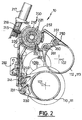
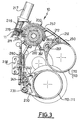
- the selector 210 is shown in extreme position, respectively in position of selection of the reverse gear for figure 2 and in fourth gear selection position for figure 3.
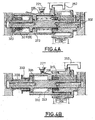
- FIGs 4, 4A, 4B there is shown in section the assembly of the selector 200. It is composed of the barrel 210, of the axis 300 and the carriage 220.
- the barrel 210 comprises at its periphery sector 212 cooperating with dog clutch 271 of fork control 230 surmounted by the toothed sector 214 of rotation control by the pinion 215 driven by the motor 217.
- the barrel is carried by the axis 300 on which it is fixed axially and in rotation by the pin 310, the carriage 220 carrying the finger 221 which cooperates with the control dog 252 fork 250.
- the axis 300 is guided by its ends in the casing 11.
- It has a shoulder 301 having a groove at its periphery containing a seal 311, and has two axial holes 302, 303, and two radial holes 304, 305 allowing the supply of pressurized fluid to both actuator chambers 306, 307.
- the pressurized fluid reaches the ends of the axis 300 by two supply conduits 12 and 13 opening into chambers 14 and 15.
- the tightness of the chambers 14 and 15 is provided by the seals 16 and 17 contained in two grooves machined in axis 15.
- the cart 220 is cylindrical, and has a partition 223 having in its center a cylindrical bore with a groove containing a seal 224. It is guided on the axis 300 by its partition 223 and by the shoulder 301. It is guided on the barrel 210 by the cylindrical surface 210.a which has a groove containing a seal 218.
- the axle assembly 300 and barrel 210 is held axially in the casing 11 in bearing on the latter on one side by the face 210b of the barrel and on the opposite side by a stop ring 326 associated with a shim washer 327.
- the central partition 223 of the carriage 220 acts as a piston. It forms with the surface cylindrical interior of the carriage, the cylindrical surface 210a of the barrel 210 and axis 300 a first compression chamber waterproof 306 supplied by conduits 302, 304 and allows the axial movement of the carriage to the left. It forms by elsewhere with the inner cylindrical surface of the carriage 220, the axis 300 and the shoulder 301 a second chamber of tight compression 307 supplied by conduits 303, 305, and allows axial movement of the carriage to the right.
- Mechanical return means position the carriage so that the fingers 221, 222 are centered relative to to the fork dogs 252, 262, 271, 281 themselves in neutral position.
- These means include a first cup 320 pressed against the shoulder 301 of the axis 300 by a first spring 321, which rests on a washer 322. This is stopped by the stop ring 323.
- They include a second cup 324 pressed against the barrel 210 by a second spring 325 also which pushes the carriage 220 against the first cup 320.
- the load of the first spring 321 being greater than that of the second spring 325, the carriage 220 is in an axial position of stable and precise support on the cup 320 in neutral position.
- FIG. 4A shows the carriage 220 in its three positions.
- FIG. 4A it is in its extreme position on the left corresponding to a first report position engaged.
- This position is obtained by supplying fluid under pressure the right chamber 306 through the conduits 302 and 304.
- the spring 321 pushes the cup 320 and the carriage 220 towards the right until the cup 320 comes into contact with the shoulder 301 of the shaft 300: this stable central position, illustrated in Figure 4 corresponds to neutral.
- the carriage 220 On the face 4B, the carriage 220 is pushed to the right in a second reporting position engaged.
- This position is reached in supplying pressurized fluid to the left chamber 307 by conduits 303 and 305. From this position, we return also in neutral position, establishing the same pressure in the two chambers 306, 307. The spring 325 then pushes the carriage 220 to the left, but only up to the cup 320, that is to say in the middle position of neutral since spring 321 is more loaded than spring 325.
- the middle partition 223 defines with the barrel selection 210 and axis 300 two compression chambers antagonists 306, 307.
- the partition 223 separates the two chambers so as to constitute a control piston in translation of the carriage 220 on axis 300 and on barrel 210.
- the return and the neutral position of the passage actuator 220 are provided by the counter springs 321 and 325, cooperating with the outer cup 320 plated in this position against a shoulder 301 of the axis 300, and against a end of the carriage 210 in neutral position.
- the first spring 321 pushing the carriage to the neutral position via the first cup 320 is more loaded than the second.
- the cart 220 can have on a angular sector a single or a double ramp 226, which cooperates with a contactor or potentiometer 227.
- the computer is thus informed of the axial position of the carriage, median, or gear position engaged on the left or on the right.
Landscapes
- Engineering & Computer Science (AREA)
- General Engineering & Computer Science (AREA)
- Mechanical Engineering (AREA)
- Gear-Shifting Mechanisms (AREA)
Abstract
Description
- plusieurs fourchettes de passage de vitesses coulissantes pouvant adopter une position neutre ou des positions de vitesses engagées, de part et d'autre de celle-ci,
- des moyens d'actionnement placés à l'extérieur de la boíte, comprenant d'une part un premier vérin à plusieurs positions stables pour sélectionner, par translation d'un doigt de passage selon son propre axe, la fourchette correspondant au passage de la vitesse souhaitée, et d'autre part un deuxième vérin à double effet, pour faire coulisser la fourchette et passer ainsi cette vitesse par rotation du doigt de passage.
- la figure 1 représente l'ensemble du dispositif de commande en position de sélection du rapport de première,
- la figure 2 représente l'ensemble du dispositif de commande en position extrême de sélection du rapport de marche arrière,
- la figure 3 représente l'ensemble du dispositif en position extrême de sélection du rapport de quatrième, et
- les figures 4, 4A, 4B représentent en coupe l'ensemble du sélecteur, le chariot étant respectivement en position de point mort et de rapports engagés,
Claims (21)
- Dispositif de commande de sélection et de passage des vitesses (10) d'une boíte de vitesses à arbres parallèles (100, 101, 102) et à pignons fous, comportant des moyens internes de sélection et de passage de vitesses déplaçant par l'intermédiaire de fourchettes d'actionnement (230, 240, 250, 260) des bagues de crabotage (110,111,112,113) des pignons fous, caractérisé en ce qu'il comporte un actionneur de sélection électromécanique (217) agencé à extérieur de la boíte et un actionneur hydraulique de passage (220) unique installé à l'intérieur de la boíte.
- Dispositif de commande selon la revendication 1 caractérisé en ce que les moyens de sélection et de passage des vitesses sont entraínés en rotation autour d'un axe parallèle aux arbres primaire (100) et secondaires (101, 102).
- Dispositif de commande selon la revendication 2, caractérisé en ce que les moyens comprennent un barillet de sélection cylindrique (210) entraíné en rotation par l'actionneur (217) et possède des secteurs périphériques (211, 212, 213) de plus grand diamètre qui assurent le désengagement des rapports et le verrouillage au point mort.
- Dispositif de commande selon la revendication 3, caractérisé en ce que l'actionneur hydraulique est constitué par un chariot de passage (220) cylindrique, concentrique au barillet (210) et placé à l'extérieur de ce dernier.
- Dispositif de commande selon la revendication 3 ou 4, caractérisé en ce que le barillet (210) comporte en périphérie un secteur denté (214) entraíné en rotation par l'actionneur (217).
- Dispositif de commande selon la revendication 3, 4 ou 5, caractérisé en ce que les moyens de sélection et de passage comportent un axe de support commun (300) du barillet (210) et du chariot (220) constituant avec ces derniers un sélecteur (200) disposé à l'intérieur de la boíte.
- Sélecteur de commande interne de boíte de vitesses caractérisé en ce qu'il comporte un barillet de sélection cylindrique (210) entraíné en rotation par un actionneur électromécanique (217) disposé à l'extérieur de la boíte, et un actionneur hydraulique de passage (220) unique.
- Sélecteur de commande selon la revendication 7, caractérisé en ce que le barillet (210) est entraíné en rotation par l'actionneur (217) et possèdent des secteurs périphériques (211, 212, 213) de plus grand diamètre qui assurent le désengagement des rapports et le verrouillage au point mort.
- Sélecteur de commande selon la revendication 7 ou 8, caractérisé en ce que l'actionneur hydraulique est constitué par un chariot de passage (220) cylindrique, concentrique au barillet (210) et placé à l'extérieur de ce dernier.
- sélecteur de commande selon la revendication 9, caractérisé en ce que le chariot (220) présente au moins un doigt (221, 222) mobile en translation axiale et entraíné en rotation par le barillet (210).
- Sélecteur de commande selon la revendication 10, caractérisé en ce que le déplacement en rotation des doigts (221, 222) assure la sélection des vitesses et en ce que leur déplacement en translation axiale assure l'engagement des vitesses.
- Sélecteur de commande selon l'une des revendications 7 à 11, caractérisé en ce que le barillet (210) comporte en périphérie un secteur denté (214) entraíné en rotation par l'actionneur (217).
- Sélecteur de commande selon l'une des revendications 9 à 12, caractérisé en ce que le chariot de passage (220) présente une partie cylindrique (220a), sur laquelle sont rapportés les doigts de passage (221,222).
- Sélecteur de commande selon la revendication 13, caractérisé en ce que la partie cylindrique (220a) du chariot est partiellement obstruée par une cloison médiane (223) définissant avec celle-ci, le barillet de sélection (210) et l'axe (300) deux chambres de compression antagonistes (306, 307).
- Sélecteur de commande selon la revendication 14, caractérisée en ce que la cloison (223) sépare les deux chambres de manière à constituer un piston de commande en translation du chariot (220) sur l'axe (300) et le barillet (210).
- Sélecteur de commande selon l'une des revendications 7 à 15, caractérisé en ce que le retour et le positionnement au point mort de l'actionneur de passage (220) sont assurés par un dispositif mécanique à ressorts antagonistes (321, 325).
- Sélecteur de commande selon la revendication 16, caractérisé en ce que le sélecteur (200) comporte une coupelle extérieure (320) plaquée contre un épaulement (301) de l'axe (300), et contre une extrémité du chariot (210) en position de point mort.
- Sélecteur de commande selon la revendication 17, caractérisé en ce que le sélecteur (200) comporte un premier ressort (321) repoussant le chariot vers la position de point mort par l'intermédiaire de la première coupelle (320) et un second ressort (325) moins chargé que le premier.
- Sélecteur de commande selon l'une des revendications des revendications 9 à 18, caractérisé en ce que le chariot (220) porte sur sa périphérie deux rampes en forme de V (226) coopérant avec un contacteur (227) ou un potentiomètre capable de renseigner en permanence un dispositif de contrôle sur la position axiale du chariot (220).
- Dispositif de commande de boíte de vitesses, caractérisé en ce qu'il comporte un sélecteur conforme à l'une des revendications 7 à 19.
- Boíte de vitesses caractérisée en ce qu'elle comporte un dispositif de commande ou un sélecteur conforme à l'une des revendications précédentes.
Applications Claiming Priority (2)
| Application Number | Priority Date | Filing Date | Title |
|---|---|---|---|
| FR0302142 | 2003-02-21 | ||
| FR0302142A FR2851631B1 (fr) | 2003-02-21 | 2003-02-21 | Dispositif et selecteur de commande de boite de vitesses |
Publications (2)
| Publication Number | Publication Date |
|---|---|
| EP1452784A1 true EP1452784A1 (fr) | 2004-09-01 |
| EP1452784B1 EP1452784B1 (fr) | 2007-09-26 |
Family
ID=32749710
Family Applications (1)
| Application Number | Title | Priority Date | Filing Date |
|---|---|---|---|
| EP04290376A Expired - Lifetime EP1452784B1 (fr) | 2003-02-21 | 2004-02-12 | Dispositif et selecteur de commande de boîte de vitesses |
Country Status (3)
| Country | Link |
|---|---|
| EP (1) | EP1452784B1 (fr) |
| DE (1) | DE602004009121T2 (fr) |
| FR (1) | FR2851631B1 (fr) |
Cited By (1)
| Publication number | Priority date | Publication date | Assignee | Title |
|---|---|---|---|---|
| CN101457831B (zh) * | 2007-12-13 | 2012-09-05 | 比亚迪股份有限公司 | 变速器的自动换档机构和自动换挡系统 |
Citations (4)
| Publication number | Priority date | Publication date | Assignee | Title |
|---|---|---|---|---|
| JPH07301331A (ja) * | 1994-04-28 | 1995-11-14 | Hino Motors Ltd | 機械式自動変速機の制御装置 |
| EP0928910A1 (fr) * | 1998-01-12 | 1999-07-14 | Aichi Kikai Kogyo Kabushiki Kaisha | Dispositif automatisé de changement de vitesse pour une boíte de transmission |
| EP1081416A2 (fr) * | 1999-09-01 | 2001-03-07 | AISIN AI Co., Ltd. | Dispositif de commande pour transmission |
| FR2814524A1 (fr) * | 2000-09-22 | 2002-03-29 | Magneti Marelli France | Actionneur pour boite de vitesses mecanique de vehicules |
Family Cites Families (2)
| Publication number | Priority date | Publication date | Assignee | Title |
|---|---|---|---|---|
| JPH0826934B2 (ja) * | 1987-09-29 | 1996-03-21 | 自動車機器株式会社 | 変速機の遠隔操作装置 |
| DE10146958A1 (de) * | 2001-09-24 | 2003-04-17 | Zahnradfabrik Friedrichshafen | Modul für Aktuatoren in einem Fahrzeug |
-
2003
- 2003-02-21 FR FR0302142A patent/FR2851631B1/fr not_active Expired - Fee Related
-
2004
- 2004-02-12 DE DE200460009121 patent/DE602004009121T2/de not_active Expired - Lifetime
- 2004-02-12 EP EP04290376A patent/EP1452784B1/fr not_active Expired - Lifetime
Patent Citations (4)
| Publication number | Priority date | Publication date | Assignee | Title |
|---|---|---|---|---|
| JPH07301331A (ja) * | 1994-04-28 | 1995-11-14 | Hino Motors Ltd | 機械式自動変速機の制御装置 |
| EP0928910A1 (fr) * | 1998-01-12 | 1999-07-14 | Aichi Kikai Kogyo Kabushiki Kaisha | Dispositif automatisé de changement de vitesse pour une boíte de transmission |
| EP1081416A2 (fr) * | 1999-09-01 | 2001-03-07 | AISIN AI Co., Ltd. | Dispositif de commande pour transmission |
| FR2814524A1 (fr) * | 2000-09-22 | 2002-03-29 | Magneti Marelli France | Actionneur pour boite de vitesses mecanique de vehicules |
Non-Patent Citations (2)
| Title |
|---|
| PATENT ABSTRACTS OF JAPAN vol. 013, no. 299 (M - 847) 11 July 1989 (1989-07-11) * |
| PATENT ABSTRACTS OF JAPAN vol. 1996, no. 03 29 March 1996 (1996-03-29) * |
Cited By (1)
| Publication number | Priority date | Publication date | Assignee | Title |
|---|---|---|---|---|
| CN101457831B (zh) * | 2007-12-13 | 2012-09-05 | 比亚迪股份有限公司 | 变速器的自动换档机构和自动换挡系统 |
Also Published As
| Publication number | Publication date |
|---|---|
| FR2851631A1 (fr) | 2004-08-27 |
| DE602004009121T2 (de) | 2008-06-26 |
| DE602004009121D1 (de) | 2007-11-08 |
| EP1452784B1 (fr) | 2007-09-26 |
| FR2851631B1 (fr) | 2006-03-03 |
Similar Documents
| Publication | Publication Date | Title |
|---|---|---|
| EP1585915B1 (fr) | Dispositif de commande interne de boite de vitesse mecanique | |
| EP1977140B1 (fr) | Groupe motopropulseur a moteur auxiliaire raccorde sur un arbre intermediaire de la boite de vitesses | |
| WO1999057463A1 (fr) | Boite de vitesses compacte | |
| FR2510492A1 (fr) | Appareil de changement de vitesses pour tracteur | |
| KR20090057091A (ko) | 차량용 변속기의 변속 제어 장치 | |
| EP1273825A2 (fr) | Boite de vitesses à arbres parallèles et procédé de commande des changements de rapport correspondants | |
| EP0490730B1 (fr) | Dispositif de commande motorisé de changement de rapports de transmission pour boîte de vitesses, en particulier pour véhicules automobiles | |
| US7632161B1 (en) | Marine transmission actuator | |
| EP1452784B1 (fr) | Dispositif et selecteur de commande de boîte de vitesses | |
| EP0433448A1 (fr) | Dispositif pour commander une transmission a organes multiples sur un vehicule | |
| FR2831632A1 (fr) | Boite de vitesses de vehicule automobile | |
| EP0737827B1 (fr) | Commande interne de boíte de vitesses avec dispositif de rappel d'organes de sélection | |
| EP1072823B1 (fr) | Tambour sélecteur de vitesses pour boíte de vitesses multiples de véhicules automobiles | |
| FR2976039A3 (fr) | Boite de vitesses a huit rapports a double embrayage | |
| FR2829215A1 (fr) | Actionneurs de vitesses | |
| EP0019534B1 (fr) | Dispositif de commande à fluide sous pression, notamment hydraulique, des changements de rapports d'une boîte de vitesses à rapports étagés | |
| FR2844570A1 (fr) | Dispositif de selection et de passage de vitesses pour une boite de vitesse pilotee de vehicule automobile | |
| FR3068755A1 (fr) | Actionneur de boite de vitesses comprenant un mecanisme d'actionnement divise de maniere axiale, pack systeme compose d'un actionneur electrique de boite de vitesses, d'un actionneur electrique de pompe et d'une plaque porte-soupape et systeme compose du pack systeme et d'une cloche de boite de vitesses. | |
| FR2912795A1 (fr) | Actionneur de transmission a ou moins trois configurations. | |
| EP1162380B1 (fr) | Ensemble synchroniseur pour une transmission de véhicule automobile | |
| US5476164A (en) | Solenoid actuated mechanical clutch | |
| EP1229274B1 (fr) | Boíte de vitesses mécanique à actionneurs de passage | |
| FR2896564A1 (fr) | Boite de vitesses robotisee a deux actionneurs. | |
| FR2700593A1 (fr) | Boîte à vitesse à engrènement permanent et périphérique d'arbres intermédiaires et moyeux accouplés par embrayages individuels hydrauliques commandés électriquement. | |
| FR2796697A1 (fr) | Dispositif de commande interne de changement de vitesse pour boite de vitesses mecanique d'un vehicule automobile |
Legal Events
| Date | Code | Title | Description |
|---|---|---|---|
| PUAI | Public reference made under article 153(3) epc to a published international application that has entered the european phase |
Free format text: ORIGINAL CODE: 0009012 |
|
| AK | Designated contracting states |
Kind code of ref document: A1 Designated state(s): AT BE BG CH CY CZ DE DK EE ES FI FR GB GR HU IE IT LI LU MC NL PT RO SE SI SK TR |
|
| AX | Request for extension of the european patent |
Extension state: AL LT LV MK |
|
| 17P | Request for examination filed |
Effective date: 20050301 |
|
| AKX | Designation fees paid |
Designated state(s): BE DE GB |
|
| GRAP | Despatch of communication of intention to grant a patent |
Free format text: ORIGINAL CODE: EPIDOSNIGR1 |
|
| GRAS | Grant fee paid |
Free format text: ORIGINAL CODE: EPIDOSNIGR3 |
|
| GRAA | (expected) grant |
Free format text: ORIGINAL CODE: 0009210 |
|
| AK | Designated contracting states |
Kind code of ref document: B1 Designated state(s): BE DE GB |
|
| REG | Reference to a national code |
Ref country code: GB Ref legal event code: FG4D Free format text: NOT ENGLISH |
|
| REF | Corresponds to: |
Ref document number: 602004009121 Country of ref document: DE Date of ref document: 20071108 Kind code of ref document: P |
|
| GBT | Gb: translation of ep patent filed (gb section 77(6)(a)/1977) |
Effective date: 20071108 |
|
| PLBE | No opposition filed within time limit |
Free format text: ORIGINAL CODE: 0009261 |
|
| STAA | Information on the status of an ep patent application or granted ep patent |
Free format text: STATUS: NO OPPOSITION FILED WITHIN TIME LIMIT |
|
| 26N | No opposition filed |
Effective date: 20080627 |
|
| PGFP | Annual fee paid to national office [announced via postgrant information from national office to epo] |
Ref country code: DE Payment date: 20120221 Year of fee payment: 9 |
|
| PGFP | Annual fee paid to national office [announced via postgrant information from national office to epo] |
Ref country code: GB Payment date: 20120221 Year of fee payment: 9 Ref country code: BE Payment date: 20120329 Year of fee payment: 9 |
|
| BERE | Be: lapsed |
Owner name: RENAULT S.A.S. Effective date: 20130228 |
|
| GBPC | Gb: european patent ceased through non-payment of renewal fee |
Effective date: 20130212 |
|
| REG | Reference to a national code |
Ref country code: DE Ref legal event code: R119 Ref document number: 602004009121 Country of ref document: DE Effective date: 20130903 |
|
| PG25 | Lapsed in a contracting state [announced via postgrant information from national office to epo] |
Ref country code: DE Free format text: LAPSE BECAUSE OF NON-PAYMENT OF DUE FEES Effective date: 20130903 Ref country code: GB Free format text: LAPSE BECAUSE OF NON-PAYMENT OF DUE FEES Effective date: 20130212 Ref country code: BE Free format text: LAPSE BECAUSE OF NON-PAYMENT OF DUE FEES Effective date: 20130228 |