EP1452837B1 - Ventil zum Regulieren und Messen des Durchflusses eines Fluids - Google Patents
Ventil zum Regulieren und Messen des Durchflusses eines Fluids Download PDFInfo
- Publication number
- EP1452837B1 EP1452837B1 EP04075561A EP04075561A EP1452837B1 EP 1452837 B1 EP1452837 B1 EP 1452837B1 EP 04075561 A EP04075561 A EP 04075561A EP 04075561 A EP04075561 A EP 04075561A EP 1452837 B1 EP1452837 B1 EP 1452837B1
- Authority
- EP
- European Patent Office
- Prior art keywords
- valve
- valve according
- fluid
- manifold
- branch pipe
- Prior art date
- Legal status (The legal status is an assumption and is not a legal conclusion. Google has not performed a legal analysis and makes no representation as to the accuracy of the status listed.)
- Expired - Lifetime
Links
- 239000012530 fluid Substances 0.000 title claims abstract description 38
- 230000001105 regulatory effect Effects 0.000 title claims abstract description 12
- 238000006073 displacement reaction Methods 0.000 claims description 6
- 244000273618 Sphenoclea zeylanica Species 0.000 claims description 4
- 230000013011 mating Effects 0.000 claims description 4
- 241000826860 Trapezium Species 0.000 claims description 3
- 238000006243 chemical reaction Methods 0.000 claims description 3
- 238000011144 upstream manufacturing Methods 0.000 claims description 2
- 230000033001 locomotion Effects 0.000 abstract description 3
- 238000005259 measurement Methods 0.000 description 16
- 230000033228 biological regulation Effects 0.000 description 7
- 238000007789 sealing Methods 0.000 description 3
- 230000001914 calming effect Effects 0.000 description 2
- 230000009977 dual effect Effects 0.000 description 2
- 238000010438 heat treatment Methods 0.000 description 2
- 230000015572 biosynthetic process Effects 0.000 description 1
- 238000004140 cleaning Methods 0.000 description 1
- 239000012535 impurity Substances 0.000 description 1
- 238000009434 installation Methods 0.000 description 1
- 230000002427 irreversible effect Effects 0.000 description 1
- 238000004519 manufacturing process Methods 0.000 description 1
- 238000000926 separation method Methods 0.000 description 1
- 230000001629 suppression Effects 0.000 description 1
- 239000012780 transparent material Substances 0.000 description 1
- 238000005406 washing Methods 0.000 description 1
- XLYOFNOQVPJJNP-UHFFFAOYSA-N water Substances O XLYOFNOQVPJJNP-UHFFFAOYSA-N 0.000 description 1
Images

Classifications
-
- F—MECHANICAL ENGINEERING; LIGHTING; HEATING; WEAPONS; BLASTING
- F16—ENGINEERING ELEMENTS AND UNITS; GENERAL MEASURES FOR PRODUCING AND MAINTAINING EFFECTIVE FUNCTIONING OF MACHINES OR INSTALLATIONS; THERMAL INSULATION IN GENERAL
- F16K—VALVES; TAPS; COCKS; ACTUATING-FLOATS; DEVICES FOR VENTING OR AERATING
- F16K3/00—Gate valves or sliding valves, i.e. cut-off apparatus with closing members having a sliding movement along the seat for opening and closing
- F16K3/22—Gate valves or sliding valves, i.e. cut-off apparatus with closing members having a sliding movement along the seat for opening and closing with sealing faces shaped as surfaces of solids of revolution
- F16K3/24—Gate valves or sliding valves, i.e. cut-off apparatus with closing members having a sliding movement along the seat for opening and closing with sealing faces shaped as surfaces of solids of revolution with cylindrical valve members
- F16K3/246—Combination of a sliding valve and a lift valve
-
- G—PHYSICS
- G01—MEASURING; TESTING
- G01F—MEASURING VOLUME, VOLUME FLOW, MASS FLOW OR LIQUID LEVEL; METERING BY VOLUME
- G01F1/00—Measuring the volume flow or mass flow of fluid or fluent solid material wherein the fluid passes through a meter in a continuous flow
- G01F1/05—Measuring the volume flow or mass flow of fluid or fluent solid material wherein the fluid passes through a meter in a continuous flow by using mechanical effects
- G01F1/20—Measuring the volume flow or mass flow of fluid or fluent solid material wherein the fluid passes through a meter in a continuous flow by using mechanical effects by detection of dynamic effects of the flow
- G01F1/22—Measuring the volume flow or mass flow of fluid or fluent solid material wherein the fluid passes through a meter in a continuous flow by using mechanical effects by detection of dynamic effects of the flow by variable-area meters, e.g. rotameters
- G01F1/26—Measuring the volume flow or mass flow of fluid or fluent solid material wherein the fluid passes through a meter in a continuous flow by using mechanical effects by detection of dynamic effects of the flow by variable-area meters, e.g. rotameters of the valve type
-
- G—PHYSICS
- G01—MEASURING; TESTING
- G01F—MEASURING VOLUME, VOLUME FLOW, MASS FLOW OR LIQUID LEVEL; METERING BY VOLUME
- G01F1/00—Measuring the volume flow or mass flow of fluid or fluent solid material wherein the fluid passes through a meter in a continuous flow
- G01F1/05—Measuring the volume flow or mass flow of fluid or fluent solid material wherein the fluid passes through a meter in a continuous flow by using mechanical effects
- G01F1/20—Measuring the volume flow or mass flow of fluid or fluent solid material wherein the fluid passes through a meter in a continuous flow by using mechanical effects by detection of dynamic effects of the flow
- G01F1/28—Measuring the volume flow or mass flow of fluid or fluent solid material wherein the fluid passes through a meter in a continuous flow by using mechanical effects by detection of dynamic effects of the flow by drag-force, e.g. vane type or impact flowmeter
-
- G—PHYSICS
- G01—MEASURING; TESTING
- G01F—MEASURING VOLUME, VOLUME FLOW, MASS FLOW OR LIQUID LEVEL; METERING BY VOLUME
- G01F15/00—Details of, or accessories for, apparatus of groups G01F1/00 - G01F13/00 insofar as such details or appliances are not adapted to particular types of such apparatus
- G01F15/005—Valves
Definitions
- the present invention relates to a valve for regulating and measuring the flow rate of a fluid through a manifold and a branch pipe inside the said manifold.
- each of the piping branches which depart from the manifold must be equipped with a valve for intercepting and regulating the flow so as to be able to compensate for the varying loss of head which occurs in the different panels owing to their specific dimensions and their distance from the distribution manifold.
- Valves which can be applied to said pipes are also known, said valves being able to perform regulation of the flow, effecting at the same time measurement of the latter, said measurement being displayed on a calibrated scale present on the valve body.
- valves are for example known from DE 35 09 718 which describes a valve which, although performing correctly its dual function (regulation/measurement), nevertheless has a drawback due to the fact that, during regulation, the element for detecting the pressure is movable axially together with the closing body displaying the graduated scale from which the measurement is read.
- the measurement duct in order to obtain a constant measurement upon variation in the flow rate (greater opening/closing of the obturator), the measurement duct must be necessarily designed with a cylindrical shape.
- the aforementioned systems are provided with a measuring/regulating element (flow meter) on the return branch and the fluid control valve with electrically and/or pneumatically and/or similarly operated actuator on the supply branch.
- a measuring/regulating element flow meter
- the main valve operates with the flow directed so as to close the valve and, under high pressure conditions, irreversible closing of the valve could also occur with consequent interruption in the heating.
- DE-U-9404156 suggests providing a constriction at the opening where the fluid enters into the valve branch pipe; this solution envisages a bell arranged above the valve seat and able to produce said constriction with the free edge of the said opening of the branch pipe.
- IT-MI2001A 2725 in the name of the present Applicant also discloses a valve in which the flow regulating element consists of a core piece which is movable axially with openings arranged on the side surface thereof.
- the technical problem which is posed, therefore, is that of providing a valve for intercepting and regulating the flow in fluid branch pipes, with an instrument for measuring and displaying the value of the said flow incorporated therein, which is suitable for installation on the branch supplying the user of the system and allows effective regulation and measurement of the flow rate, with indication of the measurement which is precise and linear as far as possible.
- valve should consist of a small number of parts and should be easy and inexpensive to manufacture and assemble.
- valve for regulating and measuring the flow rate of a fluid through a manifold and a branch pipe inside the said manifold, according to the characteristics of claim 1.
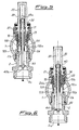
- a manifold 1 envisages at least one branch pipe 2 which has a substantially frustoconical shape, with the conicity directed from the manifold 1 towards the supply branch 1c of the system, and extends inside the manifold in a direction substantially transverse to that of the fluid flow; in the example shown in the Figure the branch pipe 2 is joined to the manifold 1 by means of a connection consisting of a screw 2a and female thread la with the arrangement of a sealing ring 3 in between.
- the free edge 2b corresponding to the smaller base of the branch pipe 2 forms the opening for entry of the fluid into the pipe, while the opposite opening 2c forms the outlet opening of the valve; the fluid flow therefore occurs from the manifold 1 to the branch pipe 2 towards the said supply branch 1c as indicated by the arrow.
- the flow rate of the valve may be regulated by means of the head 100 of an obturator 10 which is substantially cylindrical and provided with an external thread 10b suitable for mating with the female thread 20b of a union 20 forming the element for connecting the measuring instrument to the manifold 1, as will be further explained below.
- the said head 100 of the obturator 10 has a cylindrical shape which is internally hollow, with the cavity 111 directed towards the branch pipe 2.
- the external circumferential surface of the head 100 of the obturator 10 is provided with an annular edge 101 extending radially outwards and able to come into contact with a corresponding seat 2d of the valve formed coaxially with the opening 2b of the branch pipe (2) and along a diameter which is greater than the diameter of said inlet opening 2b.
- said seat 2d extends in the axial direction so that the plane corresponding to its free edge lies at a height axially greater than the height at which the plane corresponding to the free edge of inlet opening 2b into the pipe 2 lies; in other words, the seat 2d of the valve is upstream of the opening 2b for entry into the branch pipe 2 in the direction of flow of the fluid.
- This configuration results in the formation, between the head 110 of the obturator and the seat 2d of the valve, of a calming chamber 130 able to allow the fluid to assume a substantially laminar flow condition before its entry into the branch pipe 2, thereby drastically reducing the cavitation and turbulence affecting the fluid, with improvement in the measuring precision and noiseless operation of the valve during regulation of the flow rate.
- the same circumferential surface of said head 100 of the obturator 10 is provided with slits suitable for allowing entry of the fluid into the branch pipe in a radial direction as well as regulation of the flow rate depending on whether the valve is operated so as to open/close it.
- said slits have mutually varying shapes; more particularly:
- the obturator 10 has a coaxial through-duct 14 and an annular seat 13 extending over a suitable distance in the axial direction on the opposite side to that of the bell 111.
- the union 20 has in turn an external thread 20a suitable for mating with a corresponding female screw 1b of the manifold 1.
- the union 20 extends in the form of a cover 21 having, axially engaged therein, an internally hollow stem 30 which is axially inserted into said cover 21 with the arrangement, in between, of an O-ring sealing element 31 and axially restrained to the cover 21 by a reaction washer 32 inserted in a special seat of the cover.
- the end 33 of the stem 30 inside the manifold 1 has a shape suitable for mating axially with the corresponding seat 13 of the obturator 10 to which it is constrained with the arrangement of a sealing element 34 in between.
- connection between the hollow stem 30 and the seat 13 is achieved by means of radial projections 13a on the obturator 10 which engage in corresponding grooves 30a on the stem 30 so as to produce mutual constraining during rotation, but allow sliding of the obturator 10 in the axial direction.
- a movable rod 40 guided by a bush 41 integral with the walls of the said cavity 35 is engaged inside the axial cavity 35 of the stem 30.
- Said rod 40 extends axially through the said duct 14 of the obturator 10 into the branch pipe 2 and is movable axially with respect to the stem 30 from a top end-of-travel position in contact with the outer end of the stem 30 into a bottom end-of-travel position defined by a fixed annular locating element 41.
- the rod 40 forms essentially the actual measuring instrument of the valve and is, for this purpose, provided at its opposite ends, respectively at its end on the outside 40a and inside 40b of the manifold 1, with a first annular element 43 forming the measurement indicator and a second annular element 44 which forms the element for opposing the through-flow of the fluid and against which the latter exerts the pressure which produces measurement of the flow rate.
- Reading of the measurement is performed from a graduated scale 43a, which is printed on the external surface of the stem 30; in order to ensure visibility, from the outside, of the relative position of the indicator 43 with respect to the graduated scale 43a, the part of the stem outside the manifold is conveniently made of transparent material.
- the said indicator element 43 and the guide bush 41 have, arranged between them, a spring 46 which is coaxially arranged on the rod 40 and which prevents free falling of the said rod, ensuring at the same time calibration of the instrument.
- the displacement of the annular element 44 towards a larger cross-section of the pipe 2 following an increase in flow rate produces an increase in the cross-section of the flow in the measurement zone upon an increase in the said flow rate; as a result, it is possible to obtain, in combination with the trapezoidal shape of the slit 110a, a more linear measurement and therefore a more spaced distribution of the display scale on the external surface of the stem, enabling easier and more accurate reading by the user.
- the regulating and measurement valve according to the invention may be realized with the connecting pipe 2 overturned, namely with the larger base of the frustoconical shape being arranged inside the manifold 1: in this configuration the valve may be arranged on the return pipe of the system and operate with a fluid flow from the return pipe towards the said manifold 1.
Landscapes
- Physics & Mathematics (AREA)
- Fluid Mechanics (AREA)
- General Physics & Mathematics (AREA)
- Engineering & Computer Science (AREA)
- General Engineering & Computer Science (AREA)
- Mechanical Engineering (AREA)
- Flow Control (AREA)
- Lift Valve (AREA)
- Measuring Volume Flow (AREA)
Claims (19)
- Ventil zur Regulierung und Messung der Durchflussrate eines Fluids durch eine Rohrverzweigung (1) und ein Zweigrohr (2, 2b) mit einer Eintrittsöffnung (2b) in der genannten Rohrverzweigung (1) und einer Austrittsöffnung (2c), umfassend Mittel zur Unterbrechung des Durchflusses (10, 100) mit einem Absperrorgan (10) mit einem Kopf (100), der bei einer Bedienung eines zugeordneten Stellorgans (30) entlang einer axialen Richtung bewegbar ist, Mittel (44) zur Erfassung des durch den Durchfluss des Fluids ausgeübten Druckes, welche mit entlang der genannten axialen Richtung gegen eine entgegengesetzte Wirkung von elastischen Mitteln (46) bewegbaren Elementen (40) integral sind und einen Teil eines Instrumentes (43, 43a) zur Messung der Durchflussrate des Fluids bilden, eine Skala (43a), welche auf der äusseren Oberfläche eines Schaftes (30) des genannten Stellorgans angezeigt ist, wobei die genannten Mittel (10, 100) zur Unterbrechung des Durchflusses mit dem genannten Stellorgan (30) verbunden sind, das genannte Absperrorgan (10) ein Aussengewinde (10b) hat, welches zur Verbindung mit dem Innengewinde (20b) einer das Element zur Verbindung des Messinstruments (43, 43a) und der Rohrverzweigung (1) bildenden Verbindung (20) geeignet ist, und die Verbindung ihrerseits an der genannten Rohrverzweigung mittels einer Schrauben/Innengewinde-Verbindung fixiert ist, so dass eine Rotation des Schaftes (30) nur die Verschiebung der Mittel zur Unterbrechung des Durchflusses (10, 100) entlang der axialen Richtung ohne Verschiebung des Schaftes (30) entlang der axialen Richtung bewirkt, wobei die Mantelfläche des genannten Kopfes (100) mindestens einen Schlitz (110, 110, 120) für den Eintritt des Fluids in das Zweigrohr (2) in einer zur axialen Richtung quer verlaufenden Richtung hat, dadurch gekennzeichnet, dass die Mantelfläche des genannten Kopfes (100) eine ringförmige Kante (101) aufweist, welche sich in der quer verlaufenden Richtung nach aussen erstreckt und für die Berührung mit dem Sitz (2d) des Ventils geeignet ist, um ein Verschliessen des Letzteren herzustellen, dadurch, dass der genannte Sitz (2d) des Ventils koaxial mit der Eintrittsöffnung (2b) des Zweigrohrs (2) und entlang eines Durchmessers, welcher grösser als der Durchmesser der genannten Eintrittsöffnung (2b) des genannten Zweigrohrs ist, ausgebildet ist und dadurch, dass der genannte Sitz (2d) des Ventils sich in der axialen Richtung erstreckt, so dass die Ebene, welche mit seiner freien Kante übereinstimmt, auf einer Höhe liegt, welche stromaufwärts - in der axialen Richtung und in Strömungsrichtung des Fluids - gegenüber der Höhe liegt, bei welcher die Ebene liegt, welche mit der freien Kante der Eintrittsöffnung (2b) des Zweigrohrs (2) übereinstimmt.
- Ventil nach Anspruch 1, dadurch gekennzeichnet, dass der genannte mindestens eine Schlitz (110) in der Mantelfläche des Kopfes (100) des Absperrorgans (10) eine Form (110a) in der Form eines gleichschenkligen Trapezes hat.
- Ventil nach Anspruch 2, dadurch gekennzeichnet, dass der genannte mindestens eine Schlitz (110) eine Basis hat, welche auf der mit der Austrittsöffnung (2c) des Zweigrohrs (2) übereinstimmenden Seite angeordnet ist.
- Ventil nach Anspruch 3, dadurch gekennzeichnet, dass der genannte mindestens eine Schlitz (110) in seinem unterem mit der Basis übereinstimmenden Teil einen am Umfang erweiterten Teil (110b) hat.
- Ventil nach Anspruch 2, dadurch gekennzeichnet, dass der genannte Schlitz (110) eine Öffnung hat, welche so ausgebildet ist, dass der Durchfluss des gesamten, mit der maximal axial offenen Position übereinstimmenden Arbeitsflusses des Ventils ermöglicht wird.
- Ventil nach Anspruch 2, dadurch gekennzeichnet, dass es mindestens einen zusätzlichen Schlitz (120) hat.
- Ventil nach Anspruch 6, dadurch gekennzeichnet, dass der genannte zusätzliche Schlitz (120) eine rechteckige Form hat.
- Ventil nach Anspruch 6, dadurch gekennzeichnet, dass die Summe der Flächen der genannten Schlitze (10, 120) so ist, dass der Durchgang des Maximalflusses des Ventils herstellbar ist.
- Ventil nach Anspruch 1, dadurch gekennzeichnet, dass das genannte Zweigrohr (2) einen kegelstumpfartige Form hat.
- Ventil nach Anspruch 9, dadurch gekennzeichnet, dass die grössere Basis des kegelstumpfartigen Rohres bei der Austrittsöffnung (2c) angeordnet ist.
- Ventil nach Anspruch 9, dadurch gekennzeichnet, dass die grössere Basis des kegelstumpfartigen Rohres in der Rohrverzweigung (1) angeordnet ist.
- Ventil nach Anspruch 1, dadurch gekennzeichnet, dass die genannten Mittel zum Verschluss der Öffnung des Zweigrohrs aus dem genannten Absperrorgan (10) bestehen, welches an seinem freien Ende ein innen hohlen, zylindrischen Kopf (100) mit einem gegen das Zweigrohr (2) gerichteten Hohlraum (111) hat.
- Ventil nach Anspruch 12, dadurch gekennzeichnet, dass das genannte Absperrorgan (10) einen koaxialen Durchgangskanal (14) hat.
- Ventil nach Anspruch 1, dadurch gekennzeichnet, dass das genannte Absperrorgan (10) einen ringförmigen Sitz (13) hat, welcher sich auf der dem Hohlraum des Kopfs (110) gegenüberliegenden Seite über eine geeignete Länge in der axialen Richtung erstreckt.
- Ventil nach Anspruch 14, dadurch gekennzeichnet, das der genannte ringförmige Sitz (13) radiale Vorsprünge (13a) hat.
- Ventil nach Anspruch 15, dadurch gekennzeichnet, dass das Ende (33) des Schafes (30) im Innern der Rohrverzweigung (1) longitudinale Nuten (30a) hat, welche dazu geeignet sind, einen Eingriff mit übereinstimmenden ringförmigen Vorsprüngen (13a) des Sitzes (13) des Absperrorgans (10) zu ermöglichen.
- Ventil nach Anspruch 1, dadurch gekennzeichnet, dass die genannten Mittel zur Betätigung der Mittel zur Unterbrechung (10, 100) aus einem innen hohlen Schaft (30) bestehen, dessen freies Ende ausserhalb des Ventils die eine Teilung aufweisende Skala (43) des Messinstrumentes (43) aufweist.
- Ventil nach Anspruch 1, dadurch gekennzeichnet, dass das genannte Stellorgan (30) und Absperrorgan (10) mit der Rohrverzweigung (1) mittels der genannten Verbindung (20) verbunden sind, welche an der genannten Verbindung mittels einer aus der Schraube (20a) und dem Innengewinde (1 b) bestehenden Verbindung fixiert werden können.
- Ventil nach Anspruch 18, dadurch gekennzeichnet, dass die genannten Mittel (30) zur Betätigung des Absperrorgans (10) an der genannten Verbindung (20) mittels einer in einen Spezialsitz eines Deckels (21) der genannten Verbindung eingefügten Gegendruckscheibe (32) axial eingespannt sind.
Applications Claiming Priority (2)
| Application Number | Priority Date | Filing Date | Title |
|---|---|---|---|
| ITMI20030353 | 2003-02-27 | ||
| IT000353A ITMI20030353A1 (it) | 2003-02-27 | 2003-02-27 | Valvola di regolazione e misura della portata di un flusso di fluido. |
Publications (2)
| Publication Number | Publication Date |
|---|---|
| EP1452837A1 EP1452837A1 (de) | 2004-09-01 |
| EP1452837B1 true EP1452837B1 (de) | 2008-12-10 |
Family
ID=32750499
Family Applications (1)
| Application Number | Title | Priority Date | Filing Date |
|---|---|---|---|
| EP04075561A Expired - Lifetime EP1452837B1 (de) | 2003-02-27 | 2004-02-20 | Ventil zum Regulieren und Messen des Durchflusses eines Fluids |
Country Status (4)
| Country | Link |
|---|---|
| EP (1) | EP1452837B1 (de) |
| AT (1) | ATE417250T1 (de) |
| DE (1) | DE602004018212D1 (de) |
| IT (1) | ITMI20030353A1 (de) |
Families Citing this family (1)
| Publication number | Priority date | Publication date | Assignee | Title |
|---|---|---|---|---|
| DE102013002118B4 (de) * | 2013-02-08 | 2015-01-15 | Viega Gmbh & Co. Kg | Verteilerventil mit integrierter Durchflussmesseinheit |
Family Cites Families (8)
| Publication number | Priority date | Publication date | Assignee | Title |
|---|---|---|---|---|
| US2069309A (en) * | 1934-07-26 | 1937-02-02 | Roy O Henszey | Flow indicator |
| ATE209761T1 (de) * | 1997-06-11 | 2001-12-15 | Fs Engineering Fritz Spiess | Durchflussmesser |
| DE29806215U1 (de) * | 1998-04-04 | 1999-07-29 | Dumser Metallbau GmbH & Co. KG, 76829 Landau | Vorrichtung zum Anzeigen und Begrenzen der Durchflußmengen für einen Heizkreislauf |
| IT1316617B1 (it) * | 2000-01-31 | 2003-04-24 | Watts Cazzaniga S P A | Valvola di regolazione e misura della portata di un flusso di fluido |
| IT1319053B1 (it) * | 2000-10-23 | 2003-09-23 | Watts Cazzaniga S P A | Valvola di regolazione del flusso di mandata per radiatori a piastra e simili |
| DE20111656U1 (de) * | 2001-07-13 | 2002-11-21 | Reich KG, Regel- und Sicherheitstechnik, 35713 Eschenburg | Ventilvorrichtung und Verteilervorrichtung |
| ITMI20012725A1 (it) * | 2001-12-20 | 2003-06-20 | Watts Cazzaniga S P A | Valvola di regolazione e misura della partata di un flusso di fluido |
| CN1625674A (zh) * | 2002-04-22 | 2005-06-08 | 奥斯塔科公开股份有限公司 | 用于装在进口中的包括流量计的分配阀 |
-
2003
- 2003-02-27 IT IT000353A patent/ITMI20030353A1/it unknown
-
2004
- 2004-02-20 DE DE602004018212T patent/DE602004018212D1/de not_active Expired - Lifetime
- 2004-02-20 AT AT04075561T patent/ATE417250T1/de not_active IP Right Cessation
- 2004-02-20 EP EP04075561A patent/EP1452837B1/de not_active Expired - Lifetime
Also Published As
| Publication number | Publication date |
|---|---|
| EP1452837A1 (de) | 2004-09-01 |
| ITMI20030353A1 (it) | 2004-08-28 |
| DE602004018212D1 (de) | 2009-01-22 |
| ATE417250T1 (de) | 2008-12-15 |
Similar Documents
| Publication | Publication Date | Title |
|---|---|---|
| US10969263B2 (en) | Fluid meter | |
| CN101430025B (zh) | 流量检测阀 | |
| EP2923180B1 (de) | Ventilkugel zur direkten durchflussmessung | |
| EP1130364B1 (de) | Ventil zur Regelung und Messung der Strömungsgschwindigkeit eines Fluids | |
| US4389901A (en) | Fluid flow meter | |
| US7036789B2 (en) | Distribution valve comprising a flowmeter for installing in an inlet | |
| EP3172536B1 (de) | Durchflussmesser mit variabler öffnung mit lokaler federvorspannung | |
| US5698793A (en) | Flow meters | |
| EP0200563A2 (de) | Ventil für eine Prozessleitung | |
| US5381826A (en) | Fluid flow controller and meter | |
| US6119724A (en) | Two-way valve for regulating and measuring the flow rate of a fluid | |
| US7278320B1 (en) | Omni-directional pressure pickup probe | |
| US20140174197A1 (en) | Sensor module measuring and/or monitoring parameters of media flowing in pipelines and measuring system formed therewith | |
| RU2606541C1 (ru) | Распределительный клапан со встроенным блоком расходомера | |
| EP1452837A1 (de) | Ventil zum Regulieren und Messen des Durchflusses eines Fluids | |
| US4100799A (en) | Compound meter assembly | |
| US3695105A (en) | Hydraulic valve with fluid meter connections | |
| EP3128212B1 (de) | Instrument zur messung der strömungsgeschwindigkeit eines fluids | |
| EP1321746B1 (de) | Ventil zum Regulieren und Messen des Durchflusses eines Fluids | |
| US20060196551A1 (en) | Valve for regulating and measuring the flow rate of a fluid flow | |
| EP4575418A1 (de) | Kompakter hybrid-durchflussmesser zur messung des durchflusses in einem zweig eines rohrverteilers | |
| EP3203192B1 (de) | Durchflussmesser für thermohydraulische systeme | |
| US6786103B2 (en) | Water meters to be mounted in the pipe conduits of a nominal diameter class and method for operating such water meters |
Legal Events
| Date | Code | Title | Description |
|---|---|---|---|
| PUAI | Public reference made under article 153(3) epc to a published international application that has entered the european phase |
Free format text: ORIGINAL CODE: 0009012 |
|
| AK | Designated contracting states |
Kind code of ref document: A1 Designated state(s): AT BE BG CH CY CZ DE DK EE ES FI FR GB GR HU IE IT LI LU MC NL PT RO SE SI SK TR |
|
| AX | Request for extension of the european patent |
Extension state: AL LT LV MK |
|
| 17P | Request for examination filed |
Effective date: 20050210 |
|
| AKX | Designation fees paid |
Designated state(s): AT BE BG CH CY CZ DE DK EE ES FI FR GB GR HU IE IT LI LU MC NL PT RO SE SI SK TR |
|
| RAP1 | Party data changed (applicant data changed or rights of an application transferred) |
Owner name: WATTS CAZZANIGA S.P.A. Owner name: WATTS INDUSTRIES DEUTSCHLAND GMBH |
|
| RAP1 | Party data changed (applicant data changed or rights of an application transferred) |
Owner name: WATTS INDUSTRIES ITALIA S.R.L. Owner name: WATTS INDUSTRIES DEUTSCHLAND GMBH |
|
| 17Q | First examination report despatched |
Effective date: 20061117 |
|
| GRAP | Despatch of communication of intention to grant a patent |
Free format text: ORIGINAL CODE: EPIDOSNIGR1 |
|
| GRAS | Grant fee paid |
Free format text: ORIGINAL CODE: EPIDOSNIGR3 |
|
| GRAS | Grant fee paid |
Free format text: ORIGINAL CODE: EPIDOSNIGR3 |
|
| GRAA | (expected) grant |
Free format text: ORIGINAL CODE: 0009210 |
|
| AK | Designated contracting states |
Kind code of ref document: B1 Designated state(s): AT BE BG CH CY CZ DE DK EE ES FI FR GB GR HU IE IT LI LU MC NL PT RO SE SI SK TR |
|
| REG | Reference to a national code |
Ref country code: GB Ref legal event code: FG4D |
|
| REG | Reference to a national code |
Ref country code: CH Ref legal event code: EP |
|
| REG | Reference to a national code |
Ref country code: IE Ref legal event code: FG4D |
|
| REF | Corresponds to: |
Ref document number: 602004018212 Country of ref document: DE Date of ref document: 20090122 Kind code of ref document: P |
|
| REG | Reference to a national code |
Ref country code: CH Ref legal event code: NV Representative=s name: DR. LUSUARDI AG |
|
| PG25 | Lapsed in a contracting state [announced via postgrant information from national office to epo] |
Ref country code: FI Free format text: LAPSE BECAUSE OF FAILURE TO SUBMIT A TRANSLATION OF THE DESCRIPTION OR TO PAY THE FEE WITHIN THE PRESCRIBED TIME-LIMIT Effective date: 20081210 Ref country code: NL Free format text: LAPSE BECAUSE OF FAILURE TO SUBMIT A TRANSLATION OF THE DESCRIPTION OR TO PAY THE FEE WITHIN THE PRESCRIBED TIME-LIMIT Effective date: 20081210 Ref country code: SI Free format text: LAPSE BECAUSE OF FAILURE TO SUBMIT A TRANSLATION OF THE DESCRIPTION OR TO PAY THE FEE WITHIN THE PRESCRIBED TIME-LIMIT Effective date: 20081210 |
|
| NLV1 | Nl: lapsed or annulled due to failure to fulfill the requirements of art. 29p and 29m of the patents act | ||
| PG25 | Lapsed in a contracting state [announced via postgrant information from national office to epo] |
Ref country code: EE Free format text: LAPSE BECAUSE OF FAILURE TO SUBMIT A TRANSLATION OF THE DESCRIPTION OR TO PAY THE FEE WITHIN THE PRESCRIBED TIME-LIMIT Effective date: 20081210 Ref country code: RO Free format text: LAPSE BECAUSE OF FAILURE TO SUBMIT A TRANSLATION OF THE DESCRIPTION OR TO PAY THE FEE WITHIN THE PRESCRIBED TIME-LIMIT Effective date: 20081210 Ref country code: ES Free format text: LAPSE BECAUSE OF FAILURE TO SUBMIT A TRANSLATION OF THE DESCRIPTION OR TO PAY THE FEE WITHIN THE PRESCRIBED TIME-LIMIT Effective date: 20090321 Ref country code: BG Free format text: LAPSE BECAUSE OF FAILURE TO SUBMIT A TRANSLATION OF THE DESCRIPTION OR TO PAY THE FEE WITHIN THE PRESCRIBED TIME-LIMIT Effective date: 20090310 Ref country code: BE Free format text: LAPSE BECAUSE OF FAILURE TO SUBMIT A TRANSLATION OF THE DESCRIPTION OR TO PAY THE FEE WITHIN THE PRESCRIBED TIME-LIMIT Effective date: 20081210 |
|
| PG25 | Lapsed in a contracting state [announced via postgrant information from national office to epo] |
Ref country code: PT Free format text: LAPSE BECAUSE OF FAILURE TO SUBMIT A TRANSLATION OF THE DESCRIPTION OR TO PAY THE FEE WITHIN THE PRESCRIBED TIME-LIMIT Effective date: 20090511 Ref country code: CZ Free format text: LAPSE BECAUSE OF FAILURE TO SUBMIT A TRANSLATION OF THE DESCRIPTION OR TO PAY THE FEE WITHIN THE PRESCRIBED TIME-LIMIT Effective date: 20081210 Ref country code: SE Free format text: LAPSE BECAUSE OF FAILURE TO SUBMIT A TRANSLATION OF THE DESCRIPTION OR TO PAY THE FEE WITHIN THE PRESCRIBED TIME-LIMIT Effective date: 20090310 Ref country code: AT Free format text: LAPSE BECAUSE OF FAILURE TO SUBMIT A TRANSLATION OF THE DESCRIPTION OR TO PAY THE FEE WITHIN THE PRESCRIBED TIME-LIMIT Effective date: 20081210 |
|
| PG25 | Lapsed in a contracting state [announced via postgrant information from national office to epo] |
Ref country code: MC Free format text: LAPSE BECAUSE OF NON-PAYMENT OF DUE FEES Effective date: 20090228 Ref country code: SK Free format text: LAPSE BECAUSE OF FAILURE TO SUBMIT A TRANSLATION OF THE DESCRIPTION OR TO PAY THE FEE WITHIN THE PRESCRIBED TIME-LIMIT Effective date: 20081210 |
|
| PLBE | No opposition filed within time limit |
Free format text: ORIGINAL CODE: 0009261 |
|
| STAA | Information on the status of an ep patent application or granted ep patent |
Free format text: STATUS: NO OPPOSITION FILED WITHIN TIME LIMIT |
|
| PG25 | Lapsed in a contracting state [announced via postgrant information from national office to epo] |
Ref country code: DK Free format text: LAPSE BECAUSE OF FAILURE TO SUBMIT A TRANSLATION OF THE DESCRIPTION OR TO PAY THE FEE WITHIN THE PRESCRIBED TIME-LIMIT Effective date: 20081210 |
|
| 26N | No opposition filed |
Effective date: 20090911 |
|
| GBPC | Gb: european patent ceased through non-payment of renewal fee |
Effective date: 20090310 |
|
| REG | Reference to a national code |
Ref country code: IE Ref legal event code: MM4A |
|
| REG | Reference to a national code |
Ref country code: FR Ref legal event code: ST Effective date: 20091030 |
|
| PG25 | Lapsed in a contracting state [announced via postgrant information from national office to epo] |
Ref country code: IE Free format text: LAPSE BECAUSE OF NON-PAYMENT OF DUE FEES Effective date: 20090220 |
|
| PG25 | Lapsed in a contracting state [announced via postgrant information from national office to epo] |
Ref country code: FR Free format text: LAPSE BECAUSE OF NON-PAYMENT OF DUE FEES Effective date: 20090302 Ref country code: GB Free format text: LAPSE BECAUSE OF NON-PAYMENT OF DUE FEES Effective date: 20090310 |
|
| PG25 | Lapsed in a contracting state [announced via postgrant information from national office to epo] |
Ref country code: GR Free format text: LAPSE BECAUSE OF FAILURE TO SUBMIT A TRANSLATION OF THE DESCRIPTION OR TO PAY THE FEE WITHIN THE PRESCRIBED TIME-LIMIT Effective date: 20090311 |
|
| PG25 | Lapsed in a contracting state [announced via postgrant information from national office to epo] |
Ref country code: LU Free format text: LAPSE BECAUSE OF NON-PAYMENT OF DUE FEES Effective date: 20090220 |
|
| PG25 | Lapsed in a contracting state [announced via postgrant information from national office to epo] |
Ref country code: HU Free format text: LAPSE BECAUSE OF FAILURE TO SUBMIT A TRANSLATION OF THE DESCRIPTION OR TO PAY THE FEE WITHIN THE PRESCRIBED TIME-LIMIT Effective date: 20090611 |
|
| PG25 | Lapsed in a contracting state [announced via postgrant information from national office to epo] |
Ref country code: TR Free format text: LAPSE BECAUSE OF FAILURE TO SUBMIT A TRANSLATION OF THE DESCRIPTION OR TO PAY THE FEE WITHIN THE PRESCRIBED TIME-LIMIT Effective date: 20081210 |
|
| PG25 | Lapsed in a contracting state [announced via postgrant information from national office to epo] |
Ref country code: CY Free format text: LAPSE BECAUSE OF FAILURE TO SUBMIT A TRANSLATION OF THE DESCRIPTION OR TO PAY THE FEE WITHIN THE PRESCRIBED TIME-LIMIT Effective date: 20081210 |
|
| PGFP | Annual fee paid to national office [announced via postgrant information from national office to epo] |
Ref country code: IT Payment date: 20160223 Year of fee payment: 13 Ref country code: CH Payment date: 20160218 Year of fee payment: 13 |
|
| PGFP | Annual fee paid to national office [announced via postgrant information from national office to epo] |
Ref country code: DE Payment date: 20160324 Year of fee payment: 13 |
|
| REG | Reference to a national code |
Ref country code: DE Ref legal event code: R119 Ref document number: 602004018212 Country of ref document: DE |
|
| REG | Reference to a national code |
Ref country code: CH Ref legal event code: PL |
|
| PG25 | Lapsed in a contracting state [announced via postgrant information from national office to epo] |
Ref country code: CH Free format text: LAPSE BECAUSE OF NON-PAYMENT OF DUE FEES Effective date: 20170228 Ref country code: LI Free format text: LAPSE BECAUSE OF NON-PAYMENT OF DUE FEES Effective date: 20170228 |
|
| PG25 | Lapsed in a contracting state [announced via postgrant information from national office to epo] |
Ref country code: DE Free format text: LAPSE BECAUSE OF NON-PAYMENT OF DUE FEES Effective date: 20170901 |
|
| PG25 | Lapsed in a contracting state [announced via postgrant information from national office to epo] |
Ref country code: IT Free format text: LAPSE BECAUSE OF NON-PAYMENT OF DUE FEES Effective date: 20170220 |