EP1452908A1 - Linsenarray-blatt und übertragungsschirm und rückprojektionsanzeige - Google Patents
Linsenarray-blatt und übertragungsschirm und rückprojektionsanzeige Download PDFInfo
- Publication number
- EP1452908A1 EP1452908A1 EP02781873A EP02781873A EP1452908A1 EP 1452908 A1 EP1452908 A1 EP 1452908A1 EP 02781873 A EP02781873 A EP 02781873A EP 02781873 A EP02781873 A EP 02781873A EP 1452908 A1 EP1452908 A1 EP 1452908A1
- Authority
- EP
- European Patent Office
- Prior art keywords
- lens array
- lens
- layer
- disposed
- section
- Prior art date
- Legal status (The legal status is an assumption and is not a legal conclusion. Google has not performed a legal analysis and makes no representation as to the accuracy of the status listed.)
- Withdrawn
Links
Images






Classifications
-
- G—PHYSICS
- G03—PHOTOGRAPHY; CINEMATOGRAPHY; ANALOGOUS TECHNIQUES USING WAVES OTHER THAN OPTICAL WAVES; ELECTROGRAPHY; HOLOGRAPHY
- G03B—APPARATUS OR ARRANGEMENTS FOR TAKING PHOTOGRAPHS OR FOR PROJECTING OR VIEWING THEM; APPARATUS OR ARRANGEMENTS EMPLOYING ANALOGOUS TECHNIQUES USING WAVES OTHER THAN OPTICAL WAVES; ACCESSORIES THEREFOR
- G03B21/00—Projectors or projection-type viewers; Accessories therefor
- G03B21/54—Accessories
- G03B21/56—Projection screens
- G03B21/60—Projection screens characterised by the nature of the surface
- G03B21/62—Translucent screens
-
- G—PHYSICS
- G03—PHOTOGRAPHY; CINEMATOGRAPHY; ANALOGOUS TECHNIQUES USING WAVES OTHER THAN OPTICAL WAVES; ELECTROGRAPHY; HOLOGRAPHY
- G03B—APPARATUS OR ARRANGEMENTS FOR TAKING PHOTOGRAPHS OR FOR PROJECTING OR VIEWING THEM; APPARATUS OR ARRANGEMENTS EMPLOYING ANALOGOUS TECHNIQUES USING WAVES OTHER THAN OPTICAL WAVES; ACCESSORIES THEREFOR
- G03B21/00—Projectors or projection-type viewers; Accessories therefor
- G03B21/54—Accessories
- G03B21/56—Projection screens
- G03B21/60—Projection screens characterised by the nature of the surface
- G03B21/62—Translucent screens
- G03B21/625—Lenticular translucent screens
-
- G—PHYSICS
- G02—OPTICS
- G02B—OPTICAL ELEMENTS, SYSTEMS OR APPARATUS
- G02B3/00—Simple or compound lenses
- G02B3/0006—Arrays
- G02B3/0012—Arrays characterised by the manufacturing method
- G02B3/0031—Replication or moulding, e.g. hot embossing, UV-casting, injection moulding
-
- G—PHYSICS
- G02—OPTICS
- G02B—OPTICAL ELEMENTS, SYSTEMS OR APPARATUS
- G02B3/00—Simple or compound lenses
- G02B3/0006—Arrays
- G02B3/0037—Arrays characterized by the distribution or form of lenses
-
- G—PHYSICS
- G02—OPTICS
- G02B—OPTICAL ELEMENTS, SYSTEMS OR APPARATUS
- G02B3/00—Simple or compound lenses
- G02B3/0006—Arrays
- G02B3/0037—Arrays characterized by the distribution or form of lenses
- G02B3/0056—Arrays characterized by the distribution or form of lenses arranged along two different directions in a plane, e.g. honeycomb arrangement of lenses
Definitions
- the present invention relates to a projection display such as a projection television and display.
- the present invention relates to a lens array sheet which is suitable for such a usage and a projection screen which uses such a lens array sheet.
- CTR liquid crystal display device
- DMD Digital Micro-mirror Device
- a transparent (projection type, rear-projection type, rear type) projection television is representative.
- a screen is commonly known which is used for a projection television which is provided with a CRT projector having a structure shown in FIG. 10 for one of a conventional projection television screen.
- Such a screen is provided with a lentiular sheet 320 which has concave sections and convex sections for forming lens sections on it both surfaces and two pieces of lens sheet member for a fresnel lens sheet 310 such that the lenticular sheet 320 is disposed nearer to an observing person than the fresnel lens sheet 310.
- a plain protecting board (not shown in drawings) may be disposed on an outermost position near the observing person.
- the lenticular sheet 320 is formed by forming lens sections 322, 328 which are formed by disposing a plurality of cylindrical lens of which vertical direction is its longitudinal direction in a horizontal direction on both surfaces of the lenticular sheet 320.
- the lenticular sheet 320 has a lens section 328 for the observing person so as to adjust a color shift for an image light which is emitted from a three-tube projector which has colors such as R, G, and B by refracting and dispersing the image light and a lens section 322 near an emitting side compatibly. (Hereinafter, it may be called a double-surface lenticular sheet.)
- the double-surface lenticular sheet 320 should be formed by an extruding method in which optical axes of the lens sections on both surfaces must be aligned.
- a peripheral light other than the displayed image light should be reflected on the surface of the screen so as not disturb the observation and a shading layer 325 should be formed which is formed by a black stripe (BS) which corresponds to a non-light-condensing section in the cylindrical lens (that is, such as a non-transparent section for the image light) so as to have a smaller numerator in the above relationship.
- BS black stripe
- the double-surface lenticular sheet 320 is used for a projection television which is provided with a plurality of CRT projectors (in general, three sets such as R, G, and B).
- CRT projectors in general, three sets such as R, G, and B.
- a projection television which has only one set of projector (that is, a full-color display image is projected from a single lens) which is employs a method in which an LCD or a DMD is used for an optical engine section in the projector.
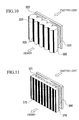
- FIG. 11 is a view for explaining an example for a structure for a transparent screen which is used for a single-tube projection television.
- the transparent screen formed by two members such as a lenticular sheet 370 and a fresnel lens sheet 360.
- a lens section 71 is formed on only a surface of the lenticular sheet 370. Also, a shading layer 375 is formed on a plain surface on which the lens section 371 is not formed.
- FIG. 5 is a detailed view for an example of a structure for a conventional transparent screen which is used for a liquid crystal projection television etc.
- reference numeral 1 indicates a fresnel lens.
- the fresnel lens 1 is formed by disposing a lens layer 1b which has convex sections and concave sections on a surface of a plate base member layer 1a concentrically.
- the projector is disposed near the base member layer 1a in the liquid crystal projection television.
- a lenticular sheet 2 is disposed near the lens layer 1b in the fresnel lens 1; thus, the transparent screen is formed by the fresnel lens 1 and the lenticular sheet 2.
- a structure of the lenticular sheet 2 is generally formed by a lenticular layer 3, a photo-sensitive resin layer 5, a shading layer 6, a bonding agent layer 7, and a dispersing layer 8 in which the lenticular layer 3 is disposed in the fresnel lens 1 and the dispersing layer 8 is disposed near the observing person.
- a hard coat layer 9 is disposed on a surface of the dispersing layer 8 which is near the observing person according necessity so as to protect the surface.
- the lenticular layer 3 is formed a plate base member layer 3a and a lens layer 3b which is disposed on its surface.
- the lens layer 3b is formed by disposing a plurality of half-cylindrical lenses 4 such that the longitudinal direction should be in parallel and a cylindrical surface 4a should be disposed near the fresnel lens 1.
- a lenticular layer 3b is formed by disposing a radiation curable resin under a non-hardened condition between a surface of the base member layer 3a and a mold (stamper) which has a reverse shape of the lens layer 3b, emitting a predetermined radiation from other surface of the base member layer 3a, and hardening the above resin. Also, the above lens layer 3b is bonded on the base member layer 3a; thus, a lenticular layer 3 is obtained.
- a photo-sensitive resin layer 5 is applied on a surface of the lenticular layer 3 near the base member layer 3a.
- a beam in a stripe manner is emitted so as to be condensed on the photo-sensitive resin layer 5 via the lenticular layer 3.
- the photo-sensitive resin layer 5 in a section which is exposed is denatured; thus the adhesiveness disappears.
- a transcription film which has a black transcription layer such as a black carbon is pressed on the photo-sensitive resin layer 5, the transcription layer is transcribed on an unexposed section which has an adhesiveness; thus, a shading layer 6 in a stripe manner in which a plurality of black lines are disposed is formed.
- a light is shaded by the shading layer 6 in a section through which the light does not transmit.
- plate dispersing layer 8 is further layered via a film adhesive layer 7 so as to be unified tightly; by doing this, a lenticular sheet 2 is obtained.
- the dispersing layer 8 is formed by mixing a dispersing member which is formed by a plurality of glass beads in a matrix which is made of a plastic member such as an acrylic member.
- a hard coat layer 9 is layered on a surface of the dispersing layer 8 according to necessity so as to be unified.
- the transparent screen is attached to a liquid crystal projector which is provided with a projector as shown in FIG. 5 and the light is emitted from the projector, the light becomes an approximate parallel light via the fresnel lens 1.
- a predetermined optical distribution angle is added by transmitting the light through the lenticular layer 3 such that the light disperses in a horizontal direction in the image appropriately; thus, the perspective angle is controlled in this direction.
- the light which transmits through the lenticular layer 3 becomes a stripe light which is parallel with a longitudinal direction of the cylindrical lens.
- a light disperses in a vertical direction appropriately by the function of the dispersing layer 8 via the shading layer 6; thus, the perspective angle is controlled in this direction.
- a lenticular layer and a dispersing layer are used in a combined manner so as to control the perspective angle of the image in a horizontal direction and a vertical direction in a conventional lenticular sheet and a transparent screen.
- problems such as a reduced gain (brightness) which is caused by a light absorption in the dispersing layer and a reduced S/N ration caused by the increase in a white dispersion.
- a method can be provided for controlling the perspective angle in the horizontal direction and the vertical direction by disposing the cylindrical lenses such that each longitudinal direction should be orthogonal to each other on both sides when two pieces of lenticular sheets are overlapped such that each longitudinal direction should be orthogonal to each other or a plurality of the cylindrical lenses are disposed on both surfaces of a base member layer.
- the cylindrical lens groups of which disposition direction are different from each other must be formed on both surfaces of one piece of the base material layer. Therefore, as similarly, it is necessary to perform the forming operations for the lens section twice.
- a lenticular lens sheet which forms a lens plate in which a plurality of lenticular lens elements (cylindrical lenses) which have lenticular lens shape on incident surface and fine lenticular lens shapes which are formed by a molding operation so as to be orthogonal with each other along surfaces of the cylindrical lenses.
- a dispersing layer which is formed by dispersing the optical dispersing particle and lenticular layer are used in a combined manner so as to control the perspective angle of the image in a horizontal direction and a vertical direction in a conventional lenticular sheet and a transparent screen.
- a diameter of a projection pupil in a projection lens is small in the transparent projection television which is provided with a liquid crystal projector. Therefore, as compared with a CRT transparent projection television, there have been inherent problems in that the brightness of the incident light from the projector is partially high (hot spot), the cylindrical lens may be observed to be bright in a stripe manner in a disposing direction (hot bar), and an unnecessary scintillation which is observed in a projection image may occur frequently.
- An object of the present invention is to provided a transparent screen in which there are fewer optical absorption and reduction in the gain (brightness) so as to restrict the white dispersion.
- Another object is to provide a transparent screen of which production cost is cheap.
- the invention of a first aspect of the present invention is a lens array sheet which is provided with a lens array layer which has a unified lens array wherein first lens arrays and second lens arrays which are formed by disposing a plurality of half-cylindrical lenses are disposed so as to cross each other orthogonally on a common plain.
- the invention of a second aspect of the present invention is a lens array sheet in which the first lens array is as high as the second lens array.
- the invention of a third aspect of the present invention is a lens array sheet in which the height of the first lens is different from the height of the second lens array.
- the invention of a fourth aspect of the present invention is a lens array sheet in which shading sections for shading a transmitting light are provided on a focal plain of the lens array layer.
- the invention of a fifth aspect of the present invention is a lens array sheet in which a cross section of the cylindrical lens is aspherical.
- the invention of a sixth aspect of the present invention is a lens array sheet in which the lens array layer is formed by a base material layer and a lens layer which is disposed on a surface of the lens array layer, and the lens layer is formed by a radiation curable resin.
- the invention of a seventh aspect of the present invention is a transparent screen which is provided with a lens array sheet according to any one of the first to fourth aspects.
- the invention of an eighth aspect of the present invention is a transparent screen according to the fifth aspect in which the fresnel lens is formed by a base material layer and a lens layer which is formed on a surface of the fresnel lens layer is formed by a radiation curable resin.
- the invention of a ninth aspect of the present invention is a rear-projection display device according to the seventh aspect or the eighth aspect further comprising the transparent screen.
- the invention of a tenth aspect of the present invention is a lens array sheet in which a first lens array which is formed by half-cylindrical lenses in parallel and half-cylindrical lenses which is formed by half-cylindrical lenses in parallel are disposed on a same plain such that longitudinal directions of the cylindrical lenses are orthogonal, the lens array is provided with a lens array layer which has a unified lens layer, and a plurality of cylindrical lenses are disposed so as to have intervals in parallel in either one of the first lens array or the second lens array.
- a valley section in the first valley section and a valley section in the second lens array may be disposed so as to coincide with each other.
- a shading layer is provided on a focal plane of the lens array so as to block the transmitting light.
- a thirteenth aspect of the present invention is a lens array sheet any one of the tenth aspect to twelfth aspect in which a plurality of cylindrical lenses are disposed in parallel without intervals in either one of the first lens array or the second lens array in which a plurality of cylindrical lenses are disposed in parallel with intervals.
- the cross section of the cylindrical lens in the first lens array may be aspherical in the lens array sheet.
- the lens array layer is disposed on a surface of the base material layer and the lens array layer is formed by a radiation curable resin.
- a rear-projection display device which is provided with the above aspect of the transparent screen is provided.
- a lens array sheet in which a first cylindrical lens which is formed by disposing a plurality of half-cylindrical lenses in parallel and a second lens array which is formed by disposing a plurality of half-cylindrical lenses in parallel are disposed on a same plain so as to be orthogonally approximately in longitudinal directions of the cylindrical lens in a lens array layer which has a unified lens layer, a peak of unit lens in the first lens array is continuous over the longitudinal direction, the second lens array is disposed by forming the unit lenses the peak of which is not continuous over a longitudinal direction between the peaks of the neighboring unit lenses in the first lens array.
- an eighteenth aspect of the present invention is a transparent screen which is provided with the above lens array sheet.
- the transparent screen of the present invention can be formed by the above lens sheet and the fresnel lens.
- a lens array sheet which is provided with a lens array layer which has a unified lens layer (hereinafter called an orthogonal lens section) is employed in which two lenticular sheets are not layered so as to be orthogonal in the longitudinal direction of the cylindrical lenses, nor the cylindrical lenses are disposed on both surfaces of the base member layer so as to be orthogonal in the longitudinal direction. Instead, the first lens array and the second lens array are disposed so as to be approximately orthogonal in the longitudinal direction of the cylindrical lenses on only one surface of a piece of the lens sheet.
- a first cylindrical lens which is formed by disposing a plurality of half-cylindrical lenses in parallel and a second lens array which is formed by disposing a plurality of half-cylindrical lenses in parallel are disposed on a same plain so as to be orthogonally approximately in longitudinal directions of the cylindrical lens in a lens array layer which has a unified lens layer, a peak of unit lens in the first lens array is continuous over the longitudinal direction, and the second lens array is disposed by forming the unit lenses the peak of which is not continuous over a longitudinal direction between the peaks of the neighboring unit lenses in the first lens array.
- At least the first lens array or the second lens array may be disposed in parallel via a plain section between the unit lenses. Also, it may be acceptable if the unit lenses are disposed without intervals therebetween.
- the optical distribution characteristics may be designed differently in the unit lens in the first lens array and the second lens array.
- the feature of the present invention which is designed for a suitable screen is that the first lens array is a lenticula (horizontal lenticular) which is formed by disposing cylindrical lens group in a horizontal direction so as to have a dispersing (distributing) characteristics in a horizontal direction, the second lens array is a lenticular (vertical lenticular) which is formed by disposing the cylindrical lens group in the vertical direction so as to have a vertical dispersing (distributing) characteristic.
- a relationship such as dispersion characteristics by the first lens array > dispersion characteristics by the second lens array is effective.
- a half angle aV (a measured angle in which a brightness of an emitted light which is measured orthogonally from a front surface to a lens array sheet is as a half as the half angle which is measured in an offset manner from the orthogonal condition) in the second lens array in a vertical direction is not fewer than 10 degree
- a perspective angle dV (a measured angle in which a brightness of an emitted light which is measured orthogonally from a front surface to a lens array sheet is as a twentieth half as the perspective angle which is measured in an offset manner from the orthogonal condition) in the second lens array in a vertical direction is not fewer than 35 degree.
- the lens layer of the lens array sheet and an opposite surface are plain surfaces, and a shading layer is formed on the plain surface to which a light is not condensed by the lens layer.
- the shading layer is formed by an aperture section which is continuous in a stripe manner according to the first lens array and an aperture section which is not continuous in an approximate spot manner according to the second lens array (each spot is in a stripe manner according to a light condensing section in the cylindrical lens).
- a ratio of the shading layer on the plain surface is suitable between 30 % and 90 %.
- a lens layer by a hardened product of radiation curable resin on a surface of a plain base member which is formed by radiation transmittable base material for a fine pitch lens array.
- the above lens array sheet is combined with a fresnel lens sheet which has a function for emitting the projection light from the projector in an approximate parallel light so as to form a transparent projection screen.
- the optical dispersing layer which is formed by dispersing the optical dispersing particle is formed in at least any section of the fresnel lens sheet and the lens array sheet for a common example for the transparent projection screen.
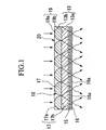
- FIG. 1 is a cross section which shows a lens array layer and a shading layer which form an example for a lens array sheet according to the present invention.
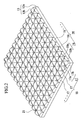
- FIG. 2 is an isometric view for showing the lens array layer.
- FIG. 3 is an isometric view showing a cross section which is viewed by cutting a part of the lens array layer shown in FIG. 2.
- the lens shapes for the lens array sheet shown in FIGS. 1 to 3 are designed.
- FIGS. 1 to 3 are drawn actually according to the designed shape.
- a main feature for this lens array sheet is a lens array layer 13.
- the lens array layer 13 is formed a plate base member layer 13a and a lens layer 13b which is disposed on its surface.
- the lens layer 13b is formed by a lens array 18 in which a plurality of half-cylindrical lenses 17 are disposed in parallel which are provided with a cylindrical surface 17 on a surface of a lens and a plain 17b on other surface such that the longitudinal directions, and a second lens array 20 which is formed by similarly disposing a plurality of cylindrical lenses 19 which are provided with a cylindrical surface 19a and a plain 19b such that the longitudinal directions are parallel.
- the cross section of the cylindrical lenses 17, 19 are not completely cylindrical (spherical lens). It is possible to use a commonly known non-half-circular shape (such as a second dimensional aspherical shape) such as a half-oval shape (oval surface lens), a parabolic shape (parabolic surface lens). Furthermore, it is possible to use a highly dimensional aspherical shape which has an item which is greater than a second dimension. It is possible to reduce an aberration for focusing an image when an aspherical lens is used; thus, it is possible to form an incident light in a fine pitch.
- a commonly known non-half-circular shape such as a second dimensional aspherical shape
- oval surface lens oval surface lens
- parabolic shape parabolic surface lens
- the plains 17b, 19b of the first lens array 18 and the second lens array 20 are disposed on a common plain (a surface of the base member layer 13a) such that the longitudinal direction of the cylindrical lens 17 which forms this and the longitudinal direction of the cylindrical lens 19 should be orthogonal so as to form a lens layer 13a.
- the cylindrical lens 17 and the cylindrical lens 19 are orthogonally cross crossing section 21 such that each of them engage with each other.
- the cylindrical lenses 17,17 ... and the cylindrical lenses 19, 19 ... are molded unitarily; thus, the lens array layer 13 is formed by a piece of member.
- a member to form the lens array layer 13 it is possible to use any member limitlessly as long as it can be used for an optical member because it is a transparent member such as a glass member or a plastic member. It is preferable to use a plastic member if a manufacturing efficiency is taken into account.
- a plastic member it is possible to name an acrylic resin such as poly(methyl methacrylate), a polycarbonate, an copolymer of acryl-stylene, a Stylene resin, and a Poly (vinyl chloride).
- a radiation curable resin such as an ultraviolet-ray curable resin or an electronic beam curable resin for a member for forming the lens layer 13b because it is possible to form a fine pitch.
- a radiation curable resin for example, it is possible to use a composition which is formed by doping a reaction diluting agent, a light polymerization starting agent, and an photosensitizer to a urethane(meta)acrylate and/or an epoxy(meta)acrylateoligomer.
- a urethane(meta)acrylateoligomer it is not limited in particular.
- polyols such as an ethyleneglycol, 1,4 butanediol, neopentylglycol, polycaprolactonepolyol, polyesterpolyol, polycarbonatediol, and poly(tetramethylene glycol)
- a polyisocyanate such as hexamethylene diisocyanate, isophorone diisocyanate, toluene diisocyanate, and xylene diisocyanate.
- an epoxy(meta)acrylateoligomer it is not limited in particular.
- a (meta)acrylic acid with an epoxy resin such as bisphenol A epoxy resin, bisphenol A epoxy resin, phenolnovolac type epocy resin, terminal glycidyl ether of an additional bishenol A propylene oxide, and a fluorene epoxy resin.
- an epoxy resin such as bisphenol A epoxy resin, bisphenol A epoxy resin, phenolnovolac type epocy resin, terminal glycidyl ether of an additional bishenol A propylene oxide, and a fluorene epoxy resin.
- the lens layer 13b is formed by applying a radiation curable resin under non-hardened condition on the base member layer 13a which is formed by a plastic member such a poly(ethylene terephthalate), polycarbonate, and vinyl chloride, compressing a molding stamper on a surface thereon, and emitting a predetermined radiation so as to harden.
- the molding stamper for example, by a following manner. That is, during manufacturing a molding stamper for molding a conventional lenticular, for example, a cutting section is formed on a surface of a cylindrical cylinder of which surface is made of a copper in a circular direction of the cylinder by using a cutting bype which has a corresponding shape to a unit lens which is supposed to be manufactured. Such cutting sections are formed in a plurality of sections in parallel, it is possible to obtain a stamper for lenticular. Furthermore, if the cutting sections are formed in a plurality of sections in parallel in an orthogonal direction to the cutting section in the circular direction, it is possible to obtain a molding stamper which is used for manufacturing the lens array layer 13 of the present invention.
- the lens array layer 13 it is possible to manufacture the lens array layer 13 according to a method which is similar to the method which is used for manufacturing a conventional lenticularl.
- a photo-sensitive resin layer 15 and further a shading layer 16 are disposed on other surface (focal plane) of the base member layer 13a.
- the photo-sensitive resin layer 15 and the shading layer 16 are manufactured in following manner. That is, as shown in FIG. 5, the photo-sensitive resin layer 15 in a section which is exposed through the lens array layer 13 is denatured by disposing the fresnel lens 1 in parallel under condition that the fresnel lens 1 should be used for a transparent screen actually and emitting a light from the lens layer 13b via the fresnel lens 1; thus, the adhesiveness disappears.
- a transcription film which has a black transcription layer such as a black carbon is pressed on the photo-sensitive resin layer 15, the transcription layer is transcribed on an unexposed section which has an adhesiveness; thus, a shading layer 16 is formed.
- the shading layer in the present invention is not limited to the above structure.
- following structure is preferable.
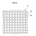
- a matrix focusing pattern is formed by a first focusing pattern in a stripe manner by condensing a light by the cylindrical lenses 17, 17 ... (first lens array 18) and a second focusing pattern in a stripe manner which is orthogonal to the first focusing pattern by condensing a light by cylindrical lenses 19,19 ... (second lens array 20). That is, the perspective angles of the light which is emitted from the lens layer 13b in both the vertical direction and the horizontal direction are controlled in a single operation by the first lens array 18 and the second lens array 20.
- FIG. 4 shows an example for such a focusing pattern.
- the shading layer 16 is formed so as to block a light which transmits through the lens array layer 13 via the fresnel lens 1 in a section in which the light should not transmit therethrough. Therefore, a plurality of approximate square shading sections 16a ... are disposed in both the vertical direction and the horizontal direction in a predetermined interval respectively according to such a focusing pattern.
- the dispersing layer 8 is not formed, it is preferable to form a lens array sheet by disposing a hard coat layer 9 on the shading layer 6.
- the lens layer 1b by applying a Radiation curable resin under a non-hardened condition on the base member layer 1a which is formed by a plastic member such as a poly(ethylene terephthalate), polycarbonate, poly (vinyl chloride) and compressing the molding stamper from thereon because it is possible to perform a fine molding operation so as to obtain fine-pitch product.
- a plastic member such as a poly(ethylene terephthalate), polycarbonate, poly (vinyl chloride)
- FIGS. 1 to 3 are designed.
- FIGS. 1 to 3 are drawn actually according to the designed shape.
- design parameters are determined as follows; thus, an experiment for proving the effect is performed.
- a test piece which has 30 mm x 30 mm size is produced according to such a design and an optical distribution characteristics is examined.
- approximately 30 degrees of perspective angle (half angle) is realized both in an up-down direction (vertical direction) and a left-right direction (horizontal direction).
- the perspective angle (half angle) indicates an angle which is a half of brightness in a front end of the lens array sheet.
- a focusing pattern in this lens array layer is similar to a focusing pattern which is shown in FIG. 4.
- a light is emitted from a projector to a lens array sheet on which a shading layer is disposed so as to correspond to such a focusing pattern, there is no problem in transmitting the light therethrough.
- the perspective angle is added in a conventional lenticular sheet only in a horizontal direction of the lens as explained above.
- FIGS. 6 and 7 show an example or the lens array sheet according to the present invention.
- FIG. 6 is an isometric view for the lens array sheet.
- FIG. 7 is a cross section.
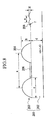
- FIG. 8 is a cross section for an important part of a prototype lens array sheet which is produced in an embodiment of the present invention which is explained later in an enlarged manner.
- This lens array sheet 201 is formed by a base member layer 202 which is formed by a transparent material member, and a lens array layer 203 which is disposed on a surface of the base material layer 202.
- a feature of the present invention resides in a structure of the lens array layer 203.
- a first lens array 205 which is formed by disposing a plurality of cylindrical lenses 204 without intervals therebetween in parallel and a second lens array 207 which is formed by disposing a plurality of cylindrical lenses 206 in a direction which is crossing, preferably orthogonal, to a longitudinal direction of the first lens array 205 are disposed on a common surface of the base member layer 202.
- a shading layer 211 is disposed on a surface which is opposite to the base member layer 2 on which the lens array layer 203 is formed which is a focal plane of the lens array.
- the shading layer 211 is formed by a plurality of shading aperture sections 210 for through which transmitting the emitted light 213 when an incident light 212 transmits the lens array layer 203 so as to be emitted from the focal plane and a shading material member such as a shading layer shading section 209 which is formed, for example, by a carbon black film which is disposed around the shading layer aperture sections 210.
- the cross sectional shape for the two cylindrical lenses 204, 206 which form the first lens array 205 and the second lens array 207 is not limited to spherical shape. It is possible to use a so called aspherical shape such as an oval surface, a parabolic surface (see cylindrical lens 4 shown in FIG. 3). It is possible to reduce an aberration for focusing an image when an aspherical lens is used; thus, it is possible to form an incident light in a fine pitch.
- a member to form the lens array layer 203 it is possible to use any member limitlessly as long as it can be used for an optical member because it is a transparent member such as a glass member or a plastic member. It is preferable to use a plastic member if a manufacturing efficiency is taken into account.
- an acrylic resin such as poly(methyl methacrylate), a polycarbonate, an copolymer of acryl-stylene, a Stylene resin, and a Poly (vinyl chloride).
- a radiation curable resin such as an ultraviolet-ray curable resin or an electronic beam curable resin for a member for forming the lens array layer 203b because it is possible to form a fine pitch.
- a radiation curable resin for example, it is possible to use a composition which is formed by doping a reaction diluting agent, a light polymerization starting agent, and an photosensitizer to a urethane(meta)acrylate and/or an epoxy(meta)acrylateoligomer.
- a urethane(meta)oligomer it is not limited in particular.
- polyols such as an ethyleneglycol, 1,4 butanediol, neopentylglycol, polycaprolactonepolyol, polyesterpolyol, polycarbonatediol, and poly(tetramethylene glycol)
- a polyisocyanate such as hexamethylene diisocyanate, isophorone diisocyanate, toluene diisocyanate, and xylene diisocyanate.
- an epoxy(meta)acrylateoligomer it is not limited in particular.
- a (meta)acrylic acid with an epoxy resin such as bisphenol A epoxy resin, bisphenol A epoxy resin, phenolnovolac type epocy resin, terminal glycidyl ether of an additional bishenol A propylene oxide, and a fluorene epoxy resin.
- an epoxy resin such as bisphenol A epoxy resin, bisphenol A epoxy resin, phenolnovolac type epocy resin, terminal glycidyl ether of an additional bishenol A propylene oxide, and a fluorene epoxy resin.
- the lens array layer 203 it is possible to manufacture the lens array layer 203, for example, by a following manner.
- a radiation curable resin is applied on the base member layer 202 which is formed by a plastic member under unhardened condition.
- a molding stamper is compressed on the surface so as to perform a mold pressing operation. Simultaneously, a predetermined radiation is emitted so as to harden it; thus, a lens array layer 203 is molded.
- the above explained molding stamper can form a lens layer, for example, in a following way. That is, during manufacturing a molding stamper for molding a conventional lenticular, for example, a cutting section is formed on a surface of a cylindrical cylinder of which surface is made of a copper in a circular direction of the cylinder by using a cutting byte which has a round edge shape. Such cutting sections are formed in a plurality of sections in parallel, it is possible to obtain a stamper for lenticular. Furthermore, a plurality of cutting sections are formed in a crossing direction, preferably in an orthogonal direction, to the cutting section in this circular direction, it is possible to obtain a molding stamper which can be used for manufacturing the lens array layer 3 which is a characteristic part of the present invention.
- the molding stamper for manufacturing the lens array layer 203 which is a characteristic part of the present invention by using a conventional technology easily; thus, the productivity is desirable.
- the lens array layer 1 according to a method which is similar to the method which is used for manufacturing a conventional lenticular lens sheet.
- a photo-sensitive resin layer which forms the lens array layer 203 and the shading layer 211 in a following way. If the fresnel lenses are disposed in parallel actually under a similar condition in which they are used for the transparent screen and a light is emitted from the lens layer of the lens array sheet via the fresnel lens, the photo-sensitive resin layer in a part which is exposed by alilght which transmits the lens array layer 203 is denatured; thus, an adhesiveness disappears. In addition, a transcription film which has a black transcription layer such as a black carbon is pressed on the photo-sensitive resin layer, the transcription layer is transcribed on an unexposed section which has an adhesiveness; thus, a shading layer 211 is formed.
- a focusing pattern in a ladder manner is formed by a stripe first focusing pattern which is formed by condensing a light by the cylindrical lens and a stripe second focusing pattern which is orthogonal to the first focusing pattern. That is, the perspective angles of the light which is emitted from the lens layer in both the vertical direction and the horizontal direction are controlled in a single operation by the first lens array and the second lens array.
- the shading layer 11 is disposed so as to block a light in a section through which the light does not transmit. Therefore, a plurality of shading sections are disposed according to such a focusing pattern regularly both in a vertical direction and a horizontal direction respectively.
- FIG. 9 is a view for another embodiment of a lens array sheet according to the present invention.
- the lens array sheet of the present invention is provided in which a first cylindrical lens which is formed by disposing a plurality of half-cylindrical lenses 204 in parallel and a second lens array which is formed by disposing a plurality of half-cylindrical lenses 207 in parallel are disposed on a same plain so as to be orthogonally approximately in longitudinal directions of the cylindrical lens in a lens array layer which has a unified lens layer, a peak of unit lens in the first lens array is continuous over the longitudinal direction, the second lens array is disposed by forming the unit lenses the peak of which is not continuous over a longitudinal direction between the peaks of the neighboring unit lenses in the first lens array. It is possible to realize an effect of the lens array sheet which is similar to the lens array sheet in the above explained first embodiment.
- design parameters a to g for the lens array sheets 201 which is shown in FIG. 8 are determined as follows and experiments are performed so as to prove the effects.
- the material member is a Polyethylene terephthalate. Its thickness d is 0.125 mm.
- the material member for the cylindrical lens 4 for the lens array layer 203 is a photo-sensitive resin layer.
- Interval a for the lenses is 0.252 mm.
- a protruding height b is 0.08 mm.
- Width c for the lens is 0.168 mm.
- a surface shape is an aspherical to which a high dimension is added with reference to an oval surface.
- the cylindrical lens 6 in the second lens array is formed such that an interval e between the lenses is 0.04079 mm, a protruding height is 0.008 mm, a curvature f is 0.03 mm so as to be a hemispherical shape.
- a Cromarin film which is a positive photo-sensitive resin adhesive layer of which adhesiveness disappears by being exposed to a light (a product of DUPON; trademark is registered) is used which has 20 ⁇ m thickness.
- a shading layer 211 which has an aperture which corresponds to a cylindrical lens which forms the lens array by performing a patterning operation for the photosensitive layer by emitting a parallel light which is collimated in 1° to 5° against a surface for forming a lens of the lens array sheet 201 and transcribing a black film (a transcription film of a carbon black) which has 2 ⁇ m thickness.
- FIG. 12 is a view for explaining an example for a structure of a transparent projection screen which relates to a lens array sheet according to an example of the present invention.
- a fresnel lens sheet 390 in which a lens section 392 is disposed on a surface of a base board 391 near a light emitting section and a lens array sheet 380 in which an orthogonal lens section 382 is disposed on a surface (near light emitting section) of a light dispersing base board 382 which is formed by dispersing an optical dispersing agent (particle) is disposed such that mutual lens sections 392, 382 should face each other.
- a transparent resin which is used for the base boards 392, 381 it is possible to use, for example, acrylic resin, polycarbonate resin, polyester resin, polyethylene resin, polyolefin resin, vynil chroride resin, polyimide resin, a blended product of the above resins, or a sheet or a film which is formed by copolymer.
- a member to form the lens sections 392, 382 it is possible to use any member limitlessly as long as it can be used for an optical member because it is a transparent member such as a glass member or a plastic member. It is preferable to use a plastic member if a manufacturing efficiency is taken into account.
- an acrylic resin such as polymethyl methacrylate, a polycarbonate, an copolymer of acryl-stylene, a Stylene resin, and a Polyvinyl chloride.
- a radiation curable resin such as an ultraviolet-ray curable resin or an electronic beam curable resin for a member for forming the lens sections 392, 382 because it is possible to form a fine pitch.
- a radiation curable resin for example, it is possible to use a composition which is formed by doping a reaction diluting agent, a light polymerization starting agent, and an photosensitizer to a urethane(meta)acrylate and/or an epoxy(meta)acrylateoligomer.
- urethane(meta)acrylateoligomer it is not limited in particular.
- polyols such as an ethyleneglycol, 1,4 butanediol, neopentylglycol, polycaprolactonepolyol, polyesterpolyol, polycarbonatediol, and poly(tetramethylene glycol)
- a polyisocyanate such as hexamethylene diisocyanate, isophorone diisocyanate, toluene diisocyanate, and xylene diisocyanate.
- an epoxy(meta)acrylateoligomer it is not limited in particular.
- an epoxy resin such as bisphenol A epoxy resin, bisphenol A epoxy resin, phenolnovolac type epocy resin, terminal glycidyl ether of an additional bishenol A propylene oxide, and a fluorene epoxy resin.
- a radiation curable resin is applied on the optical dispersing base board 381 which is formed mainly by the above transparent resin under unhardened condition.
- a molding stamper is compressed on the surface so as to perform a mold pressing operation. Simultaneously, a predetermined radiation is emitted so as to harden it; thus, a lens section 382 is molded.
- the lens array layer for example, by a following manner.
- a cutting section is formed on a surface of a cylindrical cylinder of which surface is made of a copper in a circular direction of the cylinder by using a cutting byte which has a round edge shape.
- Such cutting sections are formed in a plurality of sections in parallel, it is possible to obtain a stamper for lenticular.
- the cutting sections are formed in a plurality of sections in parallel in an orthogonal direction to the cutting section in the circular direction, it is possible to obtain a molding stamper which is used for manufacturing the lens array layer 313 of the present invention.
- the lens section 382 it is possible to manufacture the lens section 382 according to a method which is similar to the method which is used for manufacturing a conventional lenticular.
- Two lens array sheets were conventionally used by forming the lenticular sheets for a horizontal direction and a vertical direction so as to use the above explained orthogonal lens section 382.
- the first lens array and the second lens array which are formed by disposing a plurality of half columnar cylindrical lenses in parallel are disposed on a common surface such that the longitudinal directions of the cylindrical lenses should be approximately orthogonal.
- the lens array sheet is provided with a lens array layer which has a unified lens layer. Therefore, the perspective angles in the horizontal direction and the vertical direction are enlarged by a piece of the lens array sheet.
- a light distribution characteristics in the lens for the horizontal perspective angle (dispersing characteristics which is indicated by a half angle etc.) is designed to be large.
- the light distribution characteristics is controlled by factors such as a curvature of an arc in a cross section of the unit lens and a cutting depth into the unit lens.
- FIG. 13 An example for a structure in the orthogonal lens section 382 is shown in FIG. 13.
- FIG. 13A is a plan view for showing an example for an orthogonal lens section 382.
- a unit lens (horizontal perspective angle enlarging lens) 382H which forms a first lens array which enlarges the perspective angle in the horizontal direction has a cylindrical lens shape such that a peak section of the unit lens is continuous in a longitudinal direction.
- the unit lens (vertical perspective angle enlarging lens) 382V which forms a second lens array for enlarging the perspective angle in the vertical direction is formed such that the peak section of the unit lens is not continuous over the longitudinal direction (horizontal direction).
- the unit lenses 382H are disposed in parallel without intervals therebetween.
- the unit lenses 382V are disposed so as to be separated from each other.
- the present invention is not limited to such structures.
- FIG. 13B is a plan view for showing other example for an orthogonal lens section 382.
- FIG. 13B shows a structure in which the unit lenses are disposed in parallel so as to be separated from each other together with the first lens array and the second lens array.
- Both the unit lenses 382H, 382V are disposed so as to have a plane section between the unit lenses. As shown in the drawing, the unit lens 382V is disposed in a concave section (where the width of the unit lens is narrow) such that a border line which defines a valley section of the unit lens 82H is non-linear and continuous.
- the height of the unit lens 382H is higher than the height of the unit lens 382V (in the molding stamper which has a corresponding opposite shape, a valley section is disposed deeper).
- the peak section of the unit lens 382H is continuous linearly over the longitudinal direction of the cylindrical lens.
- the original shape for the cylindrical lens is less deformed in a structure shown in FIG. 13B in which a plain section is provided between the unit lenses and other unit lenses are disposed in a plain section. Therefore, it is possible to anticipate that the optical characteristics which correspond to the first lens array and the second lens array are maintained independently.
- the unit lenses 382H are disposed separately via the plain section.
- the unit lenses 382V are disposed without intervals.
- the unit lenses are disposed in parallel without intervals both in the first lens array and the second lens array.
- a shading layer is formed in a section which corresponds to a non-light condensing section according to the light condensing characteristics by the lens array on a plain surface near an opposite lens array in the lens array sheet shown in FIGS. 13A and 13B, such a condition indicates a structure shown in FIG. 14.
- a section which corresponds to a peak section of the lens array is a light condensing section so as to be a light transmitting section (aperture). Therefore, according to a fact that a peak section of the unit lens (horizontal perspective angle enlarging lens) which forms the first lens array is continuous in a longitudinal direction, in a stripe aperture (in the drawing, it is described for a horizontal direction transmitting section) and the unit lens (vertical perspective angle enlarging lens) 382V which forms the second lens array, according to a fact that the peak section of the unit lenses is formed in a non-continuous manner over a length direction (horizontal direction), an approximate spot aperture (it is described as a horizontal direction transmitting section in the drawing. Each spot is in a stripe manner which corresponds to a light condensing section in the cylindrical lens) is formed; thus, a shading pattern which is shown in the drawing is formed.
- a ratio which is occupied by the shading layer is preferably in a range of 30 to 90 % for observing a displayed image in a high contrast so as to be controlled by a light condensing characteristics of the lens array (a focusing condition in a plain surface which is opposite to the lens array) and a disposition of the unit lenses.
- a method such as a self-alignment method in which a position which corresponds to a non-light-condensing section in each lens section is determined accurately by using a light-condensing-characteristics of the lens section itself against a photosensitive resin layer which is formed on a surface which is opposite to the lens on the lens sheet for forming the shading layer.
- a position for condensing (focusing) a light by the lens section is set preferably inside the photosensitive resin layer according to the shading ratio for the pattern to be formed.
- a photosensitive adhesive agent which has a characteristics which becomes adhesive according to whether or not it is exposed to a light; thus, it is colored according to whether or not it is adhesive.
- Fig. 15 is a table for comparing optical characteristics in samples which are prototypes produced by various designs for a screen (examples 3-1 to 3-3) in which a lens array sheet of the present invention is used and a screen (comparative examples 1 and 2) in which a lenticular sheet is used in which conventional cylindrical lens groups are disposed in parallel in a direction (horizontal direction).
- a fresnel lens sheet (which does not have an optical dispersing layer which is formed by optical dispersing agent for a base member, and haze is 0 %) and a lenticular sheet (which is an H lens in which cylindrical lens groups are disposed in parallel in a horizontal direction such that an optical dispersing layer is provided on the base member, and haze is 80 %) are disposed from a projector to therefarther.
- a fresnel lens sheet which has an optical dispersing layer which is formed by optical dispersing agent for a base member, and haze is 60 %) and a lenticular sheet (which is an H lens in which the base member has an optical dispersing layer, and haze is 80 %) are disposed from a projector to therefarther.
- a fresnel lens sheet (which does not have an optical dispersing layer which is formed by optical dispersing agent for a base member, and haze is 0 %) and a lenticular sheet (which is an H lens in which cylindrical lens groups are disposed in parallel in horizontal/vertical directions such that an optical dispersing layer is provided on the base member, and haze is 80 %) are disposed from a projector to therefarther.
- V lens The structure for the cylindrical lens groups which are disposed in parallel in a vertical direction in the orthogonal lenses is called a V lens instead of the H lens.
- V and H the "lenticular lens (V)" and the “lenticular lens (H)” are itemized separately. These are formed unitarily so as to be described as cross lenticular lenses 1 and 2.
- the cross lenticular lens 1 is designed such that a value of angle aV should be 10 degrees.
- the cross lenticular lens 2 is designed such that a value of angle aV should be 20 degrees.
- a fresnel lens sheet which has an optical dispersing layer which is formed by optical dispersing agent for a base member, and haze is 60 %) and a lens array sheet (which is an orthogonal lens which has the same optical characteristics as that in the example 3-1 which has an optical dispersing layer on the base member, and haze is 80 %) are disposed from a projector to therefarther.
- a fresnel lens sheet which has an optical dispersing layer which is formed by optical dispersing agent for a base member, and haze is 60 %) and a lens array sheet (which is an orthogonal lens which does not have the same optical characteristics as those in the examples 3-1 and 3-2 which have an optical dispersing layer on the base member, and haze is 80 %) are disposed from a projector to therefarther.
- any of half angle áV (a measured angle in which a brightness of an emitted light which is measured orthogonally from a front surface to a lens array sheet is as a half as the half angle which is measured in an offset manner from the orthogonal condition) by the V lens in the vertical direction is 35° or greater.
- the optical distribution characteristics for not only the aV and dV but also ⁇ B and ⁇ V (measured angles in which a brightness of an emitted light which are measured orthogonally from a front surface to a lens array sheet are as 1/3, 1/10 respectively which is measured in an offset manner from the orthogonal condition) in the vertical direction are improved by the V lens function than in comparative examples (lower stages) which have more optical dispersing layers.
- FIG. 16 is a table for comparing an optical characteristics which relates to a contrast in the above examples 3-1 to 3-3 and the comparative examples 1 and 2.
- a difference for the contrast between the embodiments (300 to 330) and the comparative examples (220, 250) is outstanding in an observation condition which corresponds to a bright room under condition of 200 Lux or O Lux.
- the vertical perspective angle is broadened by the optical dispersing layer in the comparative example; therefore, it is necessary to user more amount of optical dispersing agent. Therefore, the contrast is reduced by broadening the perspective angle; thus, a phenomenon occurs in which a reappearance characteristics for the image are deteriorated.
- the first aspect of the present invention it is possible to control an optical distribution characteristics in both the vertical direction and the horizontal direction for the light which transmits through the lens array layer. Therefore, it is possible to restrict a material cost and a manufacturing cost with compared to a case in which two layers such as lens array layers are used, or the lens layers are formed on both surfaces of the base member layer. Also, it is possible to avoid the optical absorption by the dispersing layer and the reduction of the gain by omitting or simplifying the dispersing layer 8. As a result, it is possible to restrict a white dispersion phenomenon which is caused by the dispersing layer so as to realize a high S/N ratio.
- the shading layer it is possible to improve the S/N ratio by disposing the shading layer; thus, it is possible to provide an image which has a desirable contrast.
- the cross sectional shape of the cylindrical lens is aspherical; therefore, it is possible to reduce the aberration during a focusing operation and form the incident light in a fine pitch.
- the lens layer in the lens array layer is formed by the radiation curable resin; therefore, it is possible to perform a forming operation in a fine pitch.
- the fifth aspect of the present invention it is possible to provide a transparent screen which has the above effects by combining the lens array sheet and the fresnel lens which is described in any one of the first to fourth aspects.
- the lens layer in the fresnel lens is formed by the radiation curable resin; therefore, it is possible to perform a forming operation in a fine pitch.
- the present invention it is possible to control an optical distribution characteristics in both the vertical direction and the horizontal direction for the light which transmits through the lens array layer. Therefore, it is possible to restrict a material cost and a manufacturing cost with compared to a case in which two layers such as lens array layers are used, or the lens layers are formed on both surfaces of the base member layer.
- the shape for the cylindrical lenses in the unit lenses 382H and 382V are not deteriorated as shown in FIGS. 13A amd 13B. According to this fact, it is understood that it is possible to maintain each inherent optical characteristics independently even if the optical characteristics for the first lens and the second lens are designed separately so as to unify both of them; thus, it is possible to control the perspective angle characteristics (optical distribution characteristics) in the horizontal/vertical direction easily.
Landscapes
- Physics & Mathematics (AREA)
- General Physics & Mathematics (AREA)
- Optics & Photonics (AREA)
- Engineering & Computer Science (AREA)
- Manufacturing & Machinery (AREA)
- Overhead Projectors And Projection Screens (AREA)
Applications Claiming Priority (5)
| Application Number | Priority Date | Filing Date | Title |
|---|---|---|---|
| JP2001369216A JP4078832B2 (ja) | 2001-12-03 | 2001-12-03 | レンズアレイシートおよび透過型スクリーン |
| JP2001369216 | 2001-12-03 | ||
| JP2002241309A JP2004078049A (ja) | 2002-08-22 | 2002-08-22 | レンズアレイシートおよびそれを用いた透過型プロジェクションスクリーン |
| JP2002241309 | 2002-08-22 | ||
| PCT/JP2002/012655 WO2003048856A1 (en) | 2001-12-03 | 2002-12-03 | Lens array sheet and transmission screen and rear projection type display |
Publications (1)
| Publication Number | Publication Date |
|---|---|
| EP1452908A1 true EP1452908A1 (de) | 2004-09-01 |
Family
ID=26624852
Family Applications (1)
| Application Number | Title | Priority Date | Filing Date |
|---|---|---|---|
| EP02781873A Withdrawn EP1452908A1 (de) | 2001-12-03 | 2002-12-03 | Linsenarray-blatt und übertragungsschirm und rückprojektionsanzeige |
Country Status (7)
| Country | Link |
|---|---|
| US (2) | US7054068B2 (de) |
| EP (1) | EP1452908A1 (de) |
| KR (2) | KR100909715B1 (de) |
| CN (1) | CN100470364C (de) |
| CA (1) | CA2468869A1 (de) |
| TW (1) | TWI260429B (de) |
| WO (1) | WO2003048856A1 (de) |
Cited By (1)
| Publication number | Priority date | Publication date | Assignee | Title |
|---|---|---|---|---|
| EP2330568A1 (de) * | 2006-08-22 | 2011-06-08 | MEI, Inc. | Optische Detektoranordnung für Dokumentenakzeptor |
Families Citing this family (57)
| Publication number | Priority date | Publication date | Assignee | Title |
|---|---|---|---|---|
| US8035612B2 (en) * | 2002-05-28 | 2011-10-11 | Intellectual Ventures Holding 67 Llc | Self-contained interactive video display system |
| US8300042B2 (en) * | 2001-06-05 | 2012-10-30 | Microsoft Corporation | Interactive video display system using strobed light |
| US20050122308A1 (en) * | 2002-05-28 | 2005-06-09 | Matthew Bell | Self-contained interactive video display system |
| US7710391B2 (en) | 2002-05-28 | 2010-05-04 | Matthew Bell | Processing an image utilizing a spatially varying pattern |
| AU2003301043A1 (en) * | 2002-12-13 | 2004-07-09 | Reactrix Systems | Interactive directed light/sound system |
| CN1902930B (zh) * | 2003-10-24 | 2010-12-15 | 瑞克楚斯系统公司 | 管理交互式视频显示系统的方法和系统 |
| SG142126A1 (en) * | 2003-10-28 | 2008-05-28 | Sony Corp | A waveguide system, a device for displaying an image using such a system and a method for displaying an image |
| US8294992B2 (en) * | 2003-11-18 | 2012-10-23 | Merlin Technologies, Inc. | Projection-receiving surface |
| WO2005071474A2 (en) * | 2004-01-20 | 2005-08-04 | Sharp Kabushiki Kaisha | Directional backlight and multiple view display device |
| TWI253506B (en) * | 2004-07-14 | 2006-04-21 | Optimax Tech Corp | Method for manufacturing an optical sheet |
| KR100571367B1 (ko) * | 2004-08-27 | 2006-04-14 | 주식회사 코오롱 | 렌티큘러 렌즈 시트의 차광용 감광성 착색수지 조성물 및이를 이용한 차광 패턴형성방법 |
| JP2006106359A (ja) * | 2004-10-05 | 2006-04-20 | Seiko Epson Corp | レンズ基板の製造方法、レンズ基板、透過型スクリーンおよびリア型プロジェクタ |
| KR100662911B1 (ko) * | 2004-11-02 | 2007-01-02 | 삼성전자주식회사 | 렌티큘라 렌즈시트와 그 제조방법 |
| US9128519B1 (en) | 2005-04-15 | 2015-09-08 | Intellectual Ventures Holding 67 Llc | Method and system for state-based control of objects |
| US8081822B1 (en) | 2005-05-31 | 2011-12-20 | Intellectual Ventures Holding 67 Llc | System and method for sensing a feature of an object in an interactive video display |
| US8098277B1 (en) | 2005-12-02 | 2012-01-17 | Intellectual Ventures Holding 67 Llc | Systems and methods for communication between a reactive video system and a mobile communication device |
| US7502169B2 (en) * | 2005-12-07 | 2009-03-10 | Bright View Technologies, Inc. | Contrast enhancement films for direct-view displays and fabrication methods therefor |
| EP1855151B1 (de) * | 2006-05-10 | 2013-02-20 | Samsung Display Co., Ltd. | Optische Platte, Verfahren zur Herstellung einer optischen Platte, Hintergrundlichtanordnung und Flüssigkristallanzeigenvorrichtung |
| KR100837160B1 (ko) * | 2006-10-25 | 2008-06-11 | 엘지전자 주식회사 | 플라즈마 디스플레이 장치 |
| WO2008124820A1 (en) * | 2007-04-10 | 2008-10-16 | Reactrix Systems, Inc. | Display using a three dimensional vision system |
| KR100942490B1 (ko) * | 2007-09-05 | 2010-02-12 | 제일모직주식회사 | 전면에 광학부재를 구비하는 백라이트 유닛용 도광판 및이를 이용한 액정표시장치 |
| KR101141087B1 (ko) | 2007-09-14 | 2012-07-12 | 인텔렉츄얼 벤처스 홀딩 67 엘엘씨 | 제스처-기반 사용자 상호작용의 프로세싱 |
| US8159682B2 (en) * | 2007-11-12 | 2012-04-17 | Intellectual Ventures Holding 67 Llc | Lens system |
| US20090140048A1 (en) * | 2007-11-30 | 2009-06-04 | Symbol Technologies, Inc. | CPC Illumination Apparatus for an Imaging-Based Bar Code Reader |
| TWI416202B (zh) * | 2007-12-24 | 2013-11-21 | Kolon Inc | 光學元件 |
| US20100039500A1 (en) * | 2008-02-15 | 2010-02-18 | Matthew Bell | Self-Contained 3D Vision System Utilizing Stereo Camera and Patterned Illuminator |
| US8259163B2 (en) | 2008-03-07 | 2012-09-04 | Intellectual Ventures Holding 67 Llc | Display with built in 3D sensing |
| US8595218B2 (en) | 2008-06-12 | 2013-11-26 | Intellectual Ventures Holding 67 Llc | Interactive display management systems and methods |
| TWI418855B (zh) * | 2008-08-28 | 2013-12-11 | Ind Tech Res Inst | 多變曲率光學模組 |
| TWI378314B (en) * | 2008-10-15 | 2012-12-01 | Coretronic Corp | Screen of a projecting device |
| TWM378455U (en) * | 2009-12-07 | 2010-04-11 | Excellence Optoelectronics Inc | LED traffic signal device |
| US7948678B1 (en) | 2010-02-06 | 2011-05-24 | Merlin Technologies, Llc | Four-region catadioptric tile |
| US20120319999A1 (en) * | 2010-03-08 | 2012-12-20 | Dai Nippon Printing Co., Ltd. | Screens for use as displays of small-sized display devices with touch panel functions, and small-sized display devices with touch panel functions comprising said screens |
| USD633540S1 (en) * | 2010-03-19 | 2011-03-01 | Po-Sheng Lai | Polarization beam splitter |
| TWI452702B (zh) * | 2010-10-08 | 2014-09-11 | Univ Nat Sun Yat Sen | 可撓式集光罩及其製造方法 |
| JP2012094310A (ja) * | 2010-10-26 | 2012-05-17 | Panasonic Corp | 照明装置 |
| US8598772B2 (en) * | 2010-12-13 | 2013-12-03 | Samsung Corning Precision Materials Co., Ltd. | Flat display and method of fabricating the same |
| US20120170128A1 (en) * | 2010-12-31 | 2012-07-05 | Global Lighting Technologies Inc. | Optical panel |
| JP2012198396A (ja) * | 2011-03-22 | 2012-10-18 | Seiko Epson Corp | スクリーンの製造方法、及び部分スクリーン |
| KR101816580B1 (ko) * | 2011-04-29 | 2018-01-09 | 엘지전자 주식회사 | 영상 표시 시스템의 디스플레이 스크린 및 그 제조 방법 |
| US8587881B2 (en) * | 2011-07-05 | 2013-11-19 | Indian Institute Of Technology Kanpur | Miniature lenses, systems and methods of making the same |
| TW201310075A (zh) * | 2011-08-18 | 2013-03-01 | Hon Hai Prec Ind Co Ltd | 鏡片及具有該鏡片的相機模組 |
| EP2708935A1 (de) * | 2012-09-13 | 2014-03-19 | Fisba Optik Ag | Strahltransformationselement, Vorrichtung zur Transformation von elektromagnetischer Strahlung, Verfahren zur Herstellung eines Strahltransformationselements und Verfahren zur Transformation einer elektromagnetischen Emission |
| US20140077324A1 (en) * | 2012-09-20 | 2014-03-20 | Sony Corporation | Solid-state image pickup device, method of manufacturing solid-state image pickup device, and electronic apparatus |
| TWI551890B (zh) * | 2014-10-29 | 2016-10-01 | 台達電子工業股份有限公司 | 多視角立體顯示裝置及其角度放大屏幕 |
| JP6712372B2 (ja) | 2015-03-02 | 2020-06-24 | エーエスエムエル ネザーランズ ビー.ブイ. | 放射システム |
| DE102015214196B4 (de) * | 2015-07-27 | 2017-11-16 | Carl Zeiss Smt Gmbh | Vorrichtung zur Formung von Laserstrahlung sowie Beleuchtungssystem |
| KR101702095B1 (ko) | 2015-09-01 | 2017-02-03 | 주식회사 리치앤노블 | 구명용 에어밴드 |
| JP2017058585A (ja) * | 2015-09-18 | 2017-03-23 | 株式会社エンプラス | 画像表示体、その製造方法および光学部品 |
| EP3937246B1 (de) * | 2015-09-29 | 2025-11-19 | Dai Nippon Printing Co., Ltd. | Linsenfolie, linsenfolieneinheit, bildgebungsmodul, bildgebungsvorrichtung |
| JP7020405B2 (ja) * | 2016-05-25 | 2022-02-16 | 凸版印刷株式会社 | 光学素子版構造及び光学素子の製造方法 |
| CN111198093B (zh) * | 2018-11-16 | 2021-11-26 | 志圣工业股份有限公司 | 曝光光角量测设备 |
| CN110007552B (zh) * | 2018-12-14 | 2021-07-20 | 北京宝江科技有限公司 | 用于投影的透明薄膜和投影系统 |
| CN211857087U (zh) * | 2020-02-24 | 2020-11-03 | 宁波激智科技股份有限公司 | 一种减干涉准直膜 |
| CN114545533B (zh) | 2020-11-24 | 2024-08-06 | 京东方科技集团股份有限公司 | 微透镜结构、显示装置以及微透镜结构的加工方法 |
| CN115616832A (zh) * | 2021-07-16 | 2023-01-17 | 宏碁股份有限公司 | 照明模块及电子装置 |
| US12001099B2 (en) * | 2021-12-16 | 2024-06-04 | 3M Innovative Properties Company | Integral multilayer optical film |
Family Cites Families (17)
| Publication number | Priority date | Publication date | Assignee | Title |
|---|---|---|---|---|
| US2618198A (en) * | 1947-11-22 | 1952-11-18 | Eastman Kodak Co | Projection screen |
| JPS55135830A (en) | 1979-04-12 | 1980-10-23 | Matsushita Electric Ind Co Ltd | Transmission type screen |
| JPS5881526A (ja) | 1981-11-05 | 1983-05-16 | Canon Inc | 位置決め装置 |
| JPS5881526U (ja) * | 1981-11-27 | 1983-06-02 | 三菱レイヨン株式会社 | 透過型スクリ−ン |
| US4548469A (en) * | 1984-06-07 | 1985-10-22 | Mitsubishi Rayon Co., Ltd. | Rear projection screen |
| JPS61110127A (ja) | 1984-11-05 | 1986-05-28 | Mitsubishi Rayon Co Ltd | 透過型スクリ−ン |
| JP2722066B2 (ja) | 1987-09-02 | 1998-03-04 | 三井建設株式会社 | 鉄骨材の耐火被覆用治具と、耐火被覆用治具本体の突出寸法の設定方法 |
| US5122903A (en) | 1989-03-15 | 1992-06-16 | Omron Corporation | Optical device and optical pickup device using the same |
| US5361163A (en) * | 1991-06-03 | 1994-11-01 | Dai Nippon Printing Co., Ltd. | Reflection type projection screen, production process thereof, and production apparatus thereof |
| US5714218A (en) * | 1995-08-21 | 1998-02-03 | Dainippon Printing Co., Ltd. | Ionizing radiation-curable resin composition for optical article, optical article, and surface light source |
| JP3119164B2 (ja) | 1996-06-10 | 2000-12-18 | 日本電気株式会社 | アンテナへの着雪防止システム |
| JP3528520B2 (ja) | 1997-07-03 | 2004-05-17 | 株式会社日立製作所 | 背面投写形ディスプレイ装置及びそれに用いられるスクリーン |
| JPH11183706A (ja) | 1997-12-18 | 1999-07-09 | Toshiba Corp | 高集積光学素子及びその製造方法 |
| JPH11344769A (ja) * | 1998-06-01 | 1999-12-14 | Matsushita Electric Ind Co Ltd | 背面投写型スクリーン及び光拡散部材の製造方法 |
| JPH11344759A (ja) * | 1998-06-02 | 1999-12-14 | Asahi Optical Co Ltd | 表示動作制御装置 |
| JP3899681B2 (ja) | 1998-06-02 | 2007-03-28 | 凸版印刷株式会社 | レンチキュラーシートの露光装置 |
| KR19990046016A (ko) * | 1999-03-11 | 1999-06-25 | 김재진 | 멀티프로젝션스크린및그제조방법 |
-
2002
- 2002-12-03 CN CNB028241223A patent/CN100470364C/zh not_active Expired - Fee Related
- 2002-12-03 TW TW091135023A patent/TWI260429B/zh not_active IP Right Cessation
- 2002-12-03 CA CA002468869A patent/CA2468869A1/en not_active Abandoned
- 2002-12-03 EP EP02781873A patent/EP1452908A1/de not_active Withdrawn
- 2002-12-03 US US10/497,474 patent/US7054068B2/en not_active Expired - Fee Related
- 2002-12-03 KR KR1020047008343A patent/KR100909715B1/ko not_active Expired - Fee Related
- 2002-12-03 WO PCT/JP2002/012655 patent/WO2003048856A1/ja not_active Ceased
- 2002-12-03 KR KR1020097005666A patent/KR100936734B1/ko not_active Expired - Fee Related
-
2006
- 2006-02-27 US US11/362,006 patent/US7483214B2/en not_active Expired - Fee Related
Non-Patent Citations (1)
| Title |
|---|
| See references of WO03048856A1 * |
Cited By (3)
| Publication number | Priority date | Publication date | Assignee | Title |
|---|---|---|---|---|
| EP2330568A1 (de) * | 2006-08-22 | 2011-06-08 | MEI, Inc. | Optische Detektoranordnung für Dokumentenakzeptor |
| EP2717236A1 (de) * | 2006-08-22 | 2014-04-09 | MEI, Inc. | Optische Detektoranordnung für Dokumentenakzeptor |
| US8836926B2 (en) | 2006-08-22 | 2014-09-16 | Mei, Inc. | Optical detector arrangement for document acceptor |
Also Published As
| Publication number | Publication date |
|---|---|
| US20060176569A1 (en) | 2006-08-10 |
| US7483214B2 (en) | 2009-01-27 |
| US20050018306A1 (en) | 2005-01-27 |
| WO2003048856A1 (en) | 2003-06-12 |
| KR100936734B1 (ko) | 2010-01-14 |
| US7054068B2 (en) | 2006-05-30 |
| TWI260429B (en) | 2006-08-21 |
| CA2468869A1 (en) | 2003-06-12 |
| TW200304550A (en) | 2003-10-01 |
| CN100470364C (zh) | 2009-03-18 |
| KR20040071154A (ko) | 2004-08-11 |
| CN1599882A (zh) | 2005-03-23 |
| KR20090033500A (ko) | 2009-04-03 |
| KR100909715B1 (ko) | 2009-07-29 |
Similar Documents
| Publication | Publication Date | Title |
|---|---|---|
| US7054068B2 (en) | Lens array sheet and transmission screen and rear projection type display | |
| KR100918713B1 (ko) | 양면 렌즈 시트 및 프로젝션 스크린 | |
| US6970288B2 (en) | Micro-lens sheet and projection screen | |
| US7139124B2 (en) | Wide viewing angle screen and projection television comprising the same | |
| JP4178748B2 (ja) | レンズアレイシートおよび透過型スクリーン | |
| JP4251033B2 (ja) | レンズアレイシートおよび透過型スクリーン | |
| JP2003167298A (ja) | レンズアレイシートおよび透過型スクリーン | |
| TW200304579A (en) | Micro-lens sheet and projection screen | |
| JP2005017919A (ja) | 透過型スクリーン | |
| JP4882349B2 (ja) | レンズアレイシート、透過型スクリーンおよびリアプロジェクションテレビジョン | |
| JP4254403B2 (ja) | レンズアレイシートおよび透過型スクリーン | |
| JP2007256381A (ja) | 透過型スクリーン及び背面投射型ディスプレイ装置 | |
| JP2004078049A (ja) | レンズアレイシートおよびそれを用いた透過型プロジェクションスクリーン | |
| JP2003295324A (ja) | プロジェクションスクリーン | |
| JP2008076829A (ja) | 透過型スクリーンおよびその成型方法 | |
| KR20070035609A (ko) | 배면 투사형 스크린 및 배면 투사형 프로젝션 장치 | |
| JP2003107584A (ja) | 透過型スクリーン |
Legal Events
| Date | Code | Title | Description |
|---|---|---|---|
| PUAI | Public reference made under article 153(3) epc to a published international application that has entered the european phase |
Free format text: ORIGINAL CODE: 0009012 |
|
| 17P | Request for examination filed |
Effective date: 20040615 |
|
| AK | Designated contracting states |
Kind code of ref document: A1 Designated state(s): AT BE BG CH CY CZ DE DK EE ES FI FR GB GR IE IT LI LU MC NL PT SE SI SK TR |
|
| STAA | Information on the status of an ep patent application or granted ep patent |
Free format text: STATUS: THE APPLICATION HAS BEEN WITHDRAWN |
|
| 18W | Application withdrawn |
Effective date: 20070226 |