EP1453041B1 - Dispositif et procédé d' enregistrement de disque optique utilisant de strategie alternatifs pour réglage d' un faisceau laser - Google Patents
Dispositif et procédé d' enregistrement de disque optique utilisant de strategie alternatifs pour réglage d' un faisceau laser Download PDFInfo
- Publication number
- EP1453041B1 EP1453041B1 EP04004236A EP04004236A EP1453041B1 EP 1453041 B1 EP1453041 B1 EP 1453041B1 EP 04004236 A EP04004236 A EP 04004236A EP 04004236 A EP04004236 A EP 04004236A EP 1453041 B1 EP1453041 B1 EP 1453041B1
- Authority
- EP
- European Patent Office
- Prior art keywords
- strategy
- recording
- optical disk
- drive signal
- laser beam
- Prior art date
- Legal status (The legal status is an assumption and is not a legal conclusion. Google has not performed a legal analysis and makes no representation as to the accuracy of the status listed.)
- Expired - Lifetime
Links
- 230000003287 optical effect Effects 0.000 title claims abstract description 85
- 238000000034 method Methods 0.000 title claims abstract description 19
- 230000007423 decrease Effects 0.000 claims abstract description 15
- 230000003247 decreasing effect Effects 0.000 claims abstract description 15
- 230000004044 response Effects 0.000 claims description 5
- 230000001678 irradiating effect Effects 0.000 claims 2
- 238000010586 diagram Methods 0.000 description 6
- 230000015572 biosynthetic process Effects 0.000 description 5
- 230000007274 generation of a signal involved in cell-cell signaling Effects 0.000 description 5
- ANRHNWWPFJCPAZ-UHFFFAOYSA-M thionine Chemical compound [Cl-].C1=CC(N)=CC2=[S+]C3=CC(N)=CC=C3N=C21 ANRHNWWPFJCPAZ-UHFFFAOYSA-M 0.000 description 4
- IEQIEDJGQAUEQZ-UHFFFAOYSA-N phthalocyanine Chemical compound N1C(N=C2C3=CC=CC=C3C(N=C3C4=CC=CC=C4C(=N4)N3)=N2)=C(C=CC=C2)C2=C1N=C1C2=CC=CC=C2C4=N1 IEQIEDJGQAUEQZ-UHFFFAOYSA-N 0.000 description 3
- 230000000694 effects Effects 0.000 description 2
- 239000004065 semiconductor Substances 0.000 description 2
- 230000001419 dependent effect Effects 0.000 description 1
- 230000001737 promoting effect Effects 0.000 description 1
Images



Classifications
-
- G—PHYSICS
- G11—INFORMATION STORAGE
- G11B—INFORMATION STORAGE BASED ON RELATIVE MOVEMENT BETWEEN RECORD CARRIER AND TRANSDUCER
- G11B7/00—Recording or reproducing by optical means, e.g. recording using a thermal beam of optical radiation by modifying optical properties or the physical structure, reproducing using an optical beam at lower power by sensing optical properties; Record carriers therefor
- G11B7/12—Heads, e.g. forming of the optical beam spot or modulation of the optical beam
- G11B7/125—Optical beam sources therefor, e.g. laser control circuitry specially adapted for optical storage devices; Modulators, e.g. means for controlling the size or intensity of optical spots or optical traces
- G11B7/126—Circuits, methods or arrangements for laser control or stabilisation
- G11B7/1267—Power calibration
-
- G—PHYSICS
- G11—INFORMATION STORAGE
- G11B—INFORMATION STORAGE BASED ON RELATIVE MOVEMENT BETWEEN RECORD CARRIER AND TRANSDUCER
- G11B20/00—Signal processing not specific to the method of recording or reproducing; Circuits therefor
- G11B20/10—Digital recording or reproducing
- G11B20/12—Formatting, e.g. arrangement of data block or words on the record carriers
-
- G—PHYSICS
- G11—INFORMATION STORAGE
- G11B—INFORMATION STORAGE BASED ON RELATIVE MOVEMENT BETWEEN RECORD CARRIER AND TRANSDUCER
- G11B7/00—Recording or reproducing by optical means, e.g. recording using a thermal beam of optical radiation by modifying optical properties or the physical structure, reproducing using an optical beam at lower power by sensing optical properties; Record carriers therefor
- G11B7/004—Recording, reproducing or erasing methods; Read, write or erase circuits therefor
- G11B7/0045—Recording
- G11B7/00456—Recording strategies, e.g. pulse sequences
-
- G—PHYSICS
- G11—INFORMATION STORAGE
- G11B—INFORMATION STORAGE BASED ON RELATIVE MOVEMENT BETWEEN RECORD CARRIER AND TRANSDUCER
- G11B7/00—Recording or reproducing by optical means, e.g. recording using a thermal beam of optical radiation by modifying optical properties or the physical structure, reproducing using an optical beam at lower power by sensing optical properties; Record carriers therefor
- G11B2007/0003—Recording, reproducing or erasing systems characterised by the structure or type of the carrier
- G11B2007/0006—Recording, reproducing or erasing systems characterised by the structure or type of the carrier adapted for scanning different types of carrier, e.g. CD & DVD
Definitions
- the present invention relates to a recording method for recording information and a recording apparatus that records information on recordable optical disks such as CD-R (CD recordable) disks by applying a recording laser beam modulated by recording signals to an information recording surface, thereby alternately forming pits (marks) and lands according to mark length recording scheme.
- CD-R CD recordable
- the present invention enables recording with reduced crosstalk characteristics.
- the invention can improve the sound quality for music recording, for example.
- Recordable optical disk standards include CD-WO (CD Write Once).
- the CD-WO standard provides write-once recording in the CD format using CD-R disks.
- the pulse width of the recording signal is corrected by using a correction rule based on (n+K)T for pit length nT to be generated, where T is a time duration equivalent to a unit of pit length, n is a natural number ranging from 3 to 11 used as a multiplier to the pit length unit for generating the pit lengths, and K is a correction amount for the pulse width.
- This correction amount is constant independently of pit length n when optical disks of the same model are recorded at the same recording rate and at the same linear velocity.
- the laser is driven for recording by setting the laser power to an optimal value corresponding to the recording signal provided with the corrected pulse width.
- Such correction or setting rule is referred to as the recording strategy.
- the recording strategy provides correction or setting rules concerning pulse widths, rise and fall timings to start and stop irradiation, and recording powers for pulse waveforms of recording laser drive signals in order to generate optimal pit and land lengths.
- the recording strategy uses formula (n+K)T as a basic strategy concerning the timing axis of pulse waveforms such as pulse widths, and irradiation start and stop timings.
- n+K formula (n+K)T) as a basic strategy concerning the timing axis of pulse waveforms such as pulse widths, and irradiation start and stop timings.
- the recording strategy defines an asymmetry value of the reproduction signal.
- the asymmetry value is a parameter value concerning the reproduction waveform asymmetry and indicates how much the eye center of an eye pattern deviates from an amplitude center on the eye pattern for RF reproduction signals.
- the recording strategy is defined for each model and recording rate of CD-R disks and is stored in a memory of the CD-R disk recording and reproducing apparatus (CD-R drive).
- CD-R drive determines a disk model according to the lead-in start time and the like in the ATIP signal recorded as wobbles in the lead-in area.
- the drive reads the corresponding recording strategy from the memory in accordance with a combination of the determined disk model and the recording rate specified by a user.
- the drive uses the correction rule concerning the timing axis of the pulse waveform defined in the read recording strategy and performs a test record on the CD-R disk's test area by sequentially changing the recording power.
- the drive reproduces the recorded data from the test area to find an optimal recording power that can provide the asymmetry value defined in the recording strategy.
- This test recording completes the preparation before actual recording.
- the recording power is initialized to the determined optimal value in response to a user's operation.
- the actual recording is performed by correcting recording signals through the use of the correction rule defined in the read recording strategy concerning the timing axis of pulse waveforms.
- the following patent document 1 already discloses the technology concerning the recording strategy.
- the CD-R disks have been mainly used to record computer data. Recently, however, there is an increasing demand for recording music (audio data) on the CD-R disks. On the other hand, some audio amateurs criticize that the sound quality is degraded on a 80-minute CD-R disk (hereafter referred to as an 80-minute disk) having the data capacity of 700 MB as far as the conventional recording strategy is used.
- the present invention has been made in consideration of the foregoing. It is therefore an object of the present invention to provide an optical disk recording method and apparatus capable of recording audio data with reduced crosstalk characteristics, thereby improving the sound quality of music recording, for example.
- an optical disk recording method is provided as set forth in claim 1.
- an optical disk recording apparatus is provided as set forth in claim 12. Preferred embodiments of the present invention may be gathered from the dependent claims.
- the 80-minute disk having the data capacity of 700 MB is examined and proves rather degraded sound quality because its track pitch is 1.5 ⁇ m and that is narrower than 1.6 ⁇ m for that of a 74-minute recording CD-R disk (hereafter referred to as a 74-minute disk) having the data capacity of 650 MB.
- the narrow track pitch is considered to increase a crosstalk from an adjacent track during reproduction. That is to say, a large crosstalk from the adjacent track increases a servo load and degrades the sound quality due to power variations.
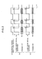
- FIG. 2(a) shows a recording signal before correction.
- FIGS. 2(b) and 2(c) show laser drive signals with the recording power specified so as to correct the pulse width of the recording signal using the recording strategy (n+K)T and to obtain a specified asymmetry value from the recording by using the corrected pulse width.
- FIG. 2(b) sets value K to a small value K1 (with the negative sign and a large absolute value) to shorten the pulse width.
- the recording power is set to a large value P1 so as to form a specified pit length by promoting the pit formation due to the residual heat.
- FIG. 2(c) sets value K to a high value K2 (with the negative sign and a small absolute value) to lengthen the pulse width.
- the recording power is set to a small value P2 so as to form a specified pit length by suppressing the pit formation due to the residual heat.
- the signals (b) and (c) are recorded so as to produce the same pit signal length. Since the signal (b) uses a higher recording power, the residual heat promotes the bit formation widthwise. Pit width W1 for the signal (b) is larger than pit width W2 for the signal (c).
- the recording using the signal (b) decreases a pit interval between adjacent tracks.
- a reproducing beam spot is easily applied to the adjacent pit to cause an increased crosstalk.
- the high recording power enables excellent pit formation and decreases a jitter.
- the recording using the signal (c) increases a pit interval between adjacent tracks because the pit width W2 is small.
- a reproducing beam spot is hardly applied to the adjacent pit to cause a decreased crosstalk.
- the low recording power results in degraded pit formation and increases a jitter.
- FIGS. 3 through 6 show characteristics of reproduction signals after 4x recording on a cyanine CD-R disk manufactured by a certain company by setting the correction value K1 for FIG. 2(b) to -0.5 and the correction value K2 for FIG. 2(c) to -0.2.
- the asymmetry value varies with the recording power.
- FIG. 3 shows changes of pit jitters in accordance with changes of asymmetry values.
- FIG. 4 shows changes of land jitters in accordance with changes of asymmetry values.
- FIG. 5 shows changes of C1 errors in accordance with changes of asymmetry values.
- FIG. 6 shows changes of crosstalk values in accordance with changes of asymmetry values. According to FIGS. 3 and 4 , it is understood that recording using the short pulse in FIG.
- FIG. 2(b) causes smaller jitters on the whole than recording using the long pulse in FIG. 9(c) .
- FIG. 5 it is understood that recording using the short pulse in FIG. 2(b) causes a fewer error occurrences in a wide range of asymmetry values than recording using the long pulse in FIG. 9(c) . Consequently, rather than recording using the long pulse in FIG. 2(c) , recording using the short pulse in FIG. 2(b) provides a wide power margin, i.e., a laser power range that keeps jitters and C1 errors below the respective specified criteria.
- FIG. 6 it is understood that recording using the long pulse in FIG.
- a plurality of recording strategies having different values K for recording on optical disks with the same model number at the same recording rate and the same linear velocity.
- the pulse width is increased and the recording power is decreased to prevent the pit width from increasing and to decrease crosstalk.
- Increasing the pulse width slightly increases jitters and possibilities of read error occurrences during reproduction.
- the occasional occurrence of random errors does not cause too large a noise.
- recording computer data uses a shorter pulse width and a higher recording power to form sharp pits. This decreases jitters during reproduction and minimizes read error occurrences. Increasing the recording power slightly increases crosstalks. However, this causes no problem because computer data is independent of the sound quality. Since just a single error may cause a fatal error, the effect of minimizing read error occurrences is significant.
- the present invention attaches importance to crosstalks for music recording and to jitters for computer data recording.
- the present invention provides a plurality of types of recording strategies and allows them to be selectively used for recording on optical disk with the same model number at the same recording rate and the same linear velocity.
- FIG. 7 shows a system configuration of an optical disk recording and reproducing apparatus (CD-R disk recording and reproducing apparatus) according to the present invention.
- An optical disk recording apparatus 1 can be configured to be a standalone CD-R recording and reproducing apparatus, a combination of a CD-R drive and a personal computer, and the like.
- An input device 28 is used by a user to enter a recording rate.
- the input device 28 is also used by a user to change recording modes.
- the recording mode changeover operation signifies an instruction to change between normal recording in preference to decrease of jitters and recording in preference to decrease of crosstalks.
- the recording mode changeover operation signifies an instruction to change between normal recording of computer data and recording of music data.
- a disk servo circuit 16 controls revolutions of a spindle motor 12 at a constant linear velocity according to a specified recording rate.
- the linear velocity is set to a value from 1.2 through 1.4 m/s for 1x speed recording, to a value twice as large as 1x speed recording, to a value quadruple as large as 1x speed recording, and so on according to the recording rate.
- the CD-WO standard specifies the constant linear velocity control so that a pre-groove wobble becomes 22.05 kHz.
- the wobble can be detected from an output signal of an optical head 13, i.e., from the remainder of a tracking error signal.
- the spindle motor 12 is PLL-controlled so that the wobble can be detected at the specified frequency such as 22.05 kHz for 1x speed, 44.1 kHz for 2x speed, 88.2 kHz for 4x speed, and so on.
- a focus and tracking servo circuit 18 controls a focus and tracking of a laser beam 11 irradiated from a semiconductor laser in the optical head 13.
- the tracking control is performed by detecting the pre-groove formed on an optical disk 10.
- a feed servo circuit 17 drives a feed motor 20 to move the optical head 13 along the radial direction of the optical disk 10.
- Digital or analog input signals are recorded on an optical disk (CD-R disk) 10 at a speed corresponding to the recording rate.
- a digital signal is directly input to a recording signal generation circuit 22.
- An analog signal is input to the recording signal generation circuit 22 via an A/D converter 24.
- the recording signal generation circuit 22 interleaves input data and supplies an error check code.
- the recording signal generation circuit 22 also supplies TOC, TOC information generated from a subcode generation circuit 23, and subcode information.
- the recording signal generation circuit 22 then performs EFM modulation, generates serial data in a CD standard format at a transfer rate corresponding to the recording rate, and outputs this data as a recording signal.
- This recording signal is input to a recording signal correction section (recording signal correction circuit) 26 via a drive interface 15.
- the recording signal correction section 26 uses the preset recording strategy concerning timing axes (pulse widths and start/stop timings) of recording signal pulses to correct the timing axis of the recording signal.
- the recording strategy is predefined in accordance with a combination of the model number (indicating which disk manufacturer made the CD-R disk) of the optical disk 10 to be used, the recording rate, and the recording mode.
- the recording signal is then input to a laser generator section (laser generation circuit) 25.
- the laser generator section 25 drives the semiconductor laser in the optical head 13 in accordance with the recording signal and applies the laser beam 11 to a recording surface of the optical disk 10 to form pits for recording.
- the asymmetry value for optimum recording is predefined as an asymmetry target value in accordance with a combination of the model number, the recording rate, and the recording mode of the optical disk 10 to be used.
- the test recording prior to actual recording is performed to find the power that can achieve the asymmetry target value.
- This power is specified as an initial value.
- An ALPC (Automatic Laser Power Control) circuit provides high-precision control based on the specified power. In this manner, data is recorded on the optical disk 10 according to the CD-WO standard format, the transfer speed, and the linear velocity (1.2 to 1.4 m/s).
- a signal reproduction circuit 30 demodulates read data.
- the read data is supplied to the D/A converter 31 and is converted into an analog signal for output, or directly outputted as a digital signal.
- FIG. 1 shows a control block for recording control by the system controller 19 in FIG. 7 .
- a recording rate setting section 27 corresponds to the input device 28 in FIG. 7 and specifies a recording rate (xl, x2, x4, and so on) according to user's operations.
- a recording mode setting section 29 corresponds to the input device 28 in FIG. 7 and performs the above-mentioned recording mode changeover operation according to user's operations.
- a disk model number identification information detector section 32 detects information for identifying a model number of the optical disk 10 mounted on the optical disk apparatus 1. As the disk model number identification information, it is possible to use an ATIP signal recorded on the wobble in the lead-in area of the optical disk 10.
- a CD-R disk is assigned values available as the lead-in start time STLI (start time of lead-in), i.e., ten frame values for each manufacturer within a specified time.
- the manufacturer allocates the assigned 10-frame numeric values to disk model numbers.
- numeric values 0 through 4 are allocated to cyanine disks.
- Numeric values 5 through 9 are allocated to phthalocyanine disks.
- the numeric value is recorded as an ATIP signal on the lead-in area.
- the lead-in start time STLI is referenced as the disk model number identification information. This makes it possible to determine which disk manufacturer fabricated the disk corresponding to that model number.
- a recording strategy storage section 34 stores the asymmetry target value as the recording strategy for implementing optimum recording according to a combination of the disk model number, the recording rate, and the recording mode.
- the asymmetry target value provides parameters for the timing axis (pulse widths, irradiation start/stop timing) of laser drive signal waveforms and parameters for the laser power.
- a parameter for the timing axis of laser drive signal waveforms comprises the basic strategy (n+K)T and the fine adjustment amount supplied for each combination of the pit length and the land length as needed.
- FIG. 8 shows the range of correction amount K to improve C1 error characteristics and jitter characteristics of reproduction signals for recording on optical disks of the same model number by changing recording rates and keeping an optimal recording power.
- FIG. 8 shows the range separately in normal recording (jitter-conscious recording or computer data recording) mode according to a conventional recording strategy and in crosstalk-reduction (music recording) mode specific to the present invention.
- the recording rate decreases the value K decreases, and as the recording rate increases the value K also increases for the following reason. Decreasing the recording rate automatically decreases the recording power. This causes less sharp pits to be formed, and increase of jitters.
- the value K is set to a small value (lowered to the negative direction) to shorten the pulse width. This suppresses a decrease in the recording power to prevent jitters from increasing. On the other hand, increasing the recording rate automatically increases the recording power. The crosstalk increases accordingly.
- the value K is set to a large value (raised to the positive direction) to lengthen the pulse width. This suppresses a increase in the recording power to prevent the crosstalk from increasing. In the normal recording mode, the value K is set lower than that in the crosstalk-reduction recording mode, i.e., a value lowered to the negative direction. As shown in FIG. 2(b) , the pulse width is decreased, and the recording power is increased.
- the value K is set higher than that in the normal recording mode, i.e., a value raised to the positive direction.
- the pulse width is increased, and the recording power is decreased.
- the 4x speed recording can set value K (K1) to - 0.5 in the normal recording mode and value K (K2) to -0.2 in the crosstalk-reduction recording mode, i.e., K1 ⁇ K2.
- the K value for the normal recording mode enables recording at a sufficiently high recording rate. If the K value for the crosstalk-reduction recording mode uses too high a recording rate, however, the recording quality degrades. It is desirable to specify the upper bound for recording rates selectable in the crosstalk-reduction recording mode smaller than that for recording rates selectable in the normal recording mode. For this reason, the recording strategy storage section 34 stores the recording strategy up to high recording rates (e.g., x1 to x32 speeds) for the normal recording mode. The recording strategy storage section 34 stores the recording strategy up to lower recording rates (e.g., x1 to x8 speeds) than them.
- high recording rates e.g., x1 to x32 speeds
- a specified recording rate e.g., x16 speed or more
- a given recording rate e.g., x8 speed
- the music recording is subject to crosstalk especially on large-capacity disks. Accordingly, it is possible to provide only optical disks having a given data capacity or more (e.g., 80-minute CD-R disks having the 700 MB data capacity) with two recording strategies for the normal recording mode and the crosstalk-reduction recording mode.
- Only the recording strategy for the normal recording mode can be provided to optical disks having data capacities less than the given value such as 74-minute CD-R disks having the 650 MB data capacity and CD-R disks having the 550 MB data capacity for 63-minute recording (hereafter referred to as 63-minute disks).
- the recording strategy selector section 36 reads the corresponding recording strategy from the recording strategy storage section 34 in accordance with the disk model number identification information detected by the disk model number identification information detector section 32, the recording rate configured by the recording rate setting section 27, and the recording mode specified by the recording rate setting section 27.
- the asymmetry value detector section 35 detects an asymmetry value from the reproduction signal of the optical disk 10. The asymmetry value is found by (a+b)/(a-b), where a is a peak level (positive value) of the reproduction EFM signal waveform, and b is a bottom level (negative value) thereof.
- the control section 38 Prior to actual recording, the control section 38 performs OPC (Optimum Power Control) to determine a recording power's initial value for the actual recording.
- OPC Optimum Power Control
- the OPC is performed as follows.
- the read recording strategy is used to correct the timing axis of test recording pulses.
- the recording power is sequentially changed to test-record information on the optical disk 10.
- the recorded information is reproduced to find a recording power value based on the asymmetry value detected by the asymmetry value detector section 35 so that the asymmetry target value defined by the recording strategy can be obtained.
- the control section 38 receives a user's instruction for actual recording and sets the recording power value to the determined initial value.
- the control section 38 corrects the timing axis of an input recording signal according to the previously read recording strategy to actually record information on the optical disk 10. After the recording starts, the ROPC (Running Optimum Power Control) is performed as needed to provide realtime control of the recording power. Further, the control section 38 controls the disk servo circuit 16 to control revolutions of the spindle motor 12 at a speed equivalent to the instructed recording rate.
- ROPC Heating Optimum Power Control
- FIG. 9 shows an example of the recording strategy setting control according to the control block configuration in FIG. 1 .
- the process obtains information such as a lead-in start time STLI and a maximum available lead-out start time LLO (last possible time of lead-out) from the ATIP signal recorded on the wobble in the lead-in area (S2).
- the recording strategy selector section 36 uses the obtained lead-in start time STLI as identification information about disk types to determine whether or not the recording strategy storage section 34 contains a corresponding code (S3). When the corresponding code is available, the recording strategy selector section 36 reads a recording strategy from the recording strategy storage section 34 and provides the recording strategy to the control section 38 (S4).
- the recording strategy is defined in accordance with a disk model number, and user-specified recording rate and recording mode (for the disk model number and the recording rate capable of selecting recording modes) corresponding to that code.
- the selected recording strategy is used to correct the timing axis of a test recording signal.
- the OPC is performed to find an optimal recording power and specify it as an initial value (S5). Actual recording starts in response to a user's operation to start the actual recording.
- the recording strategy storage section 34 does not contain a corresponding code, it is determined whether the least significant digit of the obtained lead-in start time STLI corresponds to any of 0 through 4 or any of 5 through 9 (S6).
- the recording strategy selector section 36 reads a default strategy for cyanine disks, i.e., a standard recording strategy for cyanine disks from the recording strategy storage section 34 and allocates the default strategy to the control section 38 (S7).
- the recording strategy selector section 36 reads a default strategy for phthalocyanine disks, i.e., a standard recording strategy for phthalocyanine disks from the recording strategy storage section 34 and allocates the default strategy to the control section 38 (S8).
- the actual recording starts in response to a user's operation to start the actual recording.
- a user is responsible for selecting the recording modes.
- a data type determination section 40 is provided as indicated by a dash-double-dot line in FIG. 1 to determine audio data or computer data according to file formats and the like of the recorded data.
- the recording mode setting section 29 records the data based on this determination by automatically specifying a recording strategy for the corresponding crosstalk-reduction recording mode, if any, stored in the recording strategy storage section 34; otherwise specifying a recording strategy for the normal recording mode.
- a manual/automatic selection capability is needed, there is additionally provided a manual/automatic selection changeover section.
- the recording mode setting section 29 selects a recording strategy corresponding to a user's instruction.
- the recording mode setting section 29 selects a recording strategy corresponding to the determination by the data type determination section 40.
- the recording rate setting section 27 specifies recording rate based on a user's operation. Further, it is possible to automatically specify a predetermined recording rate based on disk model numbers and the like.
- the disk model number identification information detector section 32 identifies a disk model number by detecting the lead-in start time STLI recorded as an ATIP signal in the wobble of the lead-in area on the optical disk 10.
- the disk model numbers can be identified by additionally using a maximum available lead-out start time LLO (last possible time of lead-out) recorded as an ATIP signal in the wobble of the lead-in area.
- a criteria for the maximum available lead-out start time LLO is defined to be 79 minutes, for example, it is possible to identify 80-, 74-, and 63-minute disks.
- the disk model numbers can be also identified by measuring a track pitch.
- a criteria for the track pitch is defined to be 1.55 ⁇ m, for example, it is possible to identify 80-, 74-, and 63-minute disks.
- a track pitch can be found from a feed amount of the optical head against disk revolutions.
- a user can judge the recording time in minutes for a disk and specify the duration.
- the present invention can be applied to optical disks compliant with the mark length recording other than the CD-WO standard.
Landscapes
- Physics & Mathematics (AREA)
- Optics & Photonics (AREA)
- Engineering & Computer Science (AREA)
- Signal Processing (AREA)
- Optical Recording Or Reproduction (AREA)
- Optical Head (AREA)
- Manufacturing Optical Record Carriers (AREA)
Claims (16)
- Procédé d'enregistrement de disque optique pour enregistrer des informations à un débit d'enregistrement donné en projetant un faisceau laser (11) modulé par un signal de pilotage sur une surface d'un disque optique (10) se déplaçant avec une vitesse linéaire donnée par rapport au faisceau laser (11), les informations étant enregistrées sous la forme d'un agencement alterné de creux et de plats selon un processus d'enregistrement à longueur de marquage, le procédé comprenant les étapes suivantes :prévoir une pluralité de stratégies qui sont sélectionnables en fonction d'un modèle de disque optique (10), du débit d'enregistrement et de la vitesse linéaire pour ajuster une largeur d'impulsion du signal de pilotage et une puissance du faisceau laser (11) pour mettre en forme le creux ;prévoir une première stratégie et une deuxième stratégie pour le même modèle de disque optique (10), le même débit d'énregistrement et la même vitesse linéaire, la première stratégie étant conçue pour raccourcir la largeur d'impulsion du signal de pilotage et augmenter la puissance du faisceau laser (11) par rapport à la deuxième stratégie, la deuxième stratégie étant conçue pour rallonger la largeur d'impulsion du signal de pilotage et diminuer la puissance du faisceau laser (11) par rapport à la première stratégie ; etutiliser de façon changeante l'une ou l'autre de la première stratégie et de la deuxième stratégie en fonction de conditions de l'enregistrement d'informations, pour enregistrer sur le même modèle de disque optique.
- Procédé d'enregistrement de disque optique selon la revendication 1, dans lequel la première stratégie est conçue pour raccourcir la largeur d'impulsion du signal de pilotage par rapport à la deuxième stratégie et pour régler la puissance du faisceau laser (11) à un niveau capable d'obtenir une valeur d'asymétrie optimale d'un signal reproduit à partir du disque optique (10), diminuant ainsi la gigue des informations enregistrées par rapport à la deuxième stratégie, la deuxième stratégie étant conçue pour rallonger la largeur d'impulsion du signal de pilotage par rapport à la première stratégie et pour régler la puissance du faisceau laser (11) à un niveau capable d'obtenir une valeur d'asymétrie optimale du signal reproduit, diminuant ainsi la diaphonie des informations enregistrées par rapport à la première stratégie.
- Procédé d'enregistrement de disque optique selon la revendication 1 ou 2, le procédé comprenant en outre les étapes suivantes :spécifier une valeur d'asymétrie cible d'un signal reproduit à partir du disque optique (10) pour chaque stratégie, la première stratégie étant conçue pour raccourcir la largeur d'impulsion du signal de pilotage par rapport à la deuxième stratégie, la deuxième stratégie étant conçue pour rallonger la largeur d'impulsion du signal de pilotage par rapport à la première stratégie ; etutiliser de façon variable l'une ou l'autre de la première stratégie et de la deuxième stratégie dans l'enregistrement effectif d'informations ;effectuer un enregistrement de test d'informations sur une partie du disque optique (10) avant l'enregistrement effectif tout en faisant varier de façon séquentielle la puissance du faisceau laser (11) d'après la stratégie à utiliser ;reproduire un signal à partir de ladite partie du disque optique (10) pour trouver et régler une puissance initiale du faisceau laser (11) capable d'obtenir la valeur d'asymétrie cible spécifiée pour la stratégie à utiliser ; eteffectuer l'enregistrement effectif avec la puissance initiale réglée.
- Procédé d'enregistrement de disque optique selon la revendication 2, dans lequel le disque optique (10) est de type CD enregistrable ;
dans lequel les stratégies sont représentées par une formule (n+K)T concernant la largeur d'impulsion du signal de pilotage, où T est l'équivalent temporel d'une longueur de creux unitaire, n est un multiple d'une longueur de creux à former par rapport à la longueur de creux unitaire, et K est une quantité de correction pour la largeur d'impulsion ;
dans lequel la première stratégie est conçue pour régler la quantité de correction K de la formule (n+K)T de façon à raccourcir la largeur d'impulsion du signal de pilotage par rapport à la deuxième stratégie, et pour régler la puissance du faisceau laser (11) à un niveau capable d'obtenir une valeur d'asymétrie optimale d'un signal reproduit à partir du disque optique (10), diminuant ainsi la gigue des informations enregistrées par rapport à la deuxième stratégie, la deuxième stratégie étant conçue pour régler la quantité de correction K de la formule (n+K)T de façon à rallonger la largeur d'impulsion du signal de pilotage par rapport à la première stratégie et à régler la puissance du faisceau laser (11) à un niveau capable d'obtenir une valeur d'asymétrie optimale du signal reproduit. - Procédé d'enregistrement de disque optique selon l'une quelconque des revendications 1 à 3, dans lequel le disque optique est de type CD enregistrable,
dans lequel les stratégies sont représentées par une formule (n+K)T concernant la largeur d'impulsion du signal de pilotage, où T est un équivalent temporel d'une longueur de creux unitaire, n est un multiple d'une longueur de creux à former par rapport à la longueur de creux unitaire, et K est une quantité de correction pour la largeur d'impulsion ;
dans lequel la première stratégie est conçue pour régler le facteur de correction K de la formule (n+K)T de façon à raccourcir la largeur d'impulsion du signal de pilotage et à augmenter la puissance du faisceau laser (11) par rapport à la deuxième stratégie, la deuxième stratégie étant conçue pour régler la quantité de correction K de la formule (n+K)T de façon à rallonger la largeur d'impulsion du signal de pilotage et à diminuer la puissance du faisceau laser (11) par rapport à la première stratégie. - Procédé d'enregistrement de disque optique selon l'une quelconque des revendications 1 à 5, dans lequel l'étape de prévision prévoit les deux versions de la première stratégie et de la deuxième stratégie pour un disque optique (10) ayant une capacité d'enregistrement mesurée en terme de durée totale d'enregistrement qui est plus longue qu'une durée d'enregistrement prédéterminée, et prévoyant seulement une version de la stratégie équivalente à la première stratégie pour un autre disque optique ayant une capacité d'enregistrement mesurée en terme de durée totale d'enregistrement qui n'est pas plus longue que la durée d'enregistrement prédéterminée.
- Procédé d'enregistrement de disque optique selon l'une quelconque des revendications 1 à 6, dans lequel l'étape de prévision prévoit les deux versions de la première stratégie et de la deuxième stratégie pour un débit d'enregistrement inférieur à une valeur spécifiée, et prévoyant seulement une version de la stratégie équivalente à la première stratégie pour un autre débit d'enregistrement supérieur à la valeur spécifiée.
- Procédé d'enregistrement de disque optique selon l'une quelconque des revendications 1 à 7, dans lequel l'étape d'utilisation change la première stratégie et la deuxième stratégie en fonction d'une opération de permutation de mode d'enregistrement par un utilisateur, les modes d'enregistrements représentant les conditions de l'enregistrement d'informations.
- Procédé d'enregistrement de disque optique selon la revendication 8, dans lequel les modes d'enregistrements comprennent un mode d'enregistrement normal orienté vers une réduction de la gigue des informations enregistrées sur le disque optique (10) et un mode d'enregistrement alternatif orienté vers une réduction de la diaphonie des informations enregistrées sur le disque optique, et dans lequel l'étape d'utilisation utilise la première stratégie pour le mode d'enregistrement normal et utilise la deuxième stratégie pour le mode d'enregistrement alternatif.
- Procédé d'enregistrement de disque optique selon la revendication 8, dans lequel les modes d'enregistrements comprennent un mode d'enregistrement normal orienté vers l'enregistrement d'informations représentant des données d'ordinateur et un mode d'enregistrement alternatif orienté vers l'enregistrement d'informations représentant des données audio, et dans lequel l'étape d'utilisation utilise la première stratégie pour le mode d'enregistrement normal et utilise la deuxième stratégie pour le mode d'enregistrement alternatif.
- Procédé d'enregistrement de disque optique selon l'une quelconque des revendications 1 à 7, comprenant en outre une étape de détermination si le contenu des informations à enregistrer est constitué de données d'ordinateur ou de données audio, de sorte que l'étape d'utilisation utilise automatiquement la première stratégie lorsque le contenu des informations est déterminé comme étant des données d'ordinateur et utilise la deuxième stratégie lorsque le contenu des informations est déterminé comme étant des données audio.
- Dispositif d'enregistrement de disque optique pour enregistrer des informations à un débit d'enregistrement donné en projetant un faisceau laser (11) modulé par un signal de pilotage sur une surface d'un disque optique (10) se déplaçant à une vitesse linéaire donnée par rapport au faisceau laser (11), les informations étant enregistrées sous la forme d'un agencement alterné de creux et de plats selon un processus d'enregistrement à longueur de marquage, le dispositif comprenant :une section de mémorisation de stratégie (34) qui mémorise une pluralité de stratégies qui peuvent être sélectionnées en fonction d'un modèle de disque optique (10) et du débit d'enregistrement pour ajuster une largeur d'impulsion du signal de pilotage et une puissance du faisceau laser (11) pour mettre en forme le creux, les stratégies étant prévues dans une première version de stratégie et une deuxième version de stratégie pour le même modèle de disque optique (10) et le même débit d'enregistrement à la même vitesse linéaire, la première version de stratégie étant conçue pour raccourcir la largeur d'impulsion du signal de pilotage et pour augmenter la puissance du faisceau laser (11) par rapport à la deuxième version de stratégie, la deuxième version de stratégie étant conçue pour rallonger la largeur d'impulsion du signal de pilotage et pour diminuer la puissance du faisceau laser (11) par rapport à la première version de stratégie ;une section de détecteur d'informations d'identification de modèle de disque (32) qui détecte des informations d'identification de modèle de disque pour identifier le modèle du disque optique (10) à enregistrer avec les informations ;une section de réglage de débit d'enregistrement (27) qui règle le débit d'enregistrement ;une section de réglage de mode d'enregistrement (29) qui spécifie l'une de la première version de stratégie et de la deuxième version de stratégie à utiliser pour l'enregistrement d'informations sur le même modèle de disque optique ;une section de sélecteur de stratégie (36) qui sélectionne une stratégie correspondante dans la section de mémorisation de stratégie (34) en fonction des informations d'identification de modèle de disque détectées par la section de détecteur d'informations d'identification de modèle de disque (32) et du débit d'enregistrement spécifié par la section de réglage de débit d'enregistrement (27) ;une section de correction de signal de pilotage (26) qui corrige la largeur d'impulsion du signal de pilotage ;une section de générateur laser (25) comportant une tête optique (13) pour générer le faisceau laser (11) en réponse au signal de pilotage ; etune section de commande (38) qui commande la section de correction de signal de pilotage (26) en accord avec la version de stratégie spécifiée entre la première et la deuxième version de stratégie de la stratégie correspondante sélectionnée par la section de sélecteur de stratégie (36) pour corriger la largeur d'impulsion du signal de pilotage et qui commande la section de générateur laser (25) pour régler la puissance du faisceau laser (11) en fonction de la version spécifiée entre la première et la deuxième version de stratégie de la stratégie correspondante pour enregistrer les informations sur le même modèle de disque optique.
- Dispositif d'enregistrement de disque optique selon la revendication 12, dans lequel la première version de stratégie est conçue pour raccourcir la largeur d'impulsion du signal de pilotage par rapport à la deuxième version de stratégie et pour régler la puissance du faisceau laser (11) à un niveau permettant d'obtenir une valeur d'asymétrie optimale d'un signal reproduit à partir du disque optique (10), diminuant ainsi la gigue des informations enregistrées par rapport à la deuxième version de stratégie, la deuxième version de stratégie étant conçue pour rallonger la largeur d'impulsion du signal de pilotage par rapport à la première version de stratégie et pour régler la puissance du faisceau laser (11) à un niveau permettant d'obtenir une valeur d'asymétrie optimale du signal reproduit, diminuant ainsi la diaphonie des informations enregistrées par rapport à la première version de stratégie ;
dans lequel la section de générateur laser (25) comporte la tête optique (13) pour générer le faisceau laser (11) en réponse au signal de pilotage avec la puissance permettant d'obtenir la valeur d'asymétrie optimale du signal reproduit ; et
dans lequel la section de commande (38) commande la section de correction de signal de pilotage (26) en fonction de la version spécifiée entre la première et la deuxième version de stratégie de la stratégie correspondante sélectionnée par la section de sélecteur de stratégie (36) pour corriger la largeur d'impulsion du signal de pilotage et qui commande la section de générateur laser (25) pour régler la puissance du faisceau laser (11) au niveau permettant d'obtenir l'asymétrie optimale du signal reproduit en fonction de la version spécifiée entre la première et la deuxième version de stratégie de la stratégie correspondante. - Dispositif d'enregistrement de disque optique selon la revendication 12, dans lequel la première version de stratégie est conçue pour raccourcir la largeur d'impulsion du signal de pilotage par rapport à la deuxième version de stratégie, la deuxième version de stratégie étant conçue pour rallonger la largeur d'impulsion du signal de pilotage par rapport à la première version de stratégie ;
le dispositif comprenant en outre :une section de détecteur de valeur d'asymétrie (35) qui détecte une valeur d'asymétrie d'un signal reproduit à partir du disque optique (10) ;dans lequel la section de commande (38) effectue un enregistrement de test d'informations sur une partie du disque optique (10) avant un enregistrement effectif tout en faisant varier séquentiellement la puissance du faisceau laser (11) d'après la stratégie sélectionnée, et détermine une puissance initiale du faisceau laser (11) permettant d'obtenir une valeur d'asymétrie cible spécifiée pour la stratégie sélectionnée en fonction de la valeur d'asymétrie détectée du signal reproduit à partir de ladite partie du disque optique (10), et en outre la section de commande (38) commande la section de correction de signal de pilotage (26) en fonction de la version spécifiée entre la première et la deuxième version de stratégie de la stratégie sélectionnée pour corriger la largeur d'impulsion du signal de pilotage et commande la section de générateur laser (25) pour régler la puissance initiale du faisceau laser (11) permettant d'obtenir l'asymétrie optimale du signal reproduit dans l'enregistrement effectif des informations. - Dispositif d'enregistrement de disque optique selon la revendication 13 ou 14, dans lequel la section de réglage de mode d'enregistrement (29) spécifie une version entre la première version de stratégie et la deuxième version de stratégie en fonction d'une opération de permutation de mode d'enregistrement par un utilisateur, les modes d'enregistrements représentant des conditions de l'enregistrement d'informations.
- Dispositif d'enregistrement de disque optique selon l'une quelconque des revendications 13 à 15, comprenant en outre une section de détermination de type de données (40) qui détermine si un type de données des informations à enregistrer est constitué de données d'ordinateur ou de données audio, de sorte que la section de réglage de mode d'enregistrement (29) spécifie automatiquement la première version de stratégie pour les données d'ordinateur et la deuxième version de stratégie pour les données audio sur la base du type de données déterminé.
Applications Claiming Priority (2)
| Application Number | Priority Date | Filing Date | Title |
|---|---|---|---|
| JP2003050551A JP4123007B2 (ja) | 2003-02-27 | 2003-02-27 | 光ディスク記録方法およびその装置 |
| JP2003050551 | 2003-02-27 |
Publications (3)
| Publication Number | Publication Date |
|---|---|
| EP1453041A2 EP1453041A2 (fr) | 2004-09-01 |
| EP1453041A3 EP1453041A3 (fr) | 2006-10-25 |
| EP1453041B1 true EP1453041B1 (fr) | 2009-09-23 |
Family
ID=32767788
Family Applications (1)
| Application Number | Title | Priority Date | Filing Date |
|---|---|---|---|
| EP04004236A Expired - Lifetime EP1453041B1 (fr) | 2003-02-27 | 2004-02-25 | Dispositif et procédé d' enregistrement de disque optique utilisant de strategie alternatifs pour réglage d' un faisceau laser |
Country Status (6)
| Country | Link |
|---|---|
| US (1) | US20040170101A1 (fr) |
| EP (1) | EP1453041B1 (fr) |
| JP (1) | JP4123007B2 (fr) |
| CN (1) | CN1249684C (fr) |
| AT (1) | ATE443910T1 (fr) |
| DE (1) | DE602004023242D1 (fr) |
Families Citing this family (11)
| Publication number | Priority date | Publication date | Assignee | Title |
|---|---|---|---|---|
| KR20040028469A (ko) | 2002-09-30 | 2004-04-03 | 엘지전자 주식회사 | 1 회 기록 가능한 광디스크의 디펙트 영역 관리방법 |
| US7233550B2 (en) | 2002-09-30 | 2007-06-19 | Lg Electronics Inc. | Write-once optical disc, and method and apparatus for recording management information on write-once optical disc |
| ES2340844T3 (es) * | 2002-12-11 | 2010-06-10 | Lg Electronics, Inc. | Metodo de gestion de sobrescritura y metodo de grabacion de informacion de gestion de un disco optico de una sola escritura. |
| US7355934B2 (en) | 2003-01-27 | 2008-04-08 | Lg Electronics Inc. | Optical disc of write once type, method, and apparatus for managing defect information on the optical disc |
| AU2004237020B2 (en) | 2003-05-09 | 2009-10-22 | Lg Electronics Inc. | Write once optical disc, and method and apparatus for recovering disc management information from the write once optical disc |
| US8223607B2 (en) * | 2003-07-04 | 2012-07-17 | Lg Electronics Inc. | Method and apparatus for managing a overwrite recording on optical disc write once |
| US7313065B2 (en) | 2003-08-05 | 2007-12-25 | Lg Electronics Inc. | Write-once optical disc, and method and apparatus for recording/reproducing management information on/from optical disc |
| JP3907639B2 (ja) * | 2004-05-10 | 2007-04-18 | 三菱電機株式会社 | 光記録方法及び光記録装置 |
| US20060280109A1 (en) * | 2005-06-14 | 2006-12-14 | Kenji Narumi | Optical information recording medium, optical information recording method, optical information record/reproduce apparatus and semiconductor circuit |
| US20070008850A1 (en) * | 2005-07-06 | 2007-01-11 | Yukihisa Nakajo | Apparatus and method of optically recording data |
| US20080298201A1 (en) * | 2007-05-29 | 2008-12-04 | Taiyo Yuden Co., Ltd. | Method and program for obtaining and setting of recording setting information, and data recording/playback device |
Family Cites Families (18)
| Publication number | Priority date | Publication date | Assignee | Title |
|---|---|---|---|---|
| JP2639279B2 (ja) * | 1992-05-08 | 1997-08-06 | ヤマハ株式会社 | 光ディスク記録装置 |
| US5502702A (en) * | 1993-08-09 | 1996-03-26 | Yamaha Corporation | Optical disc recording device using basic recording information and projection time control |
| JP3763419B2 (ja) * | 1994-03-11 | 2006-04-05 | パイオニア株式会社 | 情報記録装置及び情報記録方法 |
| US5991252A (en) * | 1997-07-21 | 1999-11-23 | Discovision Associates | Method and apparatus for reducing the width of marks written in optical media |
| JP3323782B2 (ja) * | 1997-09-09 | 2002-09-09 | 株式会社日立製作所 | 情報の記録方法 |
| JP3528612B2 (ja) * | 1998-02-02 | 2004-05-17 | 株式会社日立製作所 | 光ディスク装置 |
| JP3298547B2 (ja) * | 1999-03-30 | 2002-07-02 | ヤマハ株式会社 | 光ディスク記録装置 |
| JP3528692B2 (ja) * | 1999-07-30 | 2004-05-17 | 株式会社日立製作所 | 情報記録再生装置、レーザドライバ、および、レーザドライバの駆動方法 |
| WO2001078072A1 (fr) * | 2000-04-07 | 2001-10-18 | Matsushita Electric Industrial Co., Ltd. | Procede d'enregistrement/reproduction de donnees sur/depuis un disque optique |
| WO2002052547A2 (fr) * | 2000-12-22 | 2002-07-04 | Energy Conversion Devices, Inc. | Procede d'enregistrement en memoire |
| US6754166B2 (en) * | 2001-03-30 | 2004-06-22 | Tdk Corporation | Optical recording medium and optical recording method |
| JP4051904B2 (ja) * | 2001-07-31 | 2008-02-27 | ヤマハ株式会社 | 光ディスク記録における記録信号波形補正方法、記録信号波形補正データの保存方法および光ディスク記録装置 |
| US7038982B2 (en) * | 2001-09-27 | 2006-05-02 | Koninklijke Philips Electronics N.V. | Method and recording device for selecting an optimized write strategy and recording medium for use by the method |
| US7200080B2 (en) * | 2002-01-16 | 2007-04-03 | Yamaha Corporation | Optical disk recorder with reproduction quality control |
| JP3920666B2 (ja) * | 2002-03-06 | 2007-05-30 | 三洋電機株式会社 | データ記録制御装置 |
| US7161881B2 (en) * | 2003-04-23 | 2007-01-09 | Dell Products L.P. | Method and system for optical drive write strategies embedded in an optical medium |
| JP2004362631A (ja) * | 2003-06-02 | 2004-12-24 | Ricoh Co Ltd | 情報記録装置、情報記録装置制御ソフトウエア、情報記録装置制御装置、記録媒体及び情報記録方法 |
| CN1853221B (zh) * | 2003-09-19 | 2013-05-29 | 皇家飞利浦电子股份有限公司 | 记录光学记录载体的方法 |
-
2003
- 2003-02-27 JP JP2003050551A patent/JP4123007B2/ja not_active Expired - Fee Related
-
2004
- 2004-02-24 US US10/786,512 patent/US20040170101A1/en not_active Abandoned
- 2004-02-24 CN CNB2004100068301A patent/CN1249684C/zh not_active Expired - Fee Related
- 2004-02-25 EP EP04004236A patent/EP1453041B1/fr not_active Expired - Lifetime
- 2004-02-25 DE DE602004023242T patent/DE602004023242D1/de not_active Expired - Lifetime
- 2004-02-25 AT AT04004236T patent/ATE443910T1/de not_active IP Right Cessation
Also Published As
| Publication number | Publication date |
|---|---|
| CN1542762A (zh) | 2004-11-03 |
| ATE443910T1 (de) | 2009-10-15 |
| JP4123007B2 (ja) | 2008-07-23 |
| JP2004259390A (ja) | 2004-09-16 |
| EP1453041A2 (fr) | 2004-09-01 |
| DE602004023242D1 (de) | 2009-11-05 |
| EP1453041A3 (fr) | 2006-10-25 |
| US20040170101A1 (en) | 2004-09-02 |
| CN1249684C (zh) | 2006-04-05 |
Similar Documents
| Publication | Publication Date | Title |
|---|---|---|
| EP1081696B1 (fr) | Méthode de détermination de vitesse d'enregistrement optimale, méthode de régulation de vitesse d'enregistrement et méthode d'enregistrement pour disque optique | |
| US6704269B1 (en) | Optical disk recording apparatus | |
| US6912188B2 (en) | Optical disk recording method | |
| JP3581368B2 (ja) | データ記録装置 | |
| EP1351225A2 (fr) | Procédé d'enregistrement de disque optique et appareil d'enregistrement de disque optique | |
| US7301870B2 (en) | Information recording method and an information recording apparatus | |
| KR100679169B1 (ko) | 광 디스크 기록장치 및 광 디스크 기록매체 | |
| US6996047B2 (en) | Optical disc recording method and apparatus | |
| EP1453041B1 (fr) | Dispositif et procédé d' enregistrement de disque optique utilisant de strategie alternatifs pour réglage d' un faisceau laser | |
| JP4012875B2 (ja) | 情報記録方法及び情報記録装置 | |
| JP3259643B2 (ja) | 光ディスク記録装置 | |
| KR101135874B1 (ko) | 광 기록매체 기록방법, 광 기록매체 및 정보 기록장치 | |
| JP2004110993A (ja) | レーザパワーの選定方法、情報記録媒体、及び、情報記録装置 | |
| JP3473423B2 (ja) | 光ディスク記録方法および光ディスク記録装置 | |
| JP2003045029A (ja) | 光ディスク記録における記録信号波形補正方法、記録信号波形補正データの保存方法および光ディスク記録装置 | |
| JP4559428B2 (ja) | 情報記録装置、情報記録方法及び情報記録プログラム | |
| JP3876676B2 (ja) | 光ディスク装置 | |
| US20050041548A1 (en) | Information recording method and information recording apparatus | |
| US20080130438A1 (en) | Optical disk apparatus and control method therefor | |
| JP2601116B2 (ja) | 光ディスク記録装置 | |
| JP3788370B2 (ja) | 光ディスクの記録速度設定方法および記録方法 | |
| JP3702824B2 (ja) | 光ディスク記録装置 | |
| JP2002109737A (ja) | 光ディスク記録装置 | |
| JP2003187445A (ja) | 情報記録装置 | |
| JPWO2006006411A1 (ja) | 情報記録装置、情報記録方法及び情報記録プログラム |
Legal Events
| Date | Code | Title | Description |
|---|---|---|---|
| PUAI | Public reference made under article 153(3) epc to a published international application that has entered the european phase |
Free format text: ORIGINAL CODE: 0009012 |
|
| AK | Designated contracting states |
Kind code of ref document: A2 Designated state(s): AT BE BG CH CY CZ DE DK EE ES FI FR GB GR HU IE IT LI LU MC NL PT RO SE SI SK TR |
|
| AX | Request for extension of the european patent |
Extension state: AL LT LV MK |
|
| PUAL | Search report despatched |
Free format text: ORIGINAL CODE: 0009013 |
|
| AK | Designated contracting states |
Kind code of ref document: A3 Designated state(s): AT BE BG CH CY CZ DE DK EE ES FI FR GB GR HU IE IT LI LU MC NL PT RO SE SI SK TR |
|
| AX | Request for extension of the european patent |
Extension state: AL LT LV MK |
|
| 17P | Request for examination filed |
Effective date: 20070425 |
|
| 17Q | First examination report despatched |
Effective date: 20070524 |
|
| AKX | Designation fees paid |
Designated state(s): AT BE BG CH CY CZ DE DK EE ES FI FR GB GR HU IE IT LI LU MC NL PT RO SE SI SK TR |
|
| RAP1 | Party data changed (applicant data changed or rights of an application transferred) |
Owner name: YAMAHA CORPORATION |
|
| GRAP | Despatch of communication of intention to grant a patent |
Free format text: ORIGINAL CODE: EPIDOSNIGR1 |
|
| GRAS | Grant fee paid |
Free format text: ORIGINAL CODE: EPIDOSNIGR3 |
|
| GRAA | (expected) grant |
Free format text: ORIGINAL CODE: 0009210 |
|
| AK | Designated contracting states |
Kind code of ref document: B1 Designated state(s): AT BE BG CH CY CZ DE DK EE ES FI FR GB GR HU IE IT LI LU MC NL PT RO SE SI SK TR |
|
| REG | Reference to a national code |
Ref country code: GB Ref legal event code: FG4D |
|
| REG | Reference to a national code |
Ref country code: CH Ref legal event code: EP |
|
| REG | Reference to a national code |
Ref country code: IE Ref legal event code: FG4D |
|
| REF | Corresponds to: |
Ref document number: 602004023242 Country of ref document: DE Date of ref document: 20091105 Kind code of ref document: P |
|
| PG25 | Lapsed in a contracting state [announced via postgrant information from national office to epo] |
Ref country code: FI Free format text: LAPSE BECAUSE OF FAILURE TO SUBMIT A TRANSLATION OF THE DESCRIPTION OR TO PAY THE FEE WITHIN THE PRESCRIBED TIME-LIMIT Effective date: 20090923 Ref country code: SE Free format text: LAPSE BECAUSE OF FAILURE TO SUBMIT A TRANSLATION OF THE DESCRIPTION OR TO PAY THE FEE WITHIN THE PRESCRIBED TIME-LIMIT Effective date: 20090923 |
|
| PG25 | Lapsed in a contracting state [announced via postgrant information from national office to epo] |
Ref country code: SI Free format text: LAPSE BECAUSE OF FAILURE TO SUBMIT A TRANSLATION OF THE DESCRIPTION OR TO PAY THE FEE WITHIN THE PRESCRIBED TIME-LIMIT Effective date: 20090923 |
|
| NLV1 | Nl: lapsed or annulled due to failure to fulfill the requirements of art. 29p and 29m of the patents act | ||
| PG25 | Lapsed in a contracting state [announced via postgrant information from national office to epo] |
Ref country code: CY Free format text: LAPSE BECAUSE OF FAILURE TO SUBMIT A TRANSLATION OF THE DESCRIPTION OR TO PAY THE FEE WITHIN THE PRESCRIBED TIME-LIMIT Effective date: 20090923 |
|
| PG25 | Lapsed in a contracting state [announced via postgrant information from national office to epo] |
Ref country code: ES Free format text: LAPSE BECAUSE OF FAILURE TO SUBMIT A TRANSLATION OF THE DESCRIPTION OR TO PAY THE FEE WITHIN THE PRESCRIBED TIME-LIMIT Effective date: 20100103 Ref country code: CZ Free format text: LAPSE BECAUSE OF FAILURE TO SUBMIT A TRANSLATION OF THE DESCRIPTION OR TO PAY THE FEE WITHIN THE PRESCRIBED TIME-LIMIT Effective date: 20090923 Ref country code: RO Free format text: LAPSE BECAUSE OF FAILURE TO SUBMIT A TRANSLATION OF THE DESCRIPTION OR TO PAY THE FEE WITHIN THE PRESCRIBED TIME-LIMIT Effective date: 20090923 Ref country code: EE Free format text: LAPSE BECAUSE OF FAILURE TO SUBMIT A TRANSLATION OF THE DESCRIPTION OR TO PAY THE FEE WITHIN THE PRESCRIBED TIME-LIMIT Effective date: 20090923 Ref country code: PT Free format text: LAPSE BECAUSE OF FAILURE TO SUBMIT A TRANSLATION OF THE DESCRIPTION OR TO PAY THE FEE WITHIN THE PRESCRIBED TIME-LIMIT Effective date: 20100125 |
|
| PG25 | Lapsed in a contracting state [announced via postgrant information from national office to epo] |
Ref country code: SK Free format text: LAPSE BECAUSE OF FAILURE TO SUBMIT A TRANSLATION OF THE DESCRIPTION OR TO PAY THE FEE WITHIN THE PRESCRIBED TIME-LIMIT Effective date: 20090923 |
|
| PG25 | Lapsed in a contracting state [announced via postgrant information from national office to epo] |
Ref country code: BE Free format text: LAPSE BECAUSE OF FAILURE TO SUBMIT A TRANSLATION OF THE DESCRIPTION OR TO PAY THE FEE WITHIN THE PRESCRIBED TIME-LIMIT Effective date: 20090923 Ref country code: AT Free format text: LAPSE BECAUSE OF FAILURE TO SUBMIT A TRANSLATION OF THE DESCRIPTION OR TO PAY THE FEE WITHIN THE PRESCRIBED TIME-LIMIT Effective date: 20090923 |
|
| PG25 | Lapsed in a contracting state [announced via postgrant information from national office to epo] |
Ref country code: NL Free format text: LAPSE BECAUSE OF FAILURE TO SUBMIT A TRANSLATION OF THE DESCRIPTION OR TO PAY THE FEE WITHIN THE PRESCRIBED TIME-LIMIT Effective date: 20090923 Ref country code: DK Free format text: LAPSE BECAUSE OF FAILURE TO SUBMIT A TRANSLATION OF THE DESCRIPTION OR TO PAY THE FEE WITHIN THE PRESCRIBED TIME-LIMIT Effective date: 20090923 |
|
| PLBE | No opposition filed within time limit |
Free format text: ORIGINAL CODE: 0009261 |
|
| STAA | Information on the status of an ep patent application or granted ep patent |
Free format text: STATUS: NO OPPOSITION FILED WITHIN TIME LIMIT |
|
| 26N | No opposition filed |
Effective date: 20100624 |
|
| REG | Reference to a national code |
Ref country code: CH Ref legal event code: PL |
|
| PG25 | Lapsed in a contracting state [announced via postgrant information from national office to epo] |
Ref country code: GR Free format text: LAPSE BECAUSE OF FAILURE TO SUBMIT A TRANSLATION OF THE DESCRIPTION OR TO PAY THE FEE WITHIN THE PRESCRIBED TIME-LIMIT Effective date: 20091224 Ref country code: LI Free format text: LAPSE BECAUSE OF NON-PAYMENT OF DUE FEES Effective date: 20100228 Ref country code: MC Free format text: LAPSE BECAUSE OF NON-PAYMENT OF DUE FEES Effective date: 20100301 Ref country code: CH Free format text: LAPSE BECAUSE OF NON-PAYMENT OF DUE FEES Effective date: 20100228 |
|
| PG25 | Lapsed in a contracting state [announced via postgrant information from national office to epo] |
Ref country code: IE Free format text: LAPSE BECAUSE OF NON-PAYMENT OF DUE FEES Effective date: 20100225 |
|
| PG25 | Lapsed in a contracting state [announced via postgrant information from national office to epo] |
Ref country code: IT Free format text: LAPSE BECAUSE OF FAILURE TO SUBMIT A TRANSLATION OF THE DESCRIPTION OR TO PAY THE FEE WITHIN THE PRESCRIBED TIME-LIMIT Effective date: 20090923 |
|
| PG25 | Lapsed in a contracting state [announced via postgrant information from national office to epo] |
Ref country code: BG Free format text: LAPSE BECAUSE OF FAILURE TO SUBMIT A TRANSLATION OF THE DESCRIPTION OR TO PAY THE FEE WITHIN THE PRESCRIBED TIME-LIMIT Effective date: 20090923 Ref country code: LU Free format text: LAPSE BECAUSE OF NON-PAYMENT OF DUE FEES Effective date: 20100225 Ref country code: HU Free format text: LAPSE BECAUSE OF FAILURE TO SUBMIT A TRANSLATION OF THE DESCRIPTION OR TO PAY THE FEE WITHIN THE PRESCRIBED TIME-LIMIT Effective date: 20100324 |
|
| PG25 | Lapsed in a contracting state [announced via postgrant information from national office to epo] |
Ref country code: TR Free format text: LAPSE BECAUSE OF FAILURE TO SUBMIT A TRANSLATION OF THE DESCRIPTION OR TO PAY THE FEE WITHIN THE PRESCRIBED TIME-LIMIT Effective date: 20090923 |
|
| PGFP | Annual fee paid to national office [announced via postgrant information from national office to epo] |
Ref country code: FR Payment date: 20130301 Year of fee payment: 10 Ref country code: GB Payment date: 20130220 Year of fee payment: 10 Ref country code: DE Payment date: 20130220 Year of fee payment: 10 |
|
| REG | Reference to a national code |
Ref country code: DE Ref legal event code: R119 Ref document number: 602004023242 Country of ref document: DE |
|
| GBPC | Gb: european patent ceased through non-payment of renewal fee |
Effective date: 20140225 |
|
| REG | Reference to a national code |
Ref country code: FR Ref legal event code: ST Effective date: 20141031 |
|
| REG | Reference to a national code |
Ref country code: DE Ref legal event code: R119 Ref document number: 602004023242 Country of ref document: DE Effective date: 20140902 |
|
| PG25 | Lapsed in a contracting state [announced via postgrant information from national office to epo] |
Ref country code: FR Free format text: LAPSE BECAUSE OF NON-PAYMENT OF DUE FEES Effective date: 20140228 Ref country code: DE Free format text: LAPSE BECAUSE OF NON-PAYMENT OF DUE FEES Effective date: 20140902 Ref country code: GB Free format text: LAPSE BECAUSE OF NON-PAYMENT OF DUE FEES Effective date: 20140225 |