EP1453046A2 - System zum Ausziehen eines Magnetaufzeichnungsbandes aus einer Bandkassette zum Verbinden mit einer Aufwickelspule - Google Patents
System zum Ausziehen eines Magnetaufzeichnungsbandes aus einer Bandkassette zum Verbinden mit einer Aufwickelspule Download PDFInfo
- Publication number
- EP1453046A2 EP1453046A2 EP03015199A EP03015199A EP1453046A2 EP 1453046 A2 EP1453046 A2 EP 1453046A2 EP 03015199 A EP03015199 A EP 03015199A EP 03015199 A EP03015199 A EP 03015199A EP 1453046 A2 EP1453046 A2 EP 1453046A2
- Authority
- EP
- European Patent Office
- Prior art keywords
- gripper
- tape
- gripper hook
- hook
- reel
- Prior art date
- Legal status (The legal status is an assumption and is not a legal conclusion. Google has not performed a legal analysis and makes no representation as to the accuracy of the status listed.)
- Granted
Links
- 230000007246 mechanism Effects 0.000 claims description 6
- 238000000605 extraction Methods 0.000 description 20
- 238000000034 method Methods 0.000 description 6
- 230000001419 dependent effect Effects 0.000 description 2
- 238000012986 modification Methods 0.000 description 2
- 230000004048 modification Effects 0.000 description 2
Images



Classifications
-
- G—PHYSICS
- G11—INFORMATION STORAGE
- G11B—INFORMATION STORAGE BASED ON RELATIVE MOVEMENT BETWEEN RECORD CARRIER AND TRANSDUCER
- G11B15/00—Driving, starting or stopping record carriers of filamentary or web form; Driving both such record carriers and heads; Guiding such record carriers or containers therefor; Control thereof; Control of operating function
- G11B15/60—Guiding record carrier
- G11B15/66—Threading; Loading; Automatic self-loading
- G11B15/67—Threading; Loading; Automatic self-loading by extracting end of record carrier from container or spool
- G11B15/671—Threading; Loading; Automatic self-loading by extracting end of record carrier from container or spool using pneumatic means
Definitions
- the present invention is directed to a system for extracting magnetic recording tape from a tape cartridge, particularly a single-reel tape cartridge, for engagement with a take-up reel, particularly a take-up reel in a tape drive.
- Various types of cartridges or cassettes for magnetic recording tape are known, which are inserted into a tape drive for reading information from, or writing information on, the magnetic recording tape.
- Single-reel tape cartridges are known which contain only one reel, on which the magnetic recording tape is wound.
- a reel or hub in the tape drive serves as the take-up reel.
- the take-up reel in the tape drive is driven by a motor in the tape drive.
- the tape from the single reel in the tape cartridge must be extracted from the tape cartridge and threaded to the take-up reel, so that the magnetic recording tape is then wound and unwound between these two reels.
- a leader pin at the free end thereof, the pin being connected in a suitable manner to the recording tape so that the longitudinal axis of the pin is parallel to the transverse direction of the magnetic recording tape, i.e., the direction perpendicular to the direction along which tape transfer will ensue between that reel and the take-up reel in the drive.
- a pin has opposite (upper and lower) ends which project slightly beyond the width of the recording tape, and which are received in respective recesses in the top and bottom of the cartridge, so that the pin is accessible at an access opening in the cartridge.
- a gripper hook is adapted to engage the tape leader pin in the single-reel cartridge, the gripper hook being in articulated engagement with a gripper follower by means of a pin or axel which proceeds through aligned bores in the gripper hook and the gripper hook follower.
- the pin or axel is carried on a lever that is moved by engagement with a rotatable wheel.
- a tape path guide is disposed in the tape drive, which has a channel therein.
- the access opening of the tape cartridge, from which the tape leader pin is accessible is located at one end of the channel in the tape guide, and the other end of the channel in the tape guide is aligned with channels in the top and bottom of the take-up reel.
- the gripper hook follower at an opposite side from the side thereof that is engaged with the gripper hook, has upper and lower pegs which have substantially the same size and orientation as the top and bottom pegs of the tape leader pin which engage into respective recesses of the top and bottom of the tape cartridge. The pegs on the gripper hook follower ride in the channel in the tape guide.
- the gripper hook is caused to engage the leader pin and begin to extract the tape from the cartridge. Because the pegs on the gripper hook follower are already engaged in the channel of the tape guide, and since the gripper hook is attached to the gripper hook follower by the aforementioned articulated engagement, the top and bottom of the tape leader pin are also caused to move into the channel and follow the channel to the aforementioned channels in the top and bottom of the take-up reel.
- the channels in the top and bottom of the take-up reel proceed to the hub of the take-up reel, and thus as the lever continues movement along the arc, the leader pin and the recording tape connected thereto are brought to the tape hub and the leader pin engages the tape hub, thereby threading the recording tape on the tape hub of the take-up reel.
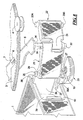
- Figure 1 shows various components of the tape extraction system in accordance with the invention. These components are contained within a housing of a tape drive, but the housing has been removed from Figure 1 for clarity. The components, as needed, are mounted to respective walls of the housing in a suitable manner, the details of which are not important to the structure or operation of the tape extraction system, and therefore the various mounting arrangements are not shown in the Figures.
- a single-reel tape cartridge 1 is loaded in the drive.
- the cartridge 1 contains a reel 39 (see Fig. 8) of magnetic recording tape, which must be extracted from the cartridge 1 and threaded onto a take-up reel 2 of the tape drive.
- the tape extraction system includes a rotatable wheel 3, having gear teeth at a periphery thereof.
- the wheel 3 is held in place by four rotatable wheel supports 4 which engage the periphery of the wheel 3.
- the wheel supports 4 are mounted to a top cover 24 (see Figure 2) of the tape drive and allow free rotation of the wheel 3.
- the wheel supports 4 are not provided with gear teeth.
- the wheel 3 has two slots 7 therein at one side thereof, which respectively engage rollers 6 of a lever arm 5. As the wheel 3 rotates (in the manner described below) the rollers 6 slide in the respective slots 7, causing the end of the lever arm 5 which projects beyond the periphery of the wheel 3 to execute an arcuate motion. The direction of the arcuate motion is dependent on the direction of rotation of the wheel 3.
- a drive motor 8 is operated to cause rotation of the wheel 3. This rotation is accomplished by a drive gear 9 connected to a drive shaft of the motor 8, which engages a gear 10.
- the gear 10 is co-rotationally fixed to a worm 11.
- the worm 11 engages a lower spur gear 12, which is co-rotationally fixed to an upper spur gear 13.
- the upper spur gear 13 engages a first intermediate gear 14, which in turn engages a second intermediate gear 15, which engages the gear teeth at the periphery of the wheel 3, thereby causing rotation of the wheel 3 in a direction dependent on the rotational direction of the drive shaft of the motor 8.
- Another motor 16 is provided as part of the extraction system, which has a drive shaft on which a worm 17 is co-rotationally mounted.
- the worm 17 engages an intermediate gear 18, which engages gear teeth on the periphery of a flange 19 of a gripper switch 20.
- the gripper switch 20 is thus caused to rotate by the operation of the motor 16, for the purpose described in more detail below.
- a gripper hook 21 engages the gripper hook switch 20. This engagement is accomplished by means of a peg 32 (see Figure 4) disposed at a bottom of the gripper hook 21, which non-permanently engages a bore 27 (see Figure 3) of the gripper switch 20. The gripper hook 21 thus proceeds between brackets 28A and 28B (see figure 3) of the gripper switch 20.
- the gripper hook 21 engages a gripper hook follower in a manner described in more detail below with an articulated engagement or hinge, allowing pivoting of the gripper hook and the gripper hook follower 22 relative to each other.
- the gripper hook follower 22 has an upper peg 23A and a lower peg 23B.
- Figure 2 also shows a tape guide 25 mounted to the top cover 24 of the tape drive.
- a fan arrangement 26 can also be seen in Figure 2, which is located on the bottom surface of the bottom flange 2B of the take-up reel 2, which also has a top flange 2A. This fan arrangement 26 is not important to the structure or operation of the extraction system.
- the gripper switch 20 is shown in Figure 3. As already noted, the gripper switch 20 has a lower flange 19 with gear teeth at a periphery thereof, with a bore 27 proceeding through the flange 19. Next to the bore 27 are upwardly projecting brackets or guides 28A and 28B.
- the gripper hook 21 is shown in Figure 4 and the gripper hook follower 22 is shown in Figure 5.
- the gripper hook 21 has a hook 29 at one end thereof, adapted to engage the tape leader pin 35, in the manner described in detail below.
- the gripper hook 21 at its other end has a bore 30, a recess 31 and a bottom peg 32.
- the gripper hook follower 22 as shown in Figure 5, has a projection 33 at one end, which fits into the recess 31 in the gripper hook 21.
- a pin or axle 34 extending downwardly from the bottom of the lever arm 5 proceeds through the bore 30 and through a bore 33A in the projection 33, thereby forming an articulated or hinged engagement between the gripper hook 21 and the gripper hook follower 22, allowing those components to pivot relative to each other around the axle 34.
- Figures 6, 7 and 8 respectively show three stages, which occur in succession, in a tape extraction procedure using the tape extraction system. This procedure will be described in more detail below.
- the cartridge 1 contains a reeled tape pack 39 of magnetic recording tape, the free end 36 thereof being accessible via an access opening 43 in the cartridge 1.
- the housing of the cartridge 1 has a recess 37 in a bottom wall thereof in recess 38 in a top wall thereof.
- the hub of the reel (not shown) for the tape pack 39 in the cartridge 1 has a suitable biasing arrangement, such as a spring, which biases the reel to urge the free end 36 of the recording tape into the housing of the cartridge 1.
- the top and bottom of the leader pin 35 proceed into, and are engaged by, the respective recess 38 and 37, so that the free end 36 is held at the access opening 43.
- the pin 35, engaged in the recesses 37 and 38, is accessible via the access opening 43.
- the tape guide 25 as shown in Figure 9 has a channel 40 therein in which the upper peg 23A of the gripper hook follower 22 is guided, as is the pin 34 of the lever arm 5, which forms the articulated hinge between the gripper hook 21 and the gripper hook follower 22.
- the tape 36 (only a portion of which is shown in Figure 9) also follows through the path of the channel 40 in the tape guide 25 as the lever arm 5 is moved in the direction of the curved arrow shown in Figure 9.
- the motor 8 is operated to rotate the wheel 3 to cause the lever arm 5 to move toward the left in Figure 6.
- the motor 16 is operated to rotate the gripper switch 20 so that it rotates slightly counterclockwise.
- the upper and lower pegs 23A and 23B are, as always, engaged in the channel 40 of the tape guide 25.
- the counterclockwise rotation of the gripper switch 20 as the lever arm 5 causes the gripper hook 21 to move into the access opening 43 without the hook 29 engaging the leader pin 35.
- the drive motor (not shown) for the take-up reel 2 in the tape drive is caused to operate to bring channels 42A and 42B respectively in the top flange 2A and the bottom flange 2B of the take-up reel 2 into alignment with the exit of the channel 40 in the tape guide 25.
- the continued movement of the lever arm 5 moves the gripper hook follower 22 and the gripper hook 21 through these channels 42A and 42B into the hub 38 of the take-up reel 2.
- the pin 34 of the lever arm 5 is stopped by engagement in a recess in a bracket 41.
- the channel proceeds through the hub 38 as indicated by the dashed lines so that the gripper hook follower 22 is located in this extension of the channel and the gripper hook 21 is located at the other side, with the leader pin 35 located at the periphery of the hub 38.
- the magnetic recording tape (which is not shown in Figure 10 for clarity) is then wound on the periphery of the hub 38 as the take-up reel 2 is rotated.
- the diameter of the axle 34 is sufficiency smaller than the diameter of the bores 30 and 33A respectively in the gripper hook 21 and the gripper hook follower 22 so that the axle 34 can remain in place without hindering rotation of the take-up reel 2.
Landscapes
- Replacement Of Web Rolls (AREA)
Applications Claiming Priority (2)
| Application Number | Priority Date | Filing Date | Title |
|---|---|---|---|
| US10/376,689 US6908055B2 (en) | 2003-02-27 | 2003-02-27 | System for extracting magnetic recording tape from a tape cartridge for engagement with a take-up reel |
| US376689 | 2003-02-27 |
Publications (3)
| Publication Number | Publication Date |
|---|---|
| EP1453046A2 true EP1453046A2 (de) | 2004-09-01 |
| EP1453046A3 EP1453046A3 (de) | 2007-05-02 |
| EP1453046B1 EP1453046B1 (de) | 2009-02-18 |
Family
ID=32771502
Family Applications (1)
| Application Number | Title | Priority Date | Filing Date |
|---|---|---|---|
| EP03015199A Expired - Lifetime EP1453046B1 (de) | 2003-02-27 | 2003-07-04 | System zum Ausziehen eines Magnetaufzeichnungsbandes aus einer Bandkassette zum Verbinden mit einer Aufwickelspule |
Country Status (3)
| Country | Link |
|---|---|
| US (1) | US6908055B2 (de) |
| EP (1) | EP1453046B1 (de) |
| DE (1) | DE60326210D1 (de) |
Cited By (1)
| Publication number | Priority date | Publication date | Assignee | Title |
|---|---|---|---|---|
| GB2420657A (en) * | 2004-11-30 | 2006-05-31 | Mitsumi Electric Co Ltd | Recording and/or Reproducing Device Having A Positioning Arrangement For Fixing A Grabber In Place |
Families Citing this family (8)
| Publication number | Priority date | Publication date | Assignee | Title |
|---|---|---|---|---|
| DK2083007T3 (da) * | 2003-11-03 | 2013-07-29 | Boehringer Ingelheim Int | Tiotropiumsalte, fremgangsmåder til deres fremstilling og lægemiddelformuleringer indeholdende disse |
| JP5165244B2 (ja) * | 2003-11-03 | 2013-03-21 | ベーリンガー インゲルハイム インターナショナル ゲゼルシャフト ミット ベシュレンクテル ハフツング | チオトロピウム塩の製法、チオトロピウム塩及びそれを含有する医薬組成物 |
| JP4593355B2 (ja) * | 2005-05-12 | 2010-12-08 | Necパーソナルプロダクツ株式会社 | 磁気テープ装置 |
| US7701662B2 (en) * | 2007-01-26 | 2010-04-20 | Quantum Corporation | Cartridge reel lock release sensing systems and methods |
| US7520461B1 (en) | 2008-01-04 | 2009-04-21 | Tandberg Storage Asa | Tape reel hub with magnetic gripper holder |
| US7500633B1 (en) | 2008-01-04 | 2009-03-10 | Tandberg Storage Asa | Tape reel hub with leader pin alignment |
| MX354929B (es) | 2011-10-13 | 2018-03-16 | Tenfold Tech Llc | Sistema y método balanceados para la elaboración de productos microbianos. |
| JP5942953B2 (ja) * | 2013-09-25 | 2016-06-29 | 日本電気株式会社 | 線条材搬送機構、線条材搬送方法、及びテープ搬送機構 |
Citations (1)
| Publication number | Priority date | Publication date | Assignee | Title |
|---|---|---|---|---|
| EP1054396A2 (de) | 1999-05-18 | 2000-11-22 | Nec Corporation | Mechanismus für Bandgerät |
Family Cites Families (17)
| Publication number | Priority date | Publication date | Assignee | Title |
|---|---|---|---|---|
| US1796417A (en) * | 1927-08-29 | 1931-03-17 | Wittek Joseph | Automatic feed for punch presses |
| US2748865A (en) * | 1951-02-27 | 1956-06-05 | George H Kuhl | Punch press and feed mechanism therefor |
| NL6915961A (de) * | 1968-11-27 | 1970-05-29 | ||
| US3647127A (en) * | 1970-04-30 | 1972-03-07 | Littell Machine Co F J | Feeding apparatus for strip material |
| US3753522A (en) * | 1971-02-19 | 1973-08-21 | Red Bud Ind Inc | Sheet transferring device and method |
| US4399936A (en) * | 1981-10-26 | 1983-08-23 | International Business Machines Corp. | Pantocam web threading apparatus |
| US4826101A (en) * | 1986-03-21 | 1989-05-02 | Smith Jay A | Apparatus for loading and unloading the leader block of a tape cartridge |
| DD251330B5 (de) * | 1986-07-25 | 1993-11-04 | Zirkon Druckmaschinen Gmbh | Korrekturwalze, insbesondere fuer einen rotationsfalzapparat |
| DE3919291C2 (de) * | 1988-06-14 | 1995-07-06 | Tokyo Kikai Seisakusho Ltd | Bahnvorschubrolle und Antriebssteueranordnung hierfür |
| US5155639A (en) * | 1988-11-03 | 1992-10-13 | U.S. Philips Corporation | Transport apparatus for a single reel tape cartridge |
| US5239904A (en) * | 1990-08-08 | 1993-08-31 | Max Co., Ltd. | Punch |
| US5720421A (en) * | 1994-02-28 | 1998-02-24 | Vamco Machine & Tool, Inc. | Elecronically controlled high speed press feed |
| US5913470A (en) * | 1997-01-13 | 1999-06-22 | Scribner; Albert Willis | Roll feeder |
| US6079651A (en) * | 1997-10-23 | 2000-06-27 | Seagate Technology, Inc. | Tape coupling arrangement for single reel cartridge |
| US6034839A (en) * | 1997-11-07 | 2000-03-07 | Seagate Technology, Inc. | Mechanism and method for loading a tape from a cartridge to a take-up reel |
| US6378796B1 (en) * | 1999-10-08 | 2002-04-30 | Seagate Technology Llc | Apparatus and method for de-coupling grabber from take-up reel |
| JP3390385B2 (ja) * | 1999-11-05 | 2003-03-24 | 米沢日本電気株式会社 | 磁気記録/再生装置におけるスレッディング機構 |
-
2003
- 2003-02-27 US US10/376,689 patent/US6908055B2/en not_active Expired - Fee Related
- 2003-07-04 EP EP03015199A patent/EP1453046B1/de not_active Expired - Lifetime
- 2003-07-04 DE DE60326210T patent/DE60326210D1/de not_active Expired - Lifetime
Patent Citations (1)
| Publication number | Priority date | Publication date | Assignee | Title |
|---|---|---|---|---|
| EP1054396A2 (de) | 1999-05-18 | 2000-11-22 | Nec Corporation | Mechanismus für Bandgerät |
Cited By (2)
| Publication number | Priority date | Publication date | Assignee | Title |
|---|---|---|---|---|
| GB2420657A (en) * | 2004-11-30 | 2006-05-31 | Mitsumi Electric Co Ltd | Recording and/or Reproducing Device Having A Positioning Arrangement For Fixing A Grabber In Place |
| US7420767B2 (en) | 2004-11-30 | 2008-09-02 | Mitsumi Electric Co., Ltd. | Recording and/or reproducing device having a positioning arrangement for fixing a grabber in place |
Also Published As
| Publication number | Publication date |
|---|---|
| DE60326210D1 (de) | 2009-04-02 |
| EP1453046B1 (de) | 2009-02-18 |
| US20040169101A1 (en) | 2004-09-02 |
| US6908055B2 (en) | 2005-06-21 |
| EP1453046A3 (de) | 2007-05-02 |
Similar Documents
| Publication | Publication Date | Title |
|---|---|---|
| US4796115A (en) | Tape loading device for a cassette type tape recording and/or reproducing apparatus | |
| JPS5913097B2 (ja) | 自動ウエブ通し装置 | |
| US6908055B2 (en) | System for extracting magnetic recording tape from a tape cartridge for engagement with a take-up reel | |
| JPS5913095B2 (ja) | 自動ウエブ通し装置 | |
| EP1048027B1 (de) | Aufzeichnungs-und/oder wiedergabeeinrichtung mit einer aufwickelspule und mit einer an der aufwickelspule tangential positionierbaren bandauszieheinheit | |
| KR850001906B1 (ko) | 비데오테이프 레코오더 | |
| US6267313B1 (en) | Wide tape cartridge | |
| EP1048029B1 (de) | Aufzeichnungs-und/oder wiedergabeeinrichtung mit einem bandausziehelement, einem kopplungselement und einer führungsvorrichtung für diese elemente | |
| EP1048030B1 (de) | Aufzeichnungs-und/oder wiedergabeeinrichtung mit einer aufwickelspule und mit einer an der aufwickelspule radial positionierbaren bandauszieheinheit | |
| EP0585361A1 (de) | Magnetbandkassette für transportvorrichtung mit schraubenförmiger abtastung. | |
| EP1048031A1 (de) | Aufzeichnungs-und/oder wiedergabeeinrichtung mit antriebsmitteln zum verstellen von aufnahmemitteln für eine kassette und von haltemitteln für einen bandausziehteil | |
| JP2006155683A (ja) | 記録再生装置 | |
| US6441990B2 (en) | Compact tape drive having delayed in time first, second and third rotated tape guides for reading and writing data on single reel magnetic tape cartridges | |
| US6876512B2 (en) | Tape cartridge docking apparatus for read/write recording assemblies and method therefor | |
| JP2976556B2 (ja) | テープカセット | |
| US6522500B1 (en) | Tape cartridge for extremely wide tape having an access opening allowing extraction of tape, and tape drive for use therewith | |
| JP4060852B2 (ja) | データ記憶システム用のギャップ充填ブロック付き巻き取りハブを有するテープ装填装置及び方法 | |
| JP2986318B2 (ja) | 磁気記録再生装置 | |
| US6590743B2 (en) | Head protection mechanism for use in a tape drive that is driven by a ring cam | |
| JP2893987B2 (ja) | テーププレーヤ | |
| JP2007226895A (ja) | 記録再生装置及びそれに使用される巻取りリール | |
| EP1363289A1 (de) | Bandkassette und Laufwerk für sehr breite Band | |
| JPH08235708A (ja) | ライブラリ装置 | |
| JPH03272049A (ja) | 情報記録再生装置 | |
| JPS6089863A (ja) | 磁気記録再生装置 |
Legal Events
| Date | Code | Title | Description |
|---|---|---|---|
| PUAI | Public reference made under article 153(3) epc to a published international application that has entered the european phase |
Free format text: ORIGINAL CODE: 0009012 |
|
| AK | Designated contracting states |
Kind code of ref document: A2 Designated state(s): AT BE BG CH CY CZ DE DK EE ES FI FR GB GR HU IE IT LI LU MC NL PT RO SE SI SK TR |
|
| AX | Request for extension of the european patent |
Extension state: AL LT LV MK |
|
| PUAL | Search report despatched |
Free format text: ORIGINAL CODE: 0009013 |
|
| AK | Designated contracting states |
Kind code of ref document: A3 Designated state(s): AT BE BG CH CY CZ DE DK EE ES FI FR GB GR HU IE IT LI LU MC NL PT RO SE SI SK TR |
|
| AX | Request for extension of the european patent |
Extension state: AL LT LV MK |
|
| 17P | Request for examination filed |
Effective date: 20070612 |
|
| 17Q | First examination report despatched |
Effective date: 20070814 |
|
| AKX | Designation fees paid |
Designated state(s): DE GB |
|
| GRAP | Despatch of communication of intention to grant a patent |
Free format text: ORIGINAL CODE: EPIDOSNIGR1 |
|
| GRAS | Grant fee paid |
Free format text: ORIGINAL CODE: EPIDOSNIGR3 |
|
| GRAA | (expected) grant |
Free format text: ORIGINAL CODE: 0009210 |
|
| AK | Designated contracting states |
Kind code of ref document: B1 Designated state(s): DE GB |
|
| REG | Reference to a national code |
Ref country code: GB Ref legal event code: FG4D |
|
| REF | Corresponds to: |
Ref document number: 60326210 Country of ref document: DE Date of ref document: 20090402 Kind code of ref document: P |
|
| PLBE | No opposition filed within time limit |
Free format text: ORIGINAL CODE: 0009261 |
|
| STAA | Information on the status of an ep patent application or granted ep patent |
Free format text: STATUS: NO OPPOSITION FILED WITHIN TIME LIMIT |
|
| 26N | No opposition filed |
Effective date: 20091119 |
|
| PGFP | Annual fee paid to national office [announced via postgrant information from national office to epo] |
Ref country code: GB Payment date: 20220707 Year of fee payment: 20 Ref country code: DE Payment date: 20220831 Year of fee payment: 20 |
|
| REG | Reference to a national code |
Ref country code: DE Ref legal event code: R071 Ref document number: 60326210 Country of ref document: DE |
|
| REG | Reference to a national code |
Ref country code: GB Ref legal event code: PE20 Expiry date: 20230703 |
|
| PG25 | Lapsed in a contracting state [announced via postgrant information from national office to epo] |
Ref country code: GB Free format text: LAPSE BECAUSE OF EXPIRATION OF PROTECTION Effective date: 20230703 |